

Heatilator CRAVE7260-B, CRAVE4836ST-B, CRAVE6048-B, CRAVE8472ST-B, CRAVE6048ST-B Installation And Appliance Setup
...
1
Heatilator • CRAVE4836/ST-B, CRAVE6048/ST-B, CRAVE7260/ST-B, CRAVE8472/ST-B Installation Manual • 2301-973 Rev. H • 5/17
Models:
Installation Manual
Installation and Appliance Setup
INSTALLER: Leave this manual with party responsible for use and operation.
OWNER: Retain this manual for future reference.
NOTICE: DO NOT discard this manual!
In the Commonwealth of Massachusetts installation must be
performed by a licensed plumber or gas tter.
See Table of Contents for location of additional Commonwealth
of Massachusetts requirements.
This appliance may be installed as an OEM
installation in manufactured home (USA
only) or mobile home and must be installed
in accordance with the manufacturer’s
instructions and the Manufactured Home
Construction and Safety Standard, Title 24
CFR, Part 3280 in the United States, or the
Standard for Installation in Mobile Homes,
CAN/CSA Z240 MH Series, in Canada.
This appliance is only for use with the type(s)
of gas indicated on the rating plate. This
appliance is not convertible for use with other
gases, unless a certied kit is used.
• DO NOT store or use gasoline or other am-
mable vapors and liquids in the vicinity of this
or any other appliance.
• What to do if you smell gas
- DO NOT try to light any appliance.
- DO NOT touch any electrical switch. DO
NOT use any phone in your building.
- Leave the building immediately.
- Immediately call your gas supplier from
a neighbor’s phone. Follow the gas supplier’s instructions.
- If you cannot reach your gas supplier, call
the re department.
• Installation and service must be performed
by a qualied installer, service agency, or the
gas supplier.
WARNING:
FIRE OR EXPLOSION HAZARD
Failure to follow safety warnings exactly
could result in serious injury, death, or
property damage.
DANGER
HOT GLASS WILL
CAUSE BURNS.
DO NOT TOUCH GLASS
UNTIL COOLED.
NEVER ALLOW CHILDREN
TO TOUCH GLASS.
A barrier designed to reduce the risk of
burns from the hot viewing glass is provided
with this appliance and shall be installed for
the protection of children and other at-risk
individuals.
CRAVE4836-B
CRAVE4836ST-B
CRAVE6048-B
CRAVE6048ST-B
CRAVE7260-B
CRAVE7260ST-B
CRAVE8472-B
CRAVE8472ST-B

2
Heatilator • CRAVE4836/ST-B, CRAVE6048/ST-B, CRAVE7260/ST-B, CRAVE8472/ST-B Installation Manual • 2301-973 Rev. H • 5/17
Safety Alert Key:
• DANGER! Indicates a hazardous situation which, if not avoided will result in death or serious injury.
• WARNING! Indicates a hazardous situation which, if not avoided could result in death or serious injury.
• CAUTION! Indicates a hazardous situation which, if not avoided, could result in minor or moderate injury.
• NOTICE: Used to address practices not related to personal injury.
Table of Contents
Installation Standard Work Checklist ....................3
1 Product Specic and Important Safety Information
A. Appliance Certication ............................4
B. Glass Specications ..............................4
C. BTU Specications ............................... 4
D. High Altitude Installations .......................... 5
E. Non-Combustible Materials Specication. . . . . . . . . . . . . . 5
F. Combustible Materials Specication .................5
G. Electrical Codes .................................5
H. Requirements for the Commonwealth of Massachusetts . . 6
2 Getting Started
A. Design and Installation Considerations ............... 7
B. Good Faith Wall Surface/TV Guidelines ..............7
C. Tools and Supplies Needed ........................8
D. Inspect Appliance and Components .................. 8
3 Framing and Clearances
A. Appliance/Decorative Front Dimension Diagrams .......9
B. Clearances to Combustibles ......................16
C. Constructing the Appliance Chase .................. 20
D. Floor Protection ................................20
4 Termination Location and Vent Information
A. Vent Termination Minimum Clearances .............. 21
B. Chimney Diagram. . . . . . . . . . . . . . . . . . . . . . . . . . . . . . . 22
C. Approved Pipe .................................23
D. Use of Elbows .................................23
E. Measuring Standards ............................ 23
F. Vent Diagrams .................................23
5 Vent Clearances and Framing
A. Pipe Clearances to Combustibles .................. 31
B. Wall Penetration Framing/Firestops .................31
C. Install the Ceiling Firestop ........................32
D. Install Attic Insulation Shield ....................... 32
E. Installing the Optional Heat-Zone
®
Gas Kit ...........33
6 Appliance Preparation
A. Top Standoff Preparation .........................34
B. Vent Collar Preparation ..........................34
C. Securing and Leveling the Appliance ................ 35
D. Installing Non-Combustible Facing Material .......... 36
7 Venting and Chimneys
A. Assemble Vent Sections .........................37
B. Assemble Slip Sections ..........................38
C. Secure The Vent Sections ........................38
D. Disassemble Vent Sections .......................39
E. Vertical Termination Requirements ..................40
F. Horizontal Termination Requirements ...............41
8 Electrical Information
A. General Information .............................43
B. Wiring Requirements ............................44
9 Gas Information
A. Fuel Conversion ................................ 45
B. Gas Pressure ..................................45
C. Gas Service Access .............................45
D. Gas Connection ................................47
E. High Altitude Installations .........................47
F. Air Shutter Setting ..............................48
10 Finishing
A. Facing and Finishing Instructions. . . . . . . . . . . . . . . . . . . 49
B. Decorative Fronts ...............................53
C. Mantel and Wall Projections .......................58
11 Appliance Setup
A. Fixed Glass Assembly ........................... 60
B. Remove the Shipping Materials/Install Bottom Glass
Shield ........................................60
C. Clean the Appliance .............................60
D. Install Glass Refractory (Optional) .................. 60
E. Install Media .................................. 60
F. Install Log Set (Optional) .........................60
12 Reference Materials
A. Vent Components Diagrams ......................61
B. Accessories ................................... 67
= Contains updated information.
3
Heatilator • CRAVE4836/ST-B, CRAVE6048/ST-B, CRAVE7260/ST-B, CRAVE8472/ST-B Installation Manual • 2301-973 Rev. H • 5/17
Installation Standard Work Checklist
Customer:
Lot/Address:
Model
(circle one): CRAVE4836-B CRAVE6048-B CRAVE 7260-B
CRAVE8472-B CRAVE4836ST-B CRAVE6048ST-B CRAVE 7260ST-B
CRAVE8472ST-B
Date Installed:
Location of Fireplace:
Installer:
Dealer/Distributor Phone #
Serial #:
Comments: Further description of the issues, who is responsible (Installer/ Builder/ Other Trades, etc) and corrective
action needed _____________________________________________________________________________________
_________________________________________________________________________________________________
Comments Communicated to party responsible ____________________ by ______________________on ___________
(Builder / Gen. Contractor/) (Installer) (Date)
Appliance Install Sections 3 and 6 YES IF NO, WHY?
Veri ed that the chase is insulated and sealed. (Pg. 20) ___________________________
Required factory included non-combustible board is in place. (Pg. 36) ___________________________
Veri ed clearances to combustibles. (Pg. 16-19) ___________________________
Fireplace is leveled and secured. (Pg. 35) ___________________________
Pipe heat shield is attached to header. Header no wider than 3.5 in.(2x4)
(Pg. 18, 19, 34) ___________________________
Venting/Chimney Sections 4,5 and 7
Venting con guration complies to vent diagrams. (Pg 23-30) ___________________________
Venting installed, locked, and secured in place with proper clearance. ___________________________
Firestops installed. (Section 5) ___________________________
Attic insulation shield installed. (Pg 32) ___________________________
Exterior wall/Roof ashing installed and sealed. (Section 7) ___________________________
Terminations installed and sealed. (Section 7) ___________________________
Electrical Section 8 (Pg 43-44)
Unswitched power (110-120 VAC) provided to the appliance. ___________________________
Switch wires properly installed. ___________________________
Gas Section 9 (Pg 45-48)
Proper appliance for fuel type. ___________________________
Was a conversion performed? ___________________________
Leak check performed and inlet pressure veri ed. ___________________________
Veri ed proper air shutter setting for installation type. ___________________________
Finishing Section 10 (Pg 49-58)
Combustible materials not installed in non-combustible areas. ___________________________
Veri ed all clearances meet installation manual requirements. ___________________________
Finishing done correctly using inside t or overlap t method. ___________________________
Finishing template removed. ___________________________
Mantels and wall projections comply with installation manual requirements. ___________________________
Appliance Setup Section 11 (Pg 59-62)
All packaging and protective materials removed (inside & outside of appliance). ___________________________
Refractories and media installed correctly. ___________________________
Glass assembly installed and secured. ___________________________
Accessories installed properly. ___________________________
Decorative front properly installed. ___________________________
Manual bag and all of its contents are removed from inside/under
the appliance and given to party responsible for use and operation. ___________________________
Started appliance and veri ed no gas leaks exist. ___________________________
Lights work in all switched positions (if so equipped). ___________________________
Component heat shield is installed. (Pg. 43.) ___________________________
2301-975 Rev. B 4/17
= Contains updated information.
Hearth & Home Technologies recommends the following:
• Photographing the installation and copying this checklist for your le.
• That this checklist remain visible at all times on the appliance until the installation is complete.
This standard work checklist is to be used by the installer in conjunction with, not instead of, the instructions contained in this
installation manual.
WARNING! Risk of Fire or Explosion! Failure to install appliance according to these instructions can
lead to a re or explosion.
ATTENTION INSTALLER:
Follow this Standard Work Checklist
4
Heatilator • CRAVE4836/ST-B, CRAVE6048/ST-B, CRAVE7260/ST-B, CRAVE8472/ST-B Installation Manual • 2301-973 Rev. H • 5/17
B. Glass Specications
This appliance is equipped with 5 mm ceramic glass. Replace glass only with 5 mm ceramic glass. Please contact
your dealer for replacement glass.
This product is listed to ANSI standards for “Vented Gas
Fireplace Heaters” and applicable sections of “Gas Burn-
ing Heating Appliances for Manufactured Homes and
Recreational Vehicles”, and “Gas Fired Appliances for
Use at High Altitudes”.
A. Appliance Certication
NOT INTENDED FOR USE AS A PRIMARY HEAT SOURCE.
This appliance is tested and approved as either supplemen-
tal room heat or as a decorative appliance. It should not be
factored as primary heat in residential heating calculations.
NOTICE: This installation must conform with local codes.
In the absence of local codes you must comply with the
National Fuel Gas Code, ANSI Z223.1-latest edition in
the U.S.A. and the CAN/CGA B149 Installation Codes in
Canada.
1
Product Specic and Important Safety Information
C. BTU Specications
MODEL: CRAVE4836-B, CRAVE4836ST-B
CRAVE6048-B, CRAVE6048ST-B,
CRAVE7260-B, CRAVE7260ST-B
CRAVE8472-B. CRAVE8472ST-B
LABORATORY: Underwriters Laboratories, Inc. (UL)
TYPE: Direct Vent Heater
STANDARD: ANSI Z21.88-2014/CSA 2.33-2014
Models
(U.S. or Canada)
Maximum
Input BTU/h
Minimum
Input
BTU/h
Orice
Size
(DMS)
CRAVE4836-B
(NG)
(0-2000 FT) 30,000 17,500 #36
CRAVE4836-B
(Propane)
(0-2000 FT) 29,000 15,500 #52
CRAVE4836ST-B
(NG)
(0-2000 FT) 30,000 17,500 #36
CRAVE4836ST-B
(Propane)
(0-2000 FT) 29,000 15,500 #52
CRAVE6048-B
(NG)
(0-2000 FT) 40,000 21,000 .124
CRAVE6048-B
(Propane)
(0-2000 FT) 36,000 19,500 #49
CRAVE6048ST-B
(NG)
(0-2000 FT) 40,000 21,000 .124
CRAVE6048ST-B
(Propane)
(0-2000 FT) 36,000 19,500 #49
CRAVE7260-B
(NG)
(0-2000 FT) 50,000 26,000 #28
CRAVE7260-B
(Propane)
(0-2000 FT) 41,000 22,000 #48
CRAVE7260ST-B
(NG)
(0-2000 FT) 50,000 26,000 #28
CRAVE7260ST-B
(Propane)
(0-2000 FT) 41,000 22,000 #48
CRAVE8472-B
(NG)
(0-2000 FT) 58,000 30,000 #23
CRAVE8472-B
(Propane)
(0-2000 FT) 46,000 24,000 #45
CRAVE8472ST-B
(NG)
(0-2000 FT) 58,000 30,000 #23
CRAVE8472ST-B
(Propane)
(0-2000 FT) 46,000 24,000 #45

5
Heatilator • CRAVE4836/ST-B, CRAVE6048/ST-B, CRAVE7260/ST-B, CRAVE8472/ST-B Installation Manual • 2301-973 Rev. H • 5/17
E. Non-Combustible Materials Specication
Material which will not ignite and burn. Such materials are
those consisting entirely of steel, iron, brick, tile, concrete,
slate, glass or plasters, or any combination thereof.
Materials that are reported as passing ASTM E 136,
Standard Test Method for Behavior of Materials in
a Vertical Tube Furnace at 750 ºC shall be considered
non-combustible materials.
F. Combustible Materials Specication
Materials made of or surfaced with wood, compressed pa-
per, plant bers, plastics, or other material that can ignite
and burn, whether ame proofed or not, or plastered or
unplastered shall be considered combustible materials.
G. Electrical Codes
NOTICE: This appliance must be electrically wired
and grounded in accordance with local codes or, in the
absence of local codes, with National Electric Code
ANSI/NFPA 70-latest edition or the Canadian Electric
Code CSA C22.1.
• A 110-120 VAC circuit for this product must be pro-
tected with ground-fault circuit-interrupter protection,
in compliance with the applicable electrical codes,
when it is installed in locations such as in bathrooms
or near sinks.
D. High Altitude Installations
NOTICE: If the heating value of the gas has been reduced,
these rules do not apply. Check with your local gas utility
or authorities having jurisdiction.
When installing above 2000 feet elevation:
• In the USA: Reduce input rate 4% for each 1000 feet
above 2000 feet.
• In CANADA: Input ratings are certied without a
reduction of input rate for elevations up to 4500 feet
(1370 m)above sea level. Please consult provincial and/
or local authorities having jurisdiction for installations at
elevations above 4500 feet (1370 m).
Check with your local gas utility to determine proper
orice size.

6
Heatilator • CRAVE4836/ST-B, CRAVE6048/ST-B, CRAVE7260/ST-B, CRAVE8472/ST-B Installation Manual • 2301-973 Rev. H • 5/17
H. Requirements for the Commonwealth of
Massachusetts
For all side wall horizontally vented gas fueled equipment
installed in every dwelling, building or structure used in
whole or in part for residential purposes, including those
owned or operated by the Commonwealth and where the
side wall exhaust vent termination is less than seven (7)
feet above nished grade in the area of the venting, including but not limited to decks and porches, the following
requirements shall be satised:
Installation of Carbon Monoxide Detectors
At the time of installation of the side wall horizontal vented
gas fueled equipment, the installing plumber or gas tter
shall observe that a hard wired carbon monoxide detector
with an alarm and battery back-up is installed on the oor
level where the gas equipment is to be installed. In addition, the installing plumber or gas tter shall observe that
a battery operated or hard wired carbon monoxide detec-
tor with an alarm is installed on each additional level of
the dwelling, building or structure served by the side wall
horizontal vented gas fueled equipment. It shall be the
responsibility of the property owner to secure the services
of qualied licensed professionals for the installation of
hard wired carbon monoxide detectors.
In the event that the side wall horizontally vented gas fu-
eled equipment is installed in a crawl space or an attic,
the hard wired carbon monoxide detector with alarm and
battery back-up may be installed on the next adjacent
oor level.
In the event that the requirements of this subdivision can
not be met at the time of completion of installation, the
owner shall have a period of thirty (30) days to comply
with the above requirements; provided, however, that during said thirty (30) day period, a battery operated carbon
monoxide detector with an alarm shall be installed.
Approved Carbon Monoxide Detectors
Each carbon monoxide detector as required in accordance with the above provisions shall comply with NFPA
720 and be ANSI/UL 2034 listed and IAS certied.
Signage
A metal or plastic identication plate shall be permanently mounted to the exterior of the building at a minimum
height of eight (8) feet above grade directly in line with the
exhaust vent terminal for the horizontally vented gas fueled heating appliance or equipment. The sign shall read,
in print size no less than one-half (1/2) in. in size, “GAS
VENT DIRECTLY BELOW. KEEP CLEAR OF ALL OBSTRUCTIONS”.
Inspection
The state or local gas inspector of the side wall horizontally vented gas fueled equipment shall not approve the
installation unless, upon inspection, the inspector ob-
serves carbon monoxide detectors and signage installed
in accordance with the provisions of 248 CMR 5.08(2)(a)1
through 4.
Exemptions
The following equipment is exempt from 248 CMR 5.08(2)
(a)1 through 4:
• The equipment listed in Chapter 10 entitled “Equipment
Not Required To Be Vented” in the most current edition
of NFPA 54 as adopted by the Board; and
• Product Approved side wall horizontally vented gas fu-
eled equipment installed in a room or structure separate
from the dwelling, building or structure used in whole or
in part for residential purposes.
MANUFACTURER REQUIREMENTS
Gas Equipment Venting System Provided
When the manufacturer of Product Approved side wall
horizontally vented gas equipment provides a venting
system design or venting system components with the
equipment, the instructions provided by the manufacturer
for installation of the equipment and the venting system
shall include:
• Detailed instructions for the installation of the venting
system design or the venting system components; and
• A complete parts list for the venting system design or
venting system.
Gas Equipment Venting System NOT Provided
When the manufacturer of a Product Approved side wall
horizontally vented gas fueled equipment does not provide the parts for venting the ue gases, but identies
“special venting systems”, the following requirements
shall be satised by the manufacturer:
• The referenced “special venting system” instructions
shall be included with the appliance or equipment installation instructions; and
• The “special venting systems” shall be Product Approved by the Board, and the instructions for that system shall include a parts list and detailed installation
instructions.
A copy of all installation instructions for all Product Approved side wall horizontally vented gas fueled equip-
ment, all venting instructions, all parts lists for venting
instructions, and/or all venting design instructions shall
remain with the appliance or equipment at the completion
of the installation.
See Gas Connection section for additional Commonwealth of Massachusetts requirements.
Note: The following requirements reference various
Massachusetts and national codes not contained in this
document.
7
Heatilator • CRAVE4836/ST-B, CRAVE6048/ST-B, CRAVE7260/ST-B, CRAVE8472/ST-B Installation Manual • 2301-973 Rev. H • 5/17
2
Getting Started
A. Design and Installation Considerations
Heat & Glo direct vent gas appliances are designed to
operate with all combustion air siphoned from outside of
the building and all exhaust gases expelled to the outside.
No additional outside air source is required.
Installation MUST comply with local, regional, state and
national codes and regulations. Consult insurance carrier,
local building inspector, re ofcials or authorities having
jurisdiction over restrictions, installation inspection and
permits.
Before installing, determine the following:
• Where the appliance is to be installed.
• The vent system conguration to be used.
• Gas supply piping.
• Electrical wiring requirements.
• Framing and nishing details.
• Whether optional accessories—devices such as a wall
switch or remote control—are desired.
Improper installation, adjustment, alteration, service or
maintenance can cause injury or property damage. For
assistance or additional information, consult a qualied
service technician, service agency or your dealer.
B. Good Faith Wall Surface/TV Guidelines
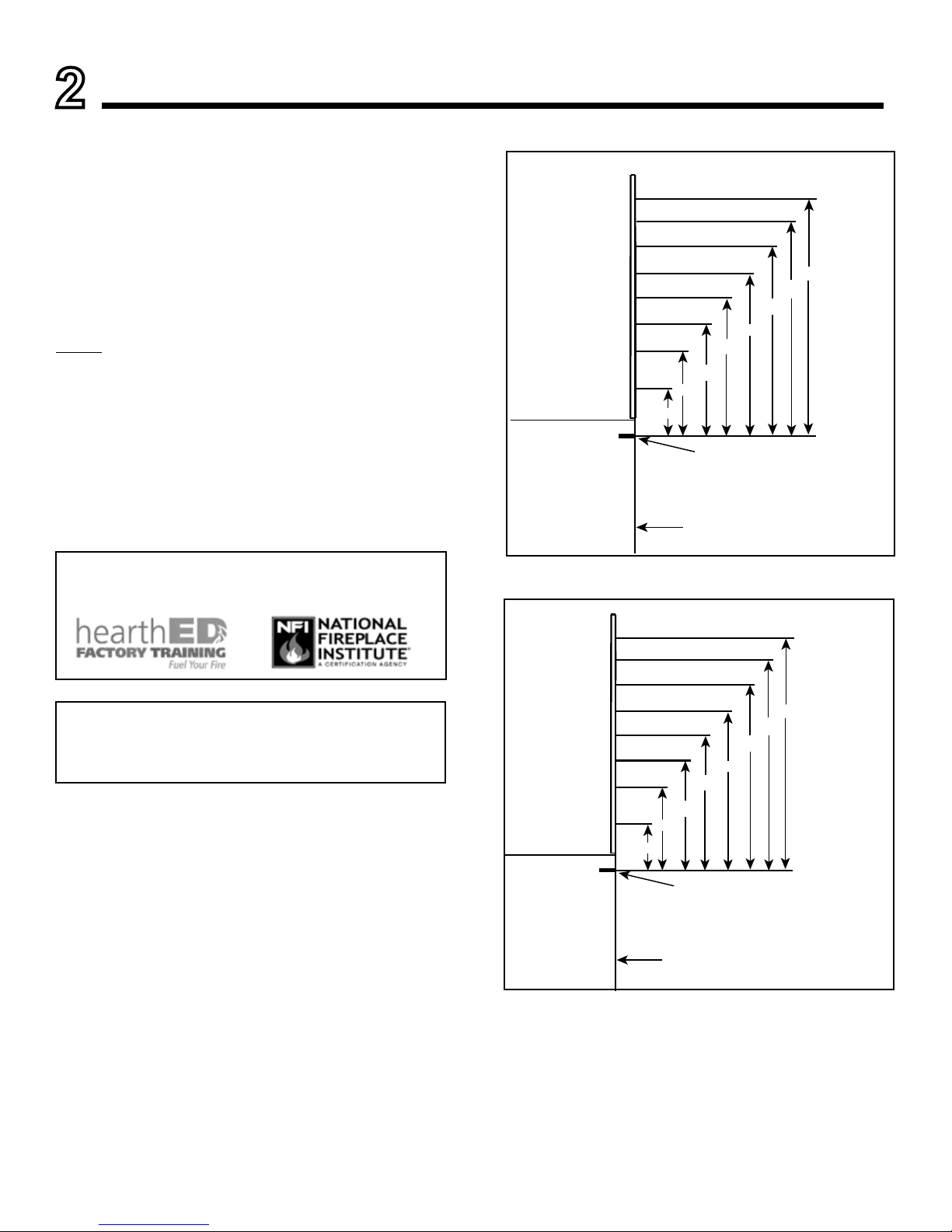
NOTICE: Temperatures listed above are taken with a
temperature measuring probe as prescribed by the test
standard used for appliance certication. Temperatures
on walls or mantels taken with an infrared thermometer
may yield increased temperatures of up to 30 degrees or
more depending on the thermometer settings and material
characteristics being measured.
Figure 2.2. Wall Surface Temperatures Above Appliance
(CRAVE7260-B/CRAVE7260ST-B/CRAVE8472-B/CRAVE8472ST-B)
MEASUREM ENTS FROM
TOP EDGE OF THE OPE NING
6 in.
18 in.
24 in.
30 in.
36 in.
48 in.
TO CEILIN G
42 in.
12 in.
245°F
APPLIANCE FRONT
190°F
155°F
140°F
135°F
125°F
125°F
Figure 2.1. Wall Surface Temperatures Above Appliance
(CRAVE4836-B/CRAVE4836ST-B/CRAVE6048-B/CRAVE6048ST-B)
MEASUREM ENTS FROM
TOP EDGE OF THE OPENING
6 in.
18 in.
24 in.
30 in.
36 in.
48 in.
TO CEILI NG
42 in.
12 in.
170°F
APPLIANCE FRONT
155°F
145°F
140°F
130°F
125°F
125°F
Installation and service of this appliance should be performed by
qualied personnel. Hearth & Home Technologies recommends
HHT Factory Trained or NFI certied professionals.
8
Heatilator • CRAVE4836/ST-B, CRAVE6048/ST-B, CRAVE7260/ST-B, CRAVE8472/ST-B Installation Manual • 2301-973 Rev. H • 5/17
D. Inspect Appliance and Components
• Carefully remove the appliance and components from
the packaging.
• The vent system components and decorative doors and
fronts may be shipped in separate packages.
• If packaged separately, the media, refractory, and/or
optional log kits must be installed.
• Report to your dealer any parts damaged in shipment,
particularly the condition of the glass.
• Read all of the instructions before starting the installation. Follow these instructions carefully during the
installation to ensure maximum safety and benet.
WARNING! Risk of Fire or Explosion! Damaged parts
could impair safe operation. DO NOT install damaged, incomplete or substitute components. Keep appliance dry.
C. Tools and Supplies Needed
Before beginning the installation be sure that the following
tools and building supplies are available.
Tape measure Framing material
Pliers Non-corrosive leak check solution
Hammer Phillips screwdriver
Gloves Framing square
Voltmeter Electric drill and bits (1/4 in. magnetic)
Plumb line Safety glasses
Level Reciprocating saw
Manometer Flat blade screwdriver
1/2 - 3/4 in. length, #6 or #8 Self-drilling screws
Caulking material (300 ºF minimum continuous exposure
rating)
Hearth & Home Technologies disclaims any responsibility
for, and the warranty will be voided by, the following actions:
• Installation and use of any damaged appliance or vent
system component.
• Modication of the appliance or vent system.
• Installation other than as instructed by Hearth & Home
Technologies.
• Improper positioning of the gas logs or the glass door.
• Installation and/or use of any component part not approved
by Hearth & Home Technologies.
Any such action may cause a re hazard.
WARNING! Risk of Fire, Explosion or Electric Shock!
DO NOT use this appliance if any part has been under
water. Call a qualied service technician to inspect the
appliance and to replace any part of the control system
and/or gas control which has been under water.
9
Heatilator • CRAVE4836/ST-B, CRAVE6048/ST-B, CRAVE7260/ST-B, CRAVE8472/ST-B Installation Manual • 2301-973 Rev. H • 5/17
3
Framing and Clearances
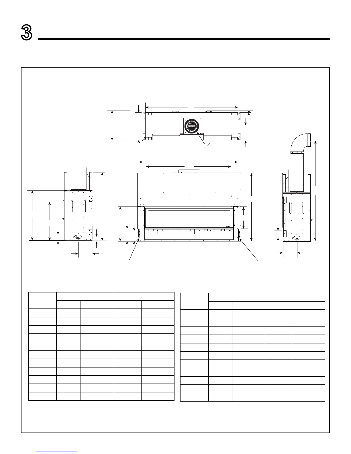
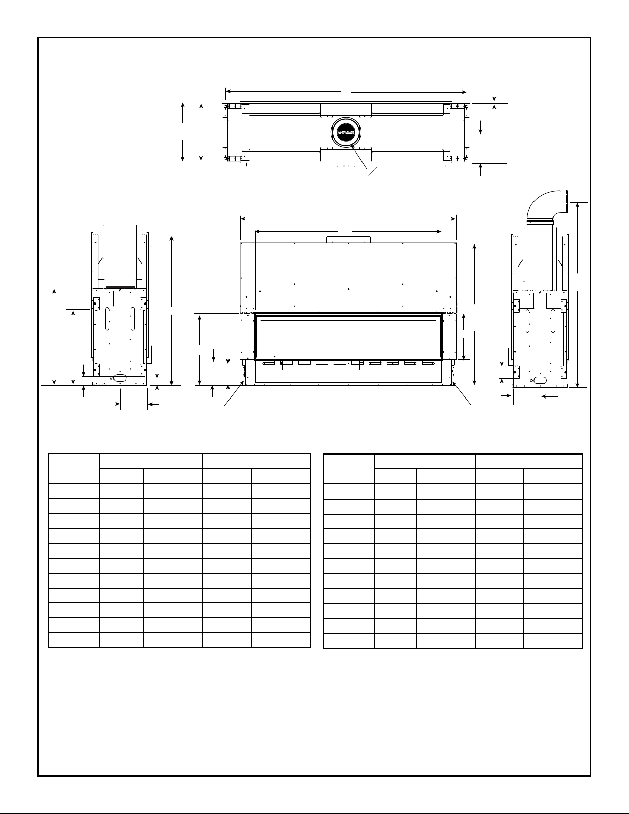
Figure 3.1 Appliance Dimensions - CRAVE4836-B,CRAVE6048-B
A. Appliance/Decorative Front Dimension Diagrams
Dimensions are actual appliance dimensions. Use for reference only. For framing dimensions and clearances refer to Section 5.
E
F
G
H
I
J
K
M
o
N
O
P
T
U
CENTERED ON APPLIANCE
L
V
B
A
C
D
Q
S
R
GAS ACCESS
ELECTRICAL ACCESS
Location
CRAVE4836-B CRAVE6048-B
Inches Millimeters Inches Millimeters
A 50 1270 62 1575
B 39-1/4 997 51-1/8 1299
C 15-5/8 397 15-5/8 397
D 42-1/2 1080 42-1/2 1080
E 4 102 4 102
F 8-9/16 217 8-9/16 217
G 63 1600 63 1600
H 8-9/16 217 8-9/16 217
I 1 25 1 25
J 46-3/16 1173 58 1473
K 17-1/8 435 17-1/8 435
Location
CRAVE4836-B CRAVE6048-B
Inches Millimeters Inches Millimeters
L 8 203 8 203
M 18-5/8 473 18-5/8 473
N 41-3/4 1060 41-3/4 1060
O 2-3/8 60 2-3/8 60
P 8-9/16 217 8-9/16 217
Q 24-1/2 622 24-1/2 622
R 7-1/4 184 7-1/4 184
S 8-7/8 225 8-7/8 225
T 2-3/4 70 2-3/4 70
U 23-3/4 603 23-3/4 603
V 30-1/2 775 30-1/2 775
10
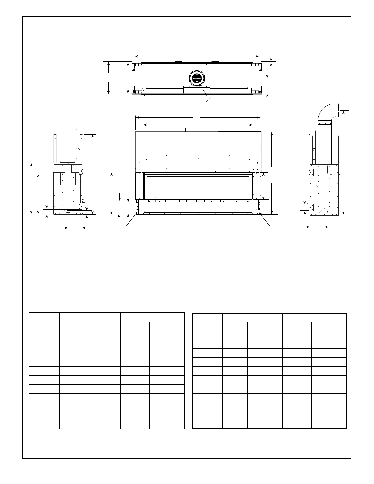
Heatilator • CRAVE4836/ST-B, CRAVE6048/ST-B, CRAVE7260/ST-B, CRAVE8472/ST-B Installation Manual • 2301-973 Rev. H • 5/17
Location
CRAVE7260-B CRAVE8472-B
Inches Millimeters Inches Millimeters
A 74 1880 86 2184
B 63-1/8 1603 75-1/8 1908
C 15-5/8 397 15-5/8 397
D 48-1/2 1232 48-1/2 1232
E 4 102 4 102
F 8-9/16 217 8-9/16 217
G 63 1600 75 1905
H 8-9/16 217 8-9/16 217
I 1 25 1 25
J 70 1778 82 2083
K 17-1/8 435 17-1/8 435
Location
CRAVE7260-B CRAVE8472-B
Inches Millimeters Inches Millimeters
L 8 203 8 203
M 18-5/8 473 18-5/8 473
N 47-3/4 1213 47-3/4 1213
O 2-3/8 60 2-3/8 60
P 8-9/16 217 8-9/16 217
Q 24-1/2 622 24-1/2 622
R 7-1/4 184 7-1/4 184
S 8-7/8 225 8-7/8 225
T 2-3/4 70 2-3/4 70
U 23-3/4 603 23-3/4 603
V 30-1/2 775 30-1/2 775
Figure 3.2 Appliance Dimensions - CRAVE7260-B, CRAVE8472-B
E
F
G
H
I
J
K
M
o
N
O
P
T
U
L
V
B
A
C
D
Q
S
R
GAS ACCESS
ELECTRICAL ACCESS
CENTERED ON APPLIANCE
11
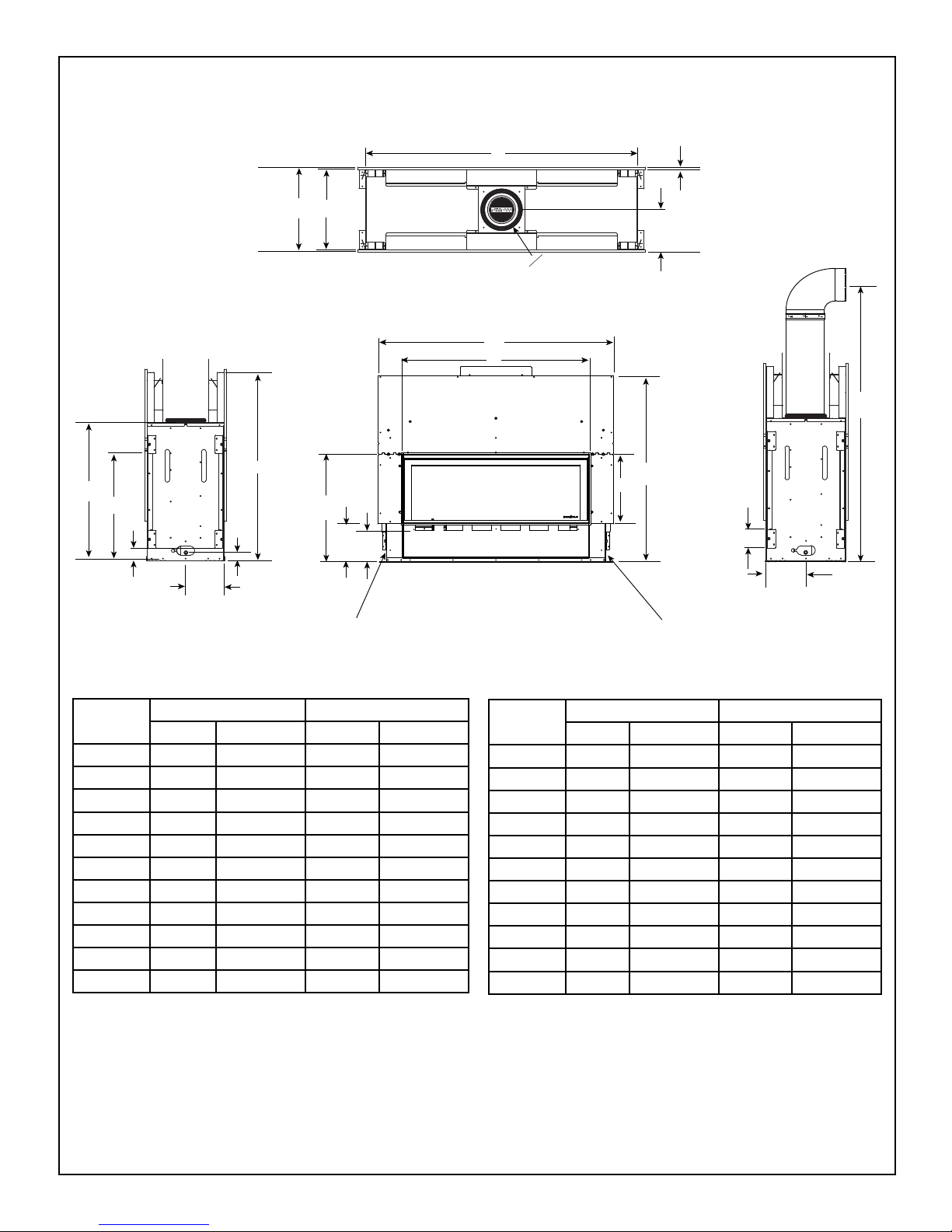
Heatilator • CRAVE4836/ST-B, CRAVE6048/ST-B, CRAVE7260/ST-B, CRAVE8472/ST-B Installation Manual • 2301-973 Rev. H • 5/17
Figure 3.3 Appliance Dimensions - CRAVE4836ST-B, CRAVE6048ST-B
Location
CRAVE4836ST-B CRAVE6048ST-B
Inches Millimeters Inches Millimeters
A 50 1270 62 1575
B 39-1/4 997 51-1/8 1299
C 15-5/8 397 15-5/8 397
D 42-1/2 1080 42-1/2 1080
E 4 102 4 102
F 8-9/16 217 8-9/16 217
G 63 1600 63 1600
H 8-9/16 217 8-9/16 217
I 1/2 13 1/2 13
J 46-3/16 1173 58 1473
K 17-1/8 435 17-1/8 435
Location
CRAVE4836ST-B CRAVE6048ST-B
Inches Millimeters Inches Millimeters
L 8 203 8 203
M 18-1/8 460 18-1/8 460
N 41-3/4 1060 41-3/4 1060
O 2-3/8 60 2-3/8 60
P 8-9/16 217 8-9/16 217
Q 24-1/2 622 24-1/2 622
R 7-1/4 184 7-1/4 184
S 8-7/8 225 8-7/8 225
T 2-3/4 70 2-3/4 70
U 23-3/4 603 23-3/4 603
V 30-1/2 775 30-1/2 775
G
K
I
M
o
O
P
E
T
H
F
J
L
N
CENTERED ON APPLIANCE
U
V
B
A
C
D
Q
S
R
GAS ACCESS
ELECTRICAL ACCESS
12
Heatilator • CRAVE4836/ST-B, CRAVE6048/ST-B, CRAVE7260/ST-B, CRAVE8472/ST-B Installation Manual • 2301-973 Rev. H • 5/17
Figure 3.4 Appliance Dimensions - CRAVE7260ST-B, CRAVE8472ST-B
Location
CRAVE7260ST-B CRAVE8472ST-B
Inches Millimeters Inches Millimeters
A 74 1880 86 2184
B 63-1/8 1603 75-1/8 1908
C 15-5/8 397 15-5/8 397
D 48-1/2 1232 48-1/2 1232
E 4 102 4 102
F 8-9/16 217 8-9/16 217
G 63 1600 75 1905
H 8-9/16 217 8-9/16 217
I 1/2 13 1/2 13
J 70 1778 82 2083
K 17-1/8 435 17-1/8 435
Location
CRAVE7260ST-B CRAVE8472ST-B
Inches Millimeters Inches Millimeters
L 8 203 8 203
M 18-1/8 460 18-1/8 460
N 47-3/4 1213 47-3/4 1213
O 2-3/8 60 2-3/8 60
P 8-9/16 217 8-9/16 217
Q 24-1/2 622 24-1/2 622
R 7-1/4 184 7-1/4 184
S 8-7/8 225 8-7/8 225
T 2-3/4 70 2-3/4 70
U 23-3/4 603 23-3/4 603
V 30-1/2 775 30-1/2 775
O
P
K
I
M
o
J
L
N
G
H
F
E
T
U
V
B
A
C
D
Q
S
R
GAS ACCESS
ELECTRICAL ACCESS
CENTERED ON APPLIANCE
13
Heatilator • CRAVE4836/ST-B, CRAVE6048/ST-B, CRAVE7260/ST-B, CRAVE8472/ST-B Installation Manual • 2301-973 Rev. H • 5/17
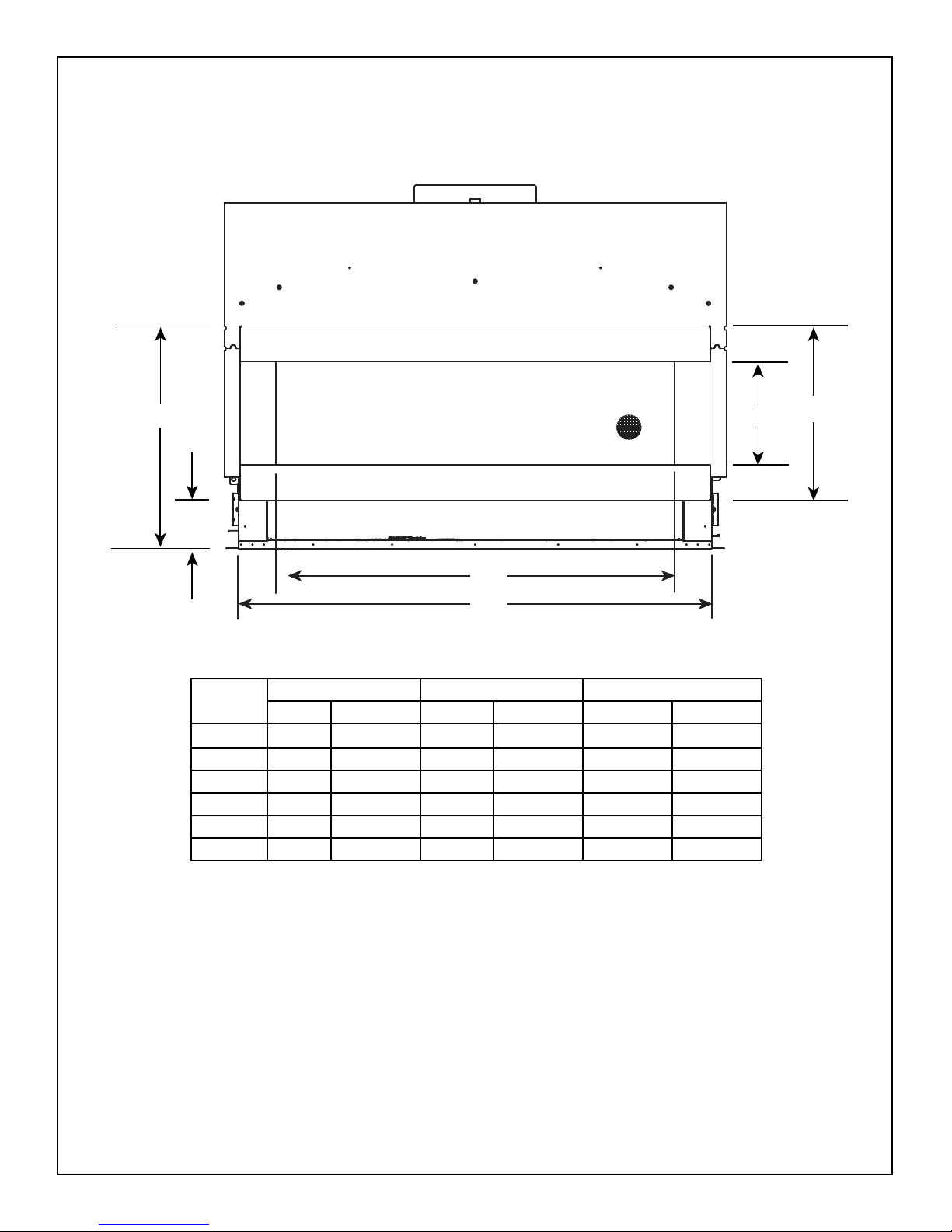
Note: See Section 10 for hearth, mantel
and nishing requirements.
The Four Square decorative front has an installed depth of 2-1/8 in. (54 mm), measured
from the front of the non-combustible nishing material to the front of the decorative front.
FOUR SQUARE DECORATIVE FRONT
Figure 3.5 Four Square (Overlap Fit) Decorative Front Dimensions
A
B
C
D
E
F
Location CRAVE4836-B CRAVE6048-B CRAVE7260-B
Inches Millimeters Inches Millimeters Inches Millimeters
A 27-5/16 694 27-5/16 694 27-5/16 692
B 5-7/8 149 5-7/8 149 5-7/8 149
C 36-3/4 933 48-3/4 1238 60-3/4 1543
D 45-5/8 1159 57-5/8 1464 69-5/8 1769
E 12-5/8 321 12-5/8 321 12-5/8 321
F 21-3/8 543 21-3/8 543 21-3/8 543
14
Heatilator • CRAVE4836/ST-B, CRAVE6048/ST-B, CRAVE7260/ST-B, CRAVE8472/ST-B Installation Manual • 2301-973 Rev. H • 5/17
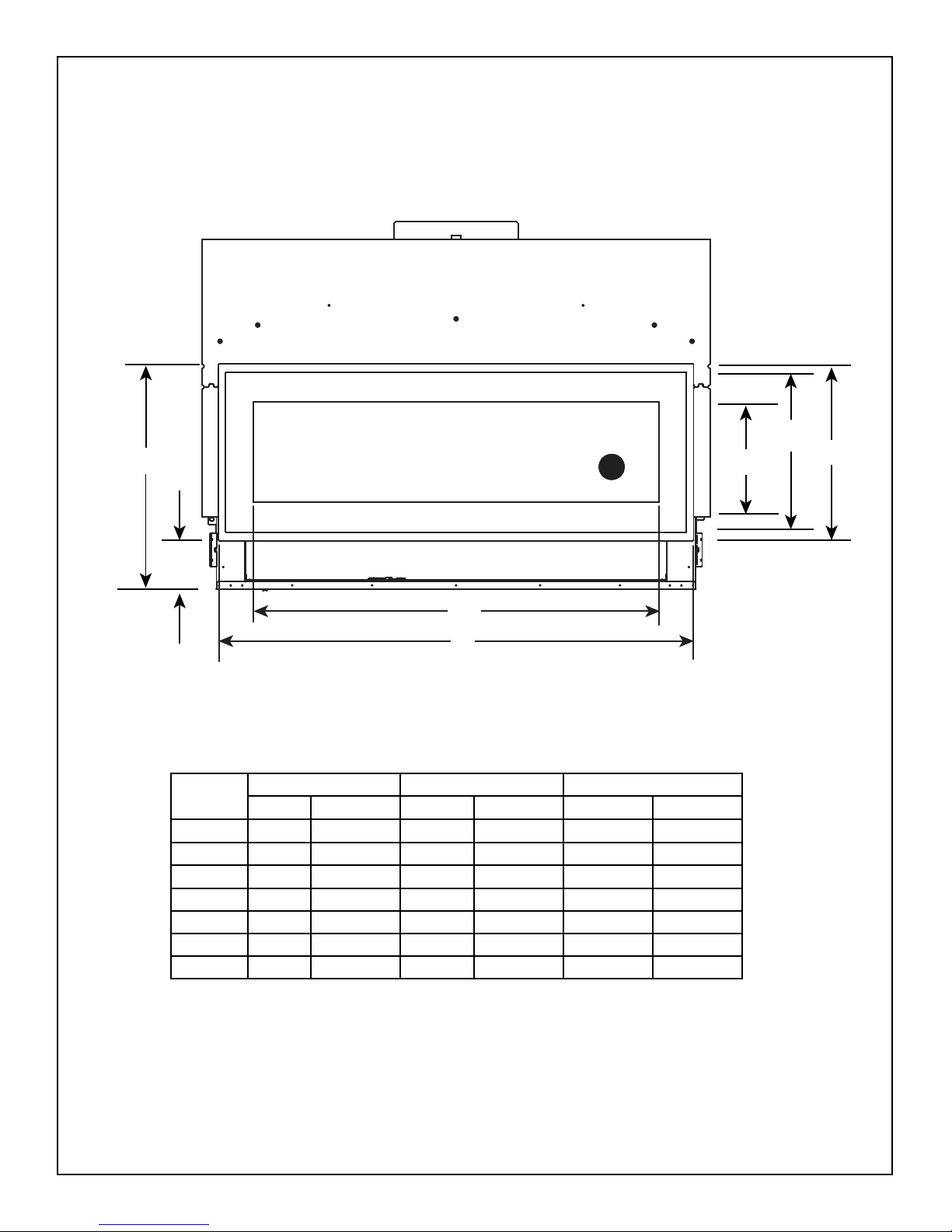
Note: See Section 10 for hearth, mantel
and nishing requirements.
The Illusion decorative front has an installed depth of 2-1/2 in. (64 mm), measured from
the front of the non-combustible nishing material to the front of the decorative front.
ILLUSION DECORATIVE FRONTS
Figure 3.6 Illusion (Overlap Fit) Decorative Front Dimensions
A
B
C
D
E
F
G
Location CRAVE4836-B CRAVE6048-B CRAVE7260-B
Inches Millimeters Inches Millimeters Inches Millimeters
A 27-5/16 694 27-5/16 694 27-5/16 692
B 5-7/8 149 5-7/8 149 5-7/8 149
C 37-3/16 945 49-1/8 1248 61-1/8 1553
D 45-1/2 1156 57-1/2 1461 69-1/2 1765
E 12-1/8 308 12-1/8 308 12-1/8 308
F 21-3/8 543 21-3/8 543 21-3/8 543
G 19-7/16 494 19-7/16 494 19-7/16 494
15
Heatilator • CRAVE4836/ST-B, CRAVE6048/ST-B, CRAVE7260/ST-B, CRAVE8472/ST-B Installation Manual • 2301-973 Rev. H • 5/17
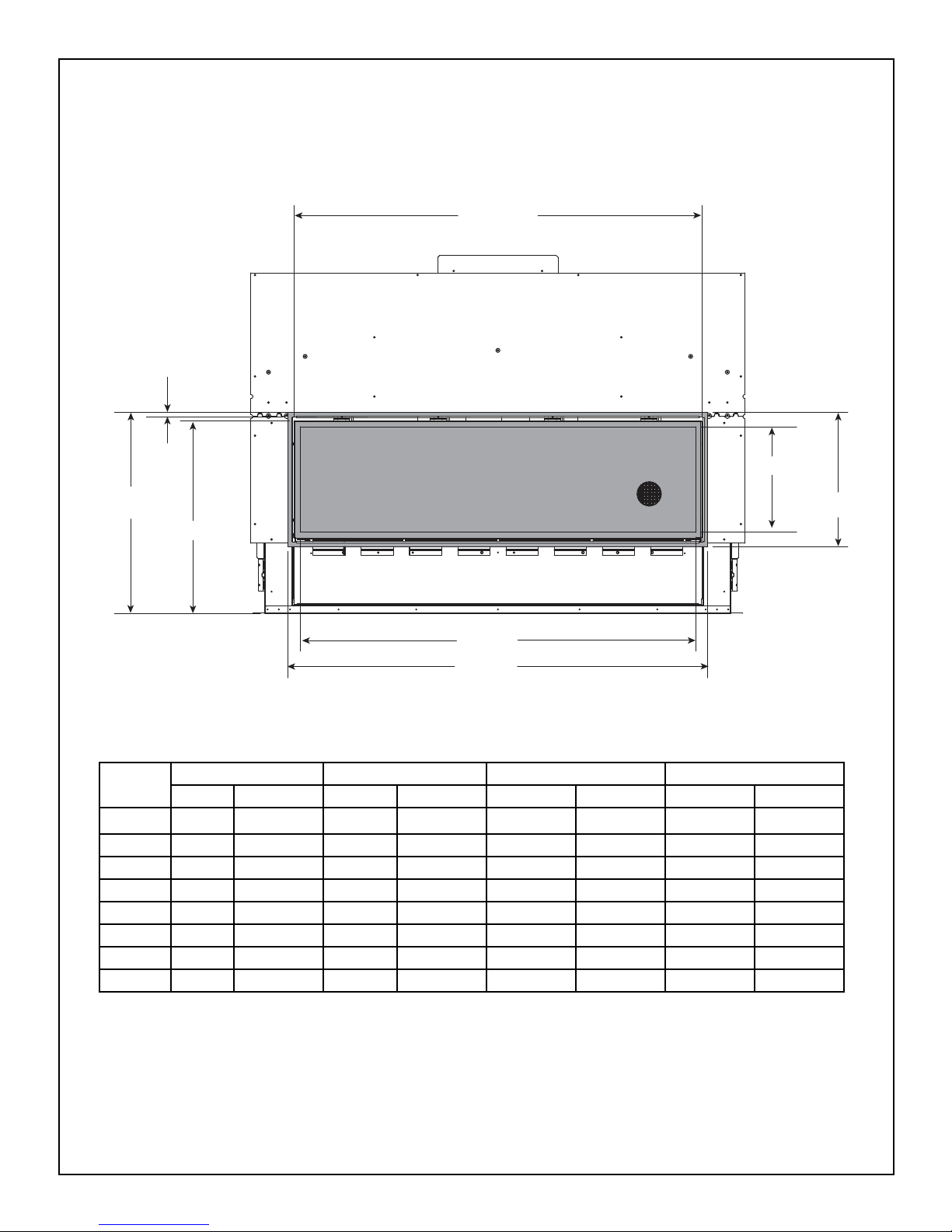
Figure 3.7 Clean Face Trim Front (Inside Fit) Decorative Front Dimensions
CLEAN FACE TRIM DECORATIVE FRONT
Location
CRAVE4836-B CRAVE6048-B CRAVE7260-B CRAVE8472-B
Inches Millimeters Inches Millimeters Inches Millimeters Inches Millimeters
A 39 991 51 1295 63 1600 75 1905
B 16-3/4 425 16-3/4 425 16-3/4 425 16-3/4 425
C 13-1/8 333 13-1/8 333 13-1/8 333 13-1/8 333
D 37-3/16 945 49-3/16 1249 61-3/16 1554 73-3/16 1859
E 40-5/16 1024 52-5/16 1329 64-5/16 1634 76-5/16 1938
F 24 610 24 610 24 610 24 610
G 5/8 16 5/8 16 5/8 16 5/8 16
H 25 635 25 635 25 635 25 635
H
F
C
B
E
A
D
G
Note: See Section 10 for hearth, mantel
and nishing requirements.
16
Heatilator • CRAVE4836/ST-B, CRAVE6048/ST-B, CRAVE7260/ST-B, CRAVE8472/ST-B Installation Manual • 2301-973 Rev. H • 5/17
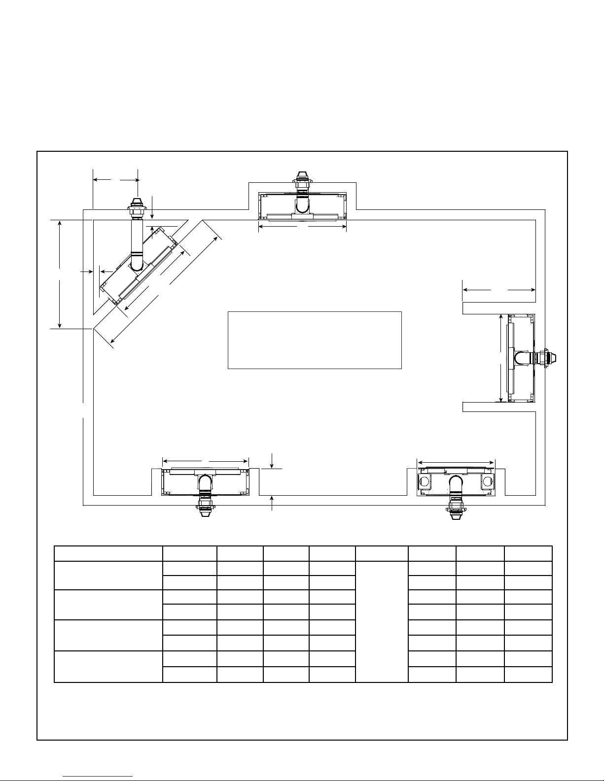
B. Clearances to Combustibles
When selecting a location for the appliance it is important
to consider the required clearances to walls. See Figure
3.8 and Figure 3.9.
WARNING! Risk of Fire or Burns! Provide adequate
clearance around air openings and for service access.
Due to high temperatures, the appliance should be lo-
cated out of trafc and away from furniture and draperies.
NOTICE: Illustrations reect typical installations and are
FOR DESIGN PURPOSES ONLY. Illustrations/diagrams
are not drawn to scale. Actual installation could vary due
to individual design preference.
Figure 3.8 Appliance Locations: CRAVE Single-Sided Models
Model A B C D E F G
CRAVE4836-B
Inches 62-1/2 48-1/4 88-1/8
See
Section
10, Figure
10.14 and
10.15.
24-1/2 18-3/4 1
Millimeters 1588 1226 2238 622 477 25
CRAVE6048-B
Inches 70-3/4 60-1/4 100-3/8 28-1/2 18-3/4 1
Millimeters 1797 1530 2550 724 476 25
CRAVE7260-B
Inches 79-1/2 72-1/4 112-3/8 31-3/4 18-3/4 1
Millimeters 2019 1835 2854 807 476 25
CRAVE8472-B
Inches 88 84-1/4 124-3/8 35-1/4 18-3/4 1
Millimeters 2235 2140 3159 895 476 25
It is important to follow the framing and nishing instructions step by step to ensure proper placement of replace
in the surrounding framing/nishing materials.
B
C
A
B
G
F
E
B
G
D
Refer to Section 10 for hearth, mantel and
wall projection information.
If a HEAT-ZONE® HEAT-DUCT will be
installed, refer to Section 5.E for information.
2 HEAT-ZONES/HEAT-DUCTS = Add 4 IN. to dimension B
1 HEAT-ZONE/HEAT DUCT = Add 2 IN. to dimension B
B
17
Heatilator • CRAVE4836/ST-B, CRAVE6048/ST-B, CRAVE7260/ST-B, CRAVE8472/ST-B Installation Manual • 2301-973 Rev. H • 5/17
C
C
B
A
D
D
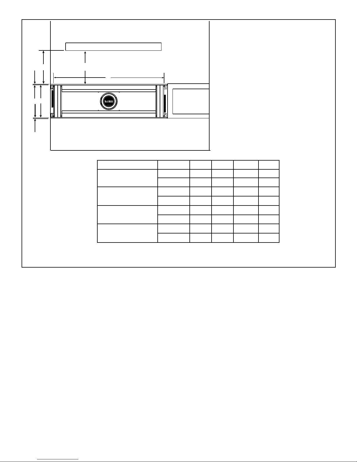
Figure 3.9 Appliance Locations: CRAVE See-Through Models
NOTICE: This See-Through appliance is NOT
designed or approved for an indoor/outdoor
application.
MODEL A B C D
CRAVE4836ST-B
Inches 48-1/4 17-1/8 48 1/2
Millimeters 1226 435 1219 13
CRAVE6048ST-B
Inches 60-1/4 17-1/8 48 1/2
Millimeters 1530 435 1219 13
CRAVE7260ST-B
Inches 72-1/4 17-1/8 48 1/2
Millimeters 1835 435 1219 13
CRAVE8472ST-B
Inches 84-1/4 17-1/8 48 1/2
Millimeters 2140 435 1219 13
18
Heatilator • CRAVE4836/ST-B, CRAVE6048/ST-B, CRAVE7260/ST-B, CRAVE8472/ST-B Installation Manual • 2301-973 Rev. H • 5/17
B
D
A
HEADER
DEPTH**
C
APPLIANCE MAY BE INSTALLED OFF OF FLOOR***
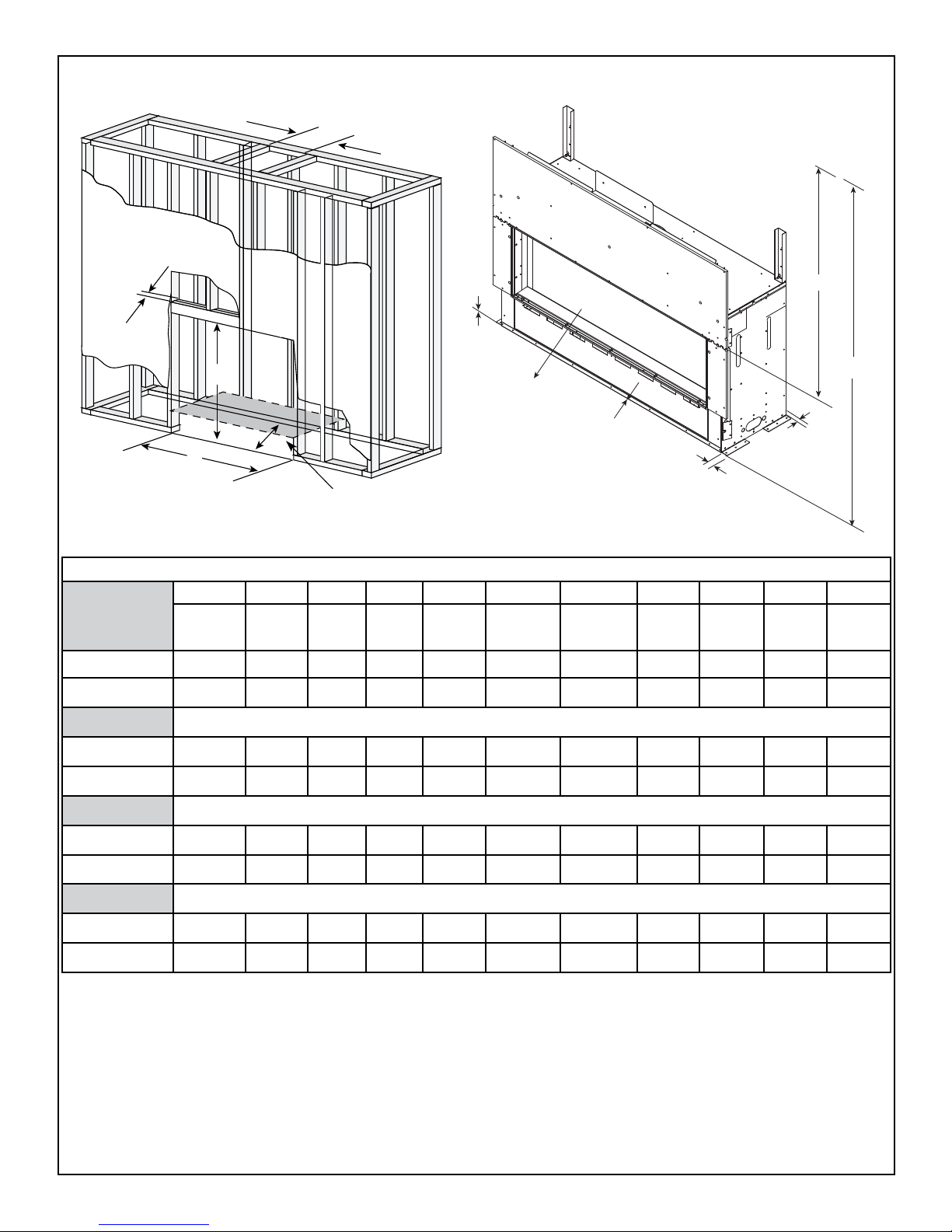
Figure 3.10 Clearances to Combustibles-CRAVE4836-B, CRAVE6048-B, CRAVE7260-B, CRAVE8472-B
MINIMUM FRAMING DIMENSIONS*
CRAVE4836-B
A B C D E F G H I J K
Rough
Opening
(Vent Pipe)
Rough
Opening
(Height)
Rough
Opening
(Depth)
Rough
Opening
(Width)
Clearance
to Ceiling
Combustible
Floor
Combustible
Flooring
Behind
Appliance
Sides of
Appliance
Front of
Appliance
Clearance
to Ceiling
Inches
10 42 18-1/4 48-1/4 31 0 0 1 1 48 55-1/2
Millimeters
254 1067 464 1226 787 0 0 25 25 1219 1410
CRAVE6048-B
Inches
10 42 18-1/4 60-1/4 31 0 0 1 1 48 55-1/2
Millimeters
254 1067 464 1530 787 0 0 25 25 1219 1410
CRAVE7260-B
Inches
10 48 18-1/4 72-1/4 31 0 0 1 1 48 55-1/2
Millimeters
254 1219 464 1835 787 0 0 25 25 1219 1410
CRAVE8472-B
Inches
10 48 18-1/4 84-1/4 31 0 0 1 1 48 55-1/2
Millimeters
254 1219 464 2140 787 0 0 25 25 1219 1410
* = Adjust framing dimensions for interior sheathing (such as sheetrock)
**= Header depth not to exceed 3-1/2 inches.
***= If appliance is installed off of oor, maintain required clearances to combustibles.
Construct platform in accordance with local building codes.
J
G
I
H
E
F
K
E=MEASUREMENT FROM TOP OF
FIREPLACE OPENING
TO CEILING
K=MEASUREMENT FROM
BOTTOM OF FIREPLACE
TO CEILING
19
Heatilator • CRAVE4836/ST-B, CRAVE6048/ST-B, CRAVE7260/ST-B, CRAVE8472/ST-B Installation Manual • 2301-973 Rev. H • 5/17
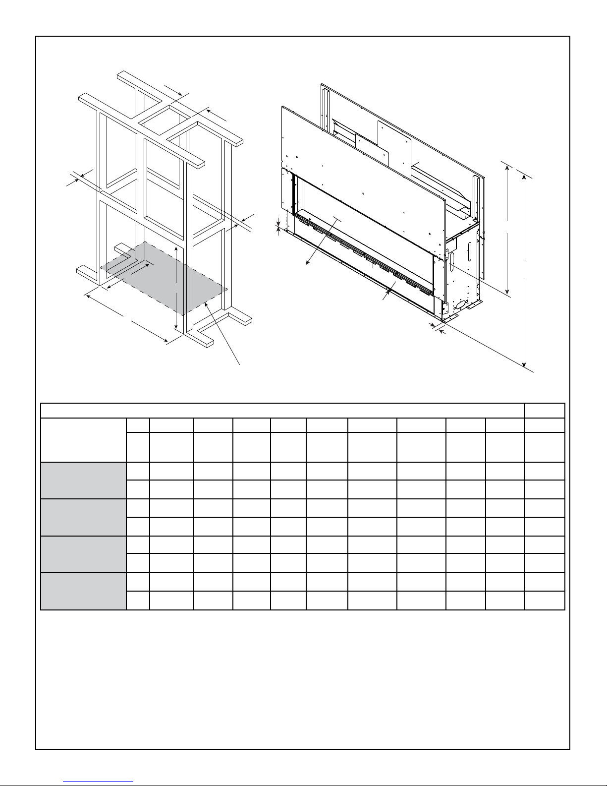
Figure 3.11 Clearances to Combustibles-CRAVE4836ST-B, CRAVE6048ST-B, CRAVE7260ST-B, CRAVE8472ST-B
MINIMUM FRAMING DIMENSIONS*
A B C D E F G H I J
Rough
Opening
(Vent Pipe)
Rough
Opening
(Height)
Rough
Opening
(Depth)
Rough
Opening
(Width)
Clearance
to Ceiling
Combustible
Floor
Combustible
Flooring
Sides of
Appliance
Front or
Rear of
Appliance
Clearance
to Ceiling
CRAVE4836ST-B
in.
10 42 17 48-1/4 31 0 0 1 48 55-1/2
mm
254 1067 432 1226 787 0 0 25 1219 1410
CRAVE6048ST-B
in.
10 42 17 60-1/4 31 0 0 1 48 55-1/2
mm
254 1067 432 1530 787 0 0 25 1219 1410
CRAVE7260ST-B
in.
10 48 17 72-1/4 31 0 0 1 48 55-1/2
mm
254 1219 432 1835 787 0 0 25 1219 1410
CRAVE8472ST-B
in.
10 48 17 84-1/4 31 0 0 1 48 55-1/2
mm
254 1219 432 2140 787 0 0 25 1219 1410
C
A
B
D
HEADER
DEPTH**
HEADER
DEPTH**
APPLIANCE MAY BE
INSTALLED OFF OF FLOOR***
* = Adjust framing dimensions for interior sheathing (such as sheetrock)
**= Header depth not to exceed 3-1/2 inches.
***= If appliance is installed off of oor, maintain required clearances to combustibles.
Construct platform in accordance with local building codes.
F
G
H
E
I
J
E=MEASUREMENT FROM TOP
OF FIREPLACE OPENING
TO CEILING
J=MEASUREMENT FROM
BOTTOM OF FIREPLACE
TO CEILING
20
Heatilator • CRAVE4836/ST-B, CRAVE6048/ST-B, CRAVE7260/ST-B, CRAVE8472/ST-B Installation Manual • 2301-973 Rev. H • 5/17
D. Floor Protection
NOTICE: Install appliance on hard metal or wood surfaces
extending full width and depth. DO NOT install directly
on carpeting, vinyl, tile or any combustible material other
than wood.
WARNING! Risk of Fire! Maintain specied air space
clearances to appliance and vent pipe:
• Insulation and other materials must be secured to prevent
accidental contact.
• The chase must be properly blocked to prevent blown
insulation or other combustibles from entering and
making contact with replace or chimney.
• Failure to maintain airspace could cause overheating
and re.
Figure 3.12 Floor Protection
C. Constructing the Appliance Chase
A chase is a vertical box-like structure built to enclose the
gas appliance and/or its vent system. In cooler climates
the vent should be enclosed inside the chase.
NOTICE: Treatment of ceiling restops and wall shield
restops and construction of the chase may vary with the
type of building. These instructions are not substitutes
for the requirements of local building codes. Therefore,
you MUST check local building codes to determine the
requirements to these steps.
Chases should be constructed in the manner of all outside walls of the home to prevent cold air drafting prob-
lems. The chase should not break the outside building
envelope in any manner.
Walls, ceiling, base plate and cantilever oor of the chase
should be insulated. Vapor and air inltration barriers
should be installed in the chase as per regional codes for
the rest of the home. Additionally, in regions where cold
air inltration may be an issue, the inside surfaces may be
sheetrocked and taped (or an equivalent method may be
used) to achieve maximum air tightness.
To further prevent drafts, the wall shield and ceiling restops should be caulked with caulk with a minimum of
300 ºF continuous exposure rating to seal gaps. Gas line
holes and other openings should be caulked with caulk
with a minimum of 300 ºF continuous exposure rating or
stuffed with unfaced insulation. If the appliance is being
installed on a cement surface, a layer of plywood may be
placed underneath to prevent conducting cold up into the
room.
Note: Figure 3.10 and Figure 3.11, and Figure 3.12 show the
replace installed on the oor. However, this replace can be
elevated off the oor provided that the replace is properly
supported by framing materials and the ceiling clearances are
maintained.
21
Heatilator • CRAVE4836/ST-B, CRAVE6048/ST-B, CRAVE7260/ST-B, CRAVE8472/ST-B Installation Manual • 2301-973 Rev. H • 5/17
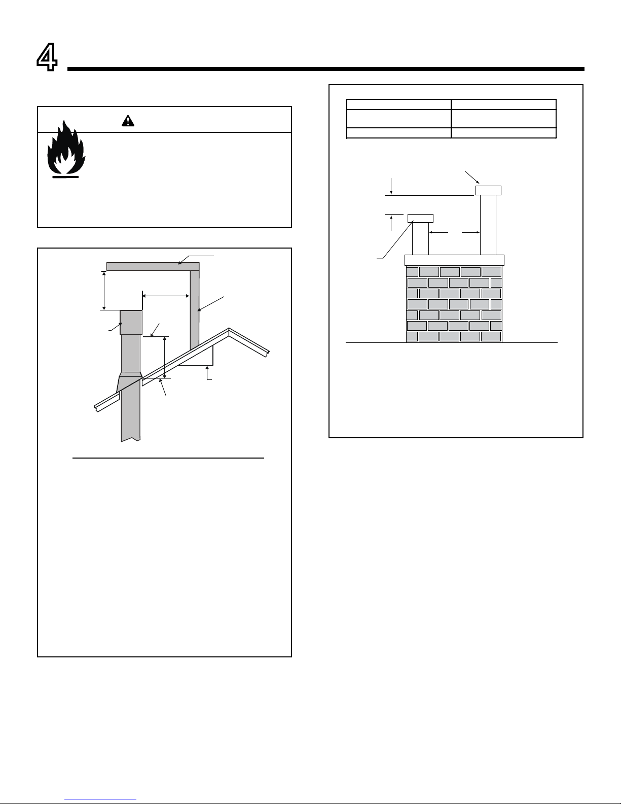
A. Vent Termination Minimum Clearances
Roof Pitch H (Min.) Ft.
Flat to 6/12...........................................................1.0*
Over 6/12 to 7/12 .................................................1.25*
Over 7/12 to 8/12 .................................................1.5*
Over 8/12 to 9/12 .................................................2.0*
Over 9/12 to 10/12 ...............................................2.5*
Over 10/12 to 11/12 .............................................3.25
Over 11/12 to 12/12 .............................................4.0
Over 12/12 to 14/12 .............................................5.0
Over 14/12 to 16/12 .............................................6.0
Over 16/12 to 18/12 .............................................7.0
Over 18/12 to 20/12 .............................................7.5
Over 20/12 to 21/12 .............................................8.0
Figure 4.1 Minimum Height From Roof To Lowest Discharge
Opening
HORIZONTAL
OVERHANG
VERTICAL
WALL
GAS DIRECT VENT
TERMINATION CAP
12
X
ROOF PITCH
IS X/ 12
LOWEST
DISCHARGE
OPENING
2 FT.
MIN.
20 INCHES MIN.
H (MIN.) - MINIMUM HEIGHT FROM ROOF
TO LOWEST DISCHARGE OPENING
4
Termination Location and Vent Information
Fire Risk.
Maintain vent clearance to combustibles as
specied.
• DO NOT pack air space with insulation or other
materials.
Failure to keep insulation or other materials away
from vent pipe could cause overheating and re.
WARNING
Figure 4.2 Staggered Termination Caps
Gas, Wood or Fuel Oil
Termination Cap
B
Gas
Termination
Cap **
A *
*
If using decorative cap cover(s), this distance may need to be
increased. Refer to the installation instructions supplied with the
decorative cap cover.
**
A B
6 in. (minimum) up to 20 in.
152 mm/508 mm
18 in. minimum
457 mm
20 in. and over 0 in. minimum
In a staggered installation with both gas and wood or fuel oil
terminations, the wood or fuel oil termination cap must be
higher than the gas termination cap.
* H minimum may vary depending on regional snowfall.
Refer to local codes.
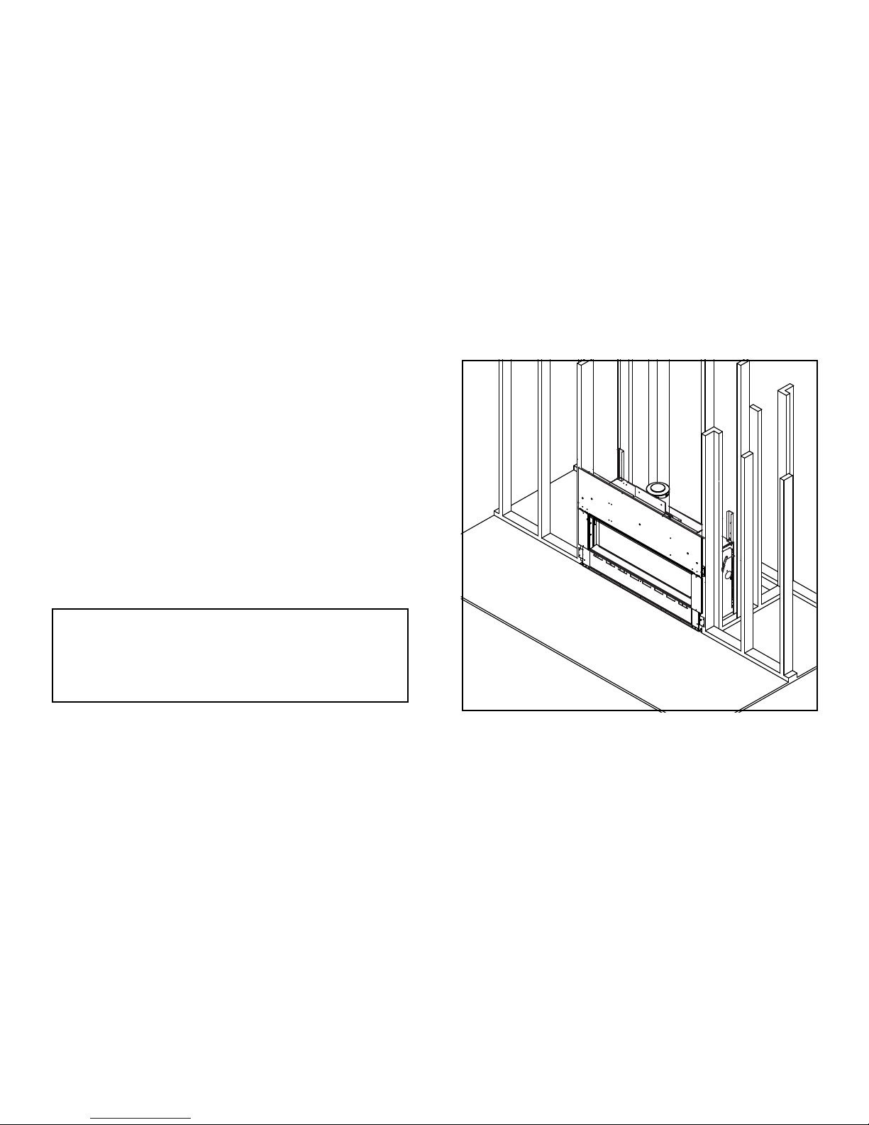
 Loading...