

Heatilator CNXT70PLUS Owner's Manual
Models:
CNXT70PLUS
Fresh Air Fireplace
Owner’s Manual
Installation and Operation
Refractory must be ordered separately.
CAUTION
DO NOT DISCARD THIS MANUAL
•
• Important operating and
maintenance instructions
included.
Read, understand and follow
these instructions for safe
installation and operation.
WARNING
If the information in these instructions is not followed exactly, a
fi re may result causing property
damage, personal injury, or death.
• Do not store or use gasoline or other fl ammable vapors and liquids in the vicinity of
this or any other appliance.
• What to do if you smell gas:
- Do not try to light any appliance.
- Do not touch any electrical switch. Do not
use any phone in your building.
- Immediately call your gas supplier from
a neighbor’s phone. Follow the gas
supplier’s instructions.
- If you cannot reach your gas supplier, call
the fi re department.
• Installation and service must be performed
by a qualifi ed installer, service agency, or
the gas supplier.
DO NOT
DISCARD
•
Leave this manual with
party responsible for
use and operation.
WARNING
HOT! DO NOT TOUCH.
SEVERE BURNS MAY RESULT.
CLOTHING IGNITION MAY RESULT.
Glass and other surfaces are hot during
operation and cool down.
• Keep children away.
• CAREFULLY SUPERVISE children in same room as
appliance.
• Alert children and adults to hazards of high
temperatures.
• Do NOT operate with protective barriers removed or
door open.
• Keep clothing, furniture, draperies and other
combustibles away.
In the Commonwealth of Massachusetts:
• installation must be performed by a licensed plumber or gas fi tter.
• a CO detector shall be installed in the room where the appliance is
installed.
Installation and service of this appliance should be performed
by qualified personnel. Hearth & Home Technologies
suggests NFI certifi ed or factory-trained
professionals, or technicians supervised
by an NFI certifi ed professional.
Hearth & Home Technologies • CNXT70PLUS • 4034-105 Rev C • 09/05 1
Read this manual before installing or operating this appliance.
Please retain this owner’s manual for future reference.
Congratulations
Congratulations on selecting a Heatilator Home Products gas
appliance—an elegant and clean alternative to wood burning
appliances. The Heatilator Home Products gas appliance you
have selected is designed to provide the utmost in safety,
reliability, and effi ciency.
As the owner of a new appliance, you’ll want to read and
carefully follow all of the instructions contained in this owner’s
manual. Pay special attention to all cautions and warnings.
This owner’s manual should be retained for future reference.
We suggest you keep it with your other important documents
and product manuals.
The information contained in this owner’s manual, unless
noted otherwise, applies to all models and gas control
systems.
Your new Heatilator Home Products gas appliance will
give you years of durable use and trouble-free enjoyment.
Welcome to the Heatilator Home Products family of appliance
products!
We recommend that you record the following pertinent
Homeowner Reference Information
information about your appliance:
Model Name: Date purchased/installed:
Serial Number: Location on appliance:
Dealership purchased from: Dealer phone:
Notes:
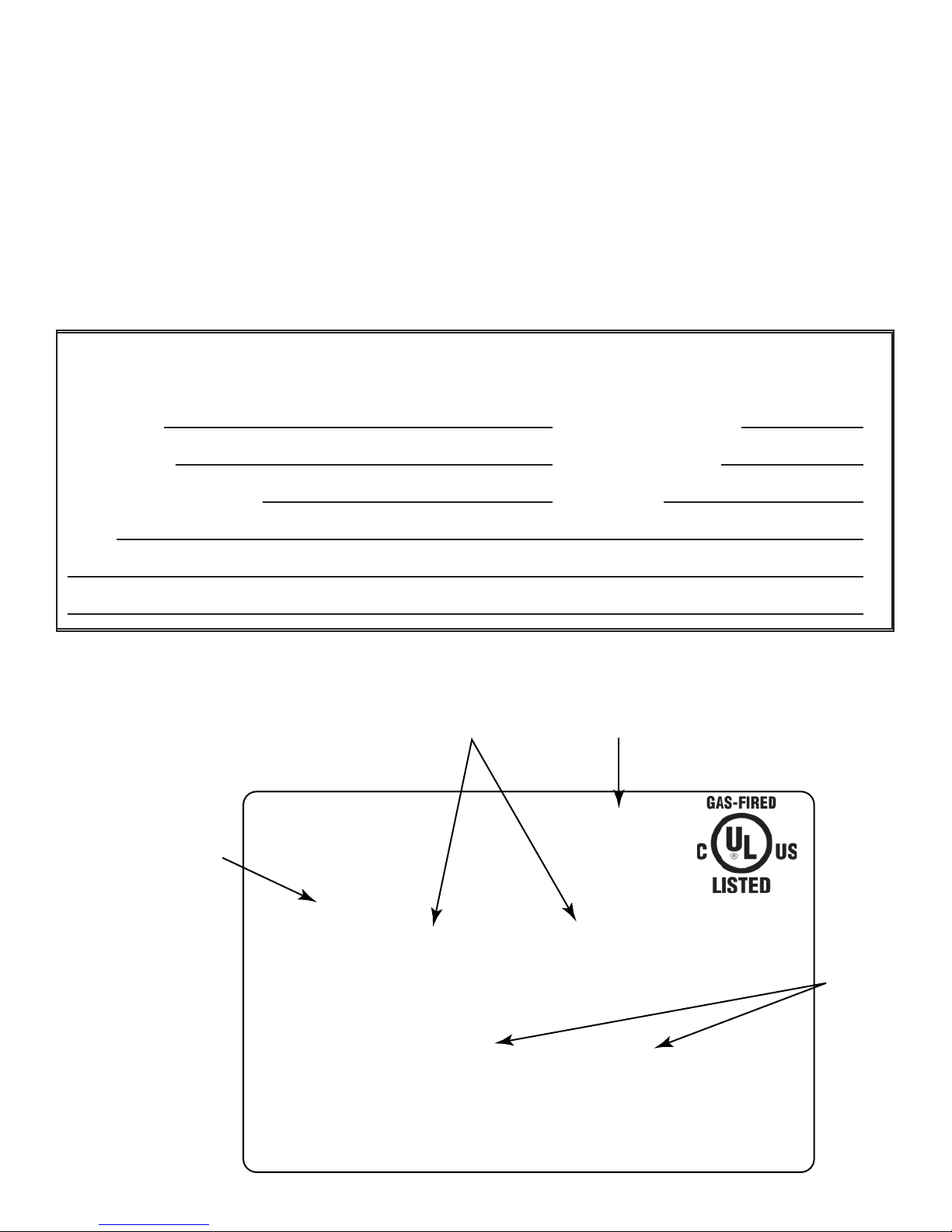
Listing Label Information/Location
The model information regarding your specifi c appliance can be found on the rating plate located in the control area of the
appliance.
Serial #
XXXXXXXXX
XXXX
CERTIFIED
FOR CANADA
CERTIFIÉ POUR LE
CANADA
Orifice
Size
Model #
Gas Type
Hearth & Home Technologies Inc
1915 W. Saunders Street
Mt. Pleasant, IA 52641
ANSI Standard
MODEL MFG. DATE
MODÈLE DATE DE FAB.
GAS TYPE/TYPE DE GAZ NATURAL/NATUREL PROPANE
ALTITUDE 0-2000 2000-4000 FT/PI 0-2000 2000-4000 FT/PI
MAX INPUT/DÉBIT XX,XXX XX,XXX BTUH XX,XXX XX,XXX BTUH
MIN INPUT/DÉBIT XX,XXX XX,XXX BTUH XX,XXX XX,XXX BTUH
MANIFOLD PRESSURE/PRESSION TUBULAIRE
MAX. XX IN. W.C./C. D'EAU XX IN. W.C./C. D'EAU
MIN. XX IN. W.C./C. D'EAU XX IN. W.C./C. D'EAU
MIN. INLET PRESS. XX IN. W.C./C. D'EAU 1XX IN. W.C./C. D'EAU
FOR THE PURPOSE OF INPUT ADJUSTMENT
PRESS. MIN. D'ALIMENTATION
ORIFICE SIZE
DIAM. DE L'INJECTEUR XX/XX DIA. in./mm XX/XX DIA. in./mm
XXXXXX
SERIAL
NO. DE SÉRIE
LESS THAN/MOINS DE 3 AMPÈRES., 115V., 60 Hz
DO NOT REMOVE OR COVER THIS LABEL.
VENTED GAS FIREPLACE - NOT FOR USE WITH SOLID FUEL.
FOYER À GAZ À ÉVACUATION - NE DOIT PAS ÊTRE UTILISÉ
AVEC UN COMBUSTIBLE SOLIDE.
2 Hearth & Home Technologies • CNXT70PLUS • 4034-105 Rev C • 09/05

Table of Contents
1 Listing and Code Approvals 4
A. Appliance Certifi cation . . . . . . . . . . . . . . . . . . . . . . . . . 4
B. BTU Specifi cations . . . . . . . . . . . . . . . . . . . . . . . . . . . 4
C. High Altitude Installations . . . . . . . . . . . . . . . . . . . . . .4
E. Non-Combustible Materials . . . . . . . . . . . . . . . . . . . . . 4
F. Combustible Materials . . . . . . . . . . . . . . . . . . . . . . . . . 4
2 Getting Started 5
A. Design and Installation Considerations . . . . . . . . . . . . 5
B. Tools and Supplies Needed . . . . . . . . . . . . . . . . . . . . . 5
C. Inspect the Appliance and Components . . . . . . . . . . . 5
3 Framing and Clearances 6
A. Select Appliance Location . . . . . . . . . . . . . . . . . . . . . . 6
B. Construct the Appliance Chase . . . . . . . . . . . . . . . . . . 7
C. Clearances . . . . . . . . . . . . . . . . . . . . . . . . . . . . . . . . .8
D. Mantel Projections . . . . . . . . . . . . . . . . . . . . . . . . . . . . 8
4 Termination Locations 9
A. Vent Termination Minimum Clearances . . . . . . . . . . . . 9
5 Vent Information and Diagrams 9
6 Appliance Preparation 10
A. Securing and Leveling the Appliance . . . . . . . . . . . .10
7 Gas Information 11
A. Fuel Conversion . . . . . . . . . . . . . . . . . . . . . . . . . . . . 11
B. Gas Pressure . . . . . . . . . . . . . . . . . . . . . . . . . . . . . . 11
C. Gas Connection . . . . . . . . . . . . . . . . . . . . . . . . . . . . . 11
D. High Altitude Installations . . . . . . . . . . . . . . . . . . . . .12
8 Electrical Information 13
A. Recommendation for Wire . . . . . . . . . . . . . . . . . . . . . 13
B. Connecting to the Appliance . . . . . . . . . . . . . . . . . . . 13
C. System Wiring . . . . . . . . . . . . . . . . . . . . . . . . . . . . . . 14
D. Wall Switch . . . . . . . . . . . . . . . . . . . . . . . . . . . . . . . .17
E. Optional Accessories Requirements . . . . . . . . . . . . .17
F. Junction Box Installation . . . . . . . . . . . . . . . . . . . . . . 18
9 Finishing 19
A. Mantel Projections . . . . . . . . . . . . . . . . . . . . . . . . . . . 19
B. Facing Material . . . . . . . . . . . . . . . . . . . . . . . . . . . . . 19
10 Appliance Setup 20
A. Install the Refractory . . . . . . . . . . . . . . . . . . . . . . . . . 20
B. Log Assembly . . . . . . . . . . . . . . . . . . . . . . . . . . . . . . 20
C. Place the Silica Rock (Techno Sil) . . . . . . . . . . . . . . . 20
D. Place the Lava Rock . . . . . . . . . . . . . . . . . . . . . . . . .20
11 Operating Instructions 21
A. Sequence of Operation . . . . . . . . . . . . . . . . . . . . . . . 21
B. Lighting the Appliance . . . . . . . . . . . . . . . . . . . . . . . . 23
C. After the Appliance is Lit . . . . . . . . . . . . . . . . . . . . . . 24
12 Troubleshooting 25
13 Maintaining and Servicing the Appliance 26
A. Annual Maintenance . . . . . . . . . . . . . . . . . . . . . . . . . 26
B. Cleaning the Burner and Control Compartment . . . .26
C. HRV200PLUS . . . . . . . . . . . . . . . . . . . . . . . . . . . . . .26
D. Ember Bed Bulb Replacement . . . . . . . . . . . . . . . . . 26
E. Log Removal/Replacement . . . . . . . . . . . . . . . . . . . . 26
14 Reference Materials 27
A. Appliance Dimension Diagram . . . . . . . . . . . . . . . . .27
B. Service Parts List . . . . . . . . . . . . . . . . . . . . . . . . . . . 28
C. Optional Components . . . . . . . . . . . . . . . . . . . . . . . . 33
D. Limited Lifetime Warranty . . . . . . . . . . . . . . . . . . . . . 35
E. Contact Information . . . . . . . . . . . . . . . . . . . . . . . . . . 36
Note: An arrow () found in the text signifi es change in content.
Hearth & Home Technologies • CNXT70PLUS • 4034-105 Rev C • 09/05 3
Listing and Code Approvals
1
A. Appliance Certifi cation
MODELS: CNXT70PLUS
LABORATORY: Underwriters Laboratories, Inc. (UL)
TYPE: Vented Gas Appliance
STANDARD: ANSI Z21.50-2000 • ANSI Z21.47-1998 •
CSA 2.22-2000 • CGA 2.3-M98
NOT INTENDED FOR USE AS A PRIMARY HEAT
SOURCE. This appliance is tested and approved as either
supplemental room heat or as a decorative appliance. It
should not be factored as primary heat in residential heating
calculations.
Note: This installation must conform with local codes. In the
absence of local codes you must comply with the National
Fuel Gas Code, ANSI Z223.1-latest edition in the U.S.A.
and the CAN/CGA B149 Installation Codes in Canada.
B. BTU Specifi cations
Max Input
Model
CNXT70PLUS-LP Front 43,500 33,000 .039 in./.99 mm
Back .066 in./1.68 mm
CNXT70PLUS-NG Front 47,000 34,000 .059 in./1.49 mm
Back .117 in/2.97 mm
BTUH
Min Input
BTUH Orifi ce Size
C. High Altitude Installations
The CNXT70PLUS is power vented. High altitude gas appliance considerations are no longer of concern, as long as the
gas appliance is properly installed with the HRV200PLUS
properly balanced (refer to HRV200PLUS manual).
Note: This appliance CANNOT be installed at an elevation
above 6,200 ft (1,890 meters)
WARNING
WARNING
This is a power-vented gas appliance. Do not burn
wood or materials other than as listed on the rating
plate in this fresh air fi replace.
Do NOT use this appliance if any part has been under
water. Immediately call a qualifi ed service technician
to inspect the appliance and to replace any part of the
control system and any gas control which has been
under water.
E. Non-Combustible Materials
Materials that are reported as passing ASTM E 136, Standard Test Method for Behavior of Materials in a Vertical
Tube Furnace at 750° C, shall be considered non-combus-
tible materials.
F. Combustible Materials
Materials made of or surfaced with wood, compressed paper, plant fi bers, plastics, or other material that can ignite and
burn, whether fl ame proofed or not, or whether plastered or
unplastered shall be considered combustible materials.
4 Hearth & Home Technologies • CNXT70PLUS • 4034-105 Rev C • 09/05

Getting Started
2
A. Design and Installation Considerations
Heatilator Home Products vented gas appliances are designed to operate with all exhaust gases expelled to the outside of the building.
CAUTION
CAUTION
Sharp Edges
• Wear protective gloves and safety
glasses during installation.
Check building codes prior to installation.
• Installation MUST comply with local, regional,
state and national codes and regulations.
• Consult insurance carrier, local building, fire
offi cials or authorities having jurisdiction about
restrictions, installation inspection, and permits.
When planning an appliance installation, it’s necessary to
determine the following information before installing:
• Where the appliance is to be installed.
• The vent system confi guration to be used.
• Gas supply piping.
• Electrical wiring.
• Framing and fi nishing details.
• Whether optional accessories—devices such as a fan,
wall switch, or remote control—are desired.
WARNING
Keep appliance dry.
• Mold or rust may cause
odors.
• Water may damage controls.
C. Inspect the Appliance and Components
WARNING
Inspect appliance and components for
damage. Damaged parts may impair safe
operation.
• Do NOT install damaged components.
• Do NOT install incomplete components.
• Do NOT install substitute components.
Report damaged parts to dealer.
• Carefully remove the appliance and components from the
packaging.
• The vent system components and trim doors are shipped
in separate packages.
• The gas logs may be packaged separately and must be
fi eld installed.
• Report to your dealer any parts damaged in shipment,
particularly the condition of the glass.
• Read all of the instructions before starting the
installation. Follow these instructions carefully
during the installation to ensure maximum safety and
benefi t.
WARNING
B. Tools and Supplies Needed
Before beginning the installation be sure that the following
tools and building supplies are available.
Reciprocating saw Framing material
Pliers Hi temp caulking material
Hammer Gloves
Phillips screwdriver Framing square
Flat blade screwdriver Electric drill and bits (1/4 in.)
Plumb line Safety glasses
Level Manometer
Voltmeter Tape measure
Non-corrosive leak check solution
1/2 - 3/4 in. length, #6 or #8 Self-drilling screws
One 1/4 in. female connection (for optional fan).
Hearth & Home Technologies • CNXT70PLUS • 4034-105 Rev C • 09/05 5
Hearth & Home Technologies disclaims any
responsibility for, and the warranty will be
voided by, the following actions:
• Installation and use of any damaged appliance or
vent system component.
• Modifi cation of the appliance or vent system.
• Installation other than as instructed by Hearth & Home
Technologies.
• Improper positioning of the gas logs or the glass
door.
• Installation and/or use of any component part not
approved by Hearth & Home Technologies.
Any such action may cause a fi re hazard.
Framing and Clearances
3
Note:
• Illustrations refl ect typical installations and are FOR
DESIGN PURPOSES ONLY.
• Illustrations/diagrams are not drawn to scale.
• Actual installation may vary due to individual design
preference.
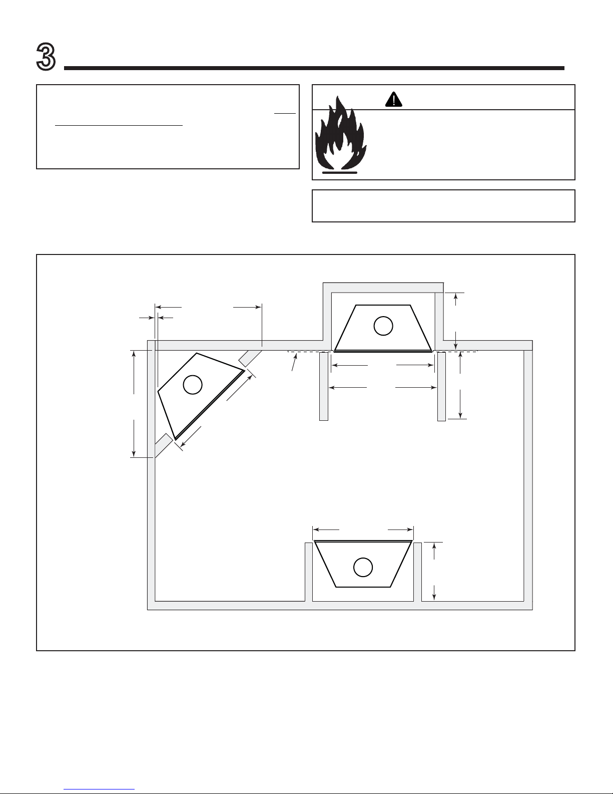
A. Select Appliance Location
When selecting a location for your appliance it is important to
consider the required clearances to walls (See Figure 3.1).
WARNING
Fire Risk
Provide adequate clearance:
• Around air openings.
• For service access.
Locate appliance away from traffi c areas.
Note: For actual appliance dimensions refer to
Section 14.
1/2 in. (13 mm)
min.
appliance
to combustibles
50-5/8 in.
(1286 mm)
50-5/8 in.
(1286 mm)
42 in.
(1067 mm)
23-1/2 in.
(597 mm)
42 in.
Drywall
In addition to these framing dimensions, also reference the
following sections:
• Clearances and Mantel Projections (Sections 3.C. and 3.D.)
• Vent Clearances and Framing (Section 6)
(1067 mm)
43 in.
(1092 mm)
Alcove
Installation
42 in.
(1067 mm)
23-1/2 in.
(597 mm)
48 in.
(1219 mm max.)
Figure 3.1 Appliance Locations
6 Hearth & Home Technologies • CNXT70PLUS • 4034-105 Rev C • 09/05
B. Construct the Appliance Chase
A chase is a vertical boxlike structure built to enclose the gas
appliance and/or its vent system. Vertical vents that run on
the outside of a building may be, but are not required to be,
installed inside a chase.
Construction of the chase may vary with the type of building. These instructions are not substitutes for the requirements of local building codes. Local building codes MUST
be checked.
Chases should be constructed in the manner of all outside
walls of the home to prevent cold air drafting problems. The
chase should not break the outside building envelope in any
manner.
Walls, ceiling, base plate and cantilever fl oor of the chase
should be insulated. Vapor and air infi ltration barriers should
be installed in the chase as per regional codes for the rest of
the home. Additionally, in reagions where cold air infi ltration
may be an issure, the inside surfaces be sheetrocked and
taped for maximum air tightness.
To further prevent drafts, the ceiling fi restops should be
caulked with high temperature caulk to seal gaps. Gas line
holes and other openings should be caulked with high temperature caulk or stuffed with unfaced insulation. If the appliance is being installed on a cement slab, a layer of plywood
may be placed underneath to prevent conducting cold up
into the room.
WARNING
Fire Risk
• Construct chase to all clearance
specifi cations in manual.
• Locate and install appliance to all
clearance specifi cations in manual.
WARNING
Fire Risk
Odor Risk
• Install appliance on hard metal or wood
surfaces extending full width and depth
of appliance.
• Do NOT install appliance directly on
carpeting, vinyl, tile or any combustible
material other than wood.
Hearth & Home Technologies • CNXT70PLUS • 4034-105 Rev C • 09/05 7
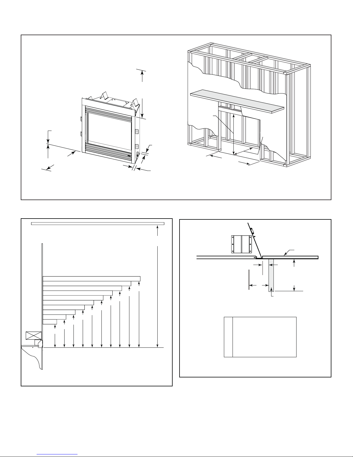
C. Clearances
0 in.
to floor
32-7/8 in.
(835 mm)
1/2 in.
(13 mm)
38-3/4 in.
(984 mm)
23-1/2 in.
(597 mm)
0 in. to combustibles
in front of the FAF
Figure 3.2 Clearances to Combustibles
D. Mantel Projections
6
5
4
3
13-3/4
13-3/4
10-3/4
Measured from top of fireplace opening (in inches)
16-3/4
13-3/4
7
8
16-3/4
9
16-3/4
32-7/8 in. minimum
11
10
19-3/4
19-3/4
to ceiling
12
19-3/4
0 in.
(1067 mm)
Top of
Appliance
42 in.
A
B
1 in. (25 mm) min.
A
to perpendicular wall
3-1/2 in. (89 mm) min.
B
from fireplace opening
to perpendicular wall
Drywall
48 in.
(1219 mm)
max.
Mantel Leg or
Perpendicular Wall
Figure 3.3 Clearances to Mantels or Other Combustibles Above
Appliance
8 Hearth & Home Technologies • CNXT70PLUS • 4034-105 Rev C • 09/05
Figure 3.4 Clearances to Mantel Legs or Wall Projections (Accept-
able on both sides of opening)
Termination Locations
4
A. Vent Termination Minimum Clearances
WARNING
Fire Risk
Explosion Risk
Maintain vent clearance to combustibles as
specifi ed.
• Do not pack air space with insulation or
other materials.
Failure to keep insulation or other materials
away from vent pipe may cause fi re.
Note: Refer to the HRV200PLUS installation manual for
additional installation and venting instructions.
Vent Information and Diagrams
5
WARNING
Fire Risk
Fumes Risk
This unit MUST be vented with the
HRV200PLUS.
• Do not connect to a chimney fl ue.
The CNXT70PLUS will not vent
correctly unless it is connected to the
HRV200PLUS.
Note: Refer to the HRV200PLUS installation manual for
additional installation and venting instructions.
Hearth & Home Technologies • CNXT70PLUS • 4034-105 Rev C • 09/05 9
Appliance Preparation
6
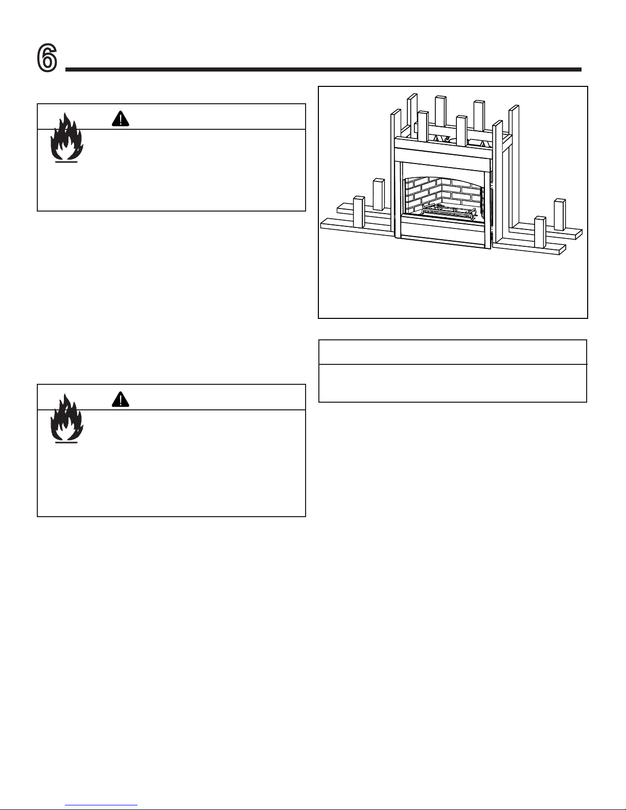
A. Securing and Leveling the Appliance
Fire Risk!
• Prevent contact with sagging, loose
• Do NOT install against combustible
The diagram shows how to properly position, level, and secure the appliance. Nailing tabs are provided to secure the
appliance to the framing members.
• Place the appliance into position.
• Level the appliance from side to side and front to back.
• Shim the appliance as necessary. It is acceptable to use
wood shims.
• Bend out nailing tabs on each side.
• Keep nailing tabs fl ush with the framing.
• Secure the appliance to the framing by using nails or
screws through the nailing tabs.
WARNING
insulation.
materials such as exposed insulation,
plastic and insulation backer.
WARNING
Figure 6.1 Proper Positioning, Leveling and Securing of an
Appliance
CAUTION
Do NOT notch into the framing around the appliance
spacers.
Fire Risk
• ALWAYS maintain specifi ed clearances
around the appliance.
• Do NOT notch into the framing around
the appliance spacers.
Failure to keep insulation or other materials
away from vent pipe may cause fi re.
10 Hearth & Home Technologies • CNXT70PLUS • 4034-105 Rev C • 09/05
 Loading...