

Heatilator CNXT4236IFTT, CNXT4236IFTH, CNXT4236IFTSG, CNXT4842IFTT, CNXT4842IFTH Installation Manual
...
Installation Manual
Installation and Appliance Setup
INSTALLER: Leave this manual with party responsible for use and operation.
OWNER: Retain this manual for future reference.
NOTICE: DO NOT discard this manual!
Models:
CNXT4236IFTT
CNXT4236IFTH
CNXT4236IFTSG
CNXT4842IFTT
CNXT4842IFTH
CNXT4842IFTSG
WARNING:
FIRE OR EXPLOSION HAZARD
Failure to follow safety warnings exactly
could result in serious injury, death, or
property damage.
• DO NOT store or use gasoline or other am-
mable vapors and liquids in the vicinity of this
or any other appliance.
• What to do if you smell gas
- DO NOT try to light any appliance.
- DO NOT touch any electrical switch. DO
NOT use any phone in your building.
- Leave the building immediately.
- Immediately call your gas supplier from
a neighbor’s phone. Follow the gas supplier’s instructions.
- If you cannot reach your gas supplier, call
the re department.
• Installation and service must be performed
by a qualied installer, service agency, or the
gas supplier.
This appliance may be installed as an OEM
installation in manufactured home (USA
only) or mobile home and must be installed
in accordance with the manufacturer’s
instructions and the Manufactured Home
Construction and Safety Standard, Title 24
CFR, Part 3280 in the United States, or the
Standard for Installation in Mobile Homes,
CAN/CSA Z240 MH Series, in Canada.
This appliance is only for use with the type(s)
of gas indicated on the rating plate. This
appliance is not convertible for use with other
gases, unless a certied kit is used.
In the Commonwealth of Massachusetts installation must be
performed by a licensed plumber or gas tter.
See Table of Contents for location of additional Commonwealth
of Massachusetts requirements.
Heatilator • CNXT4236IFT, CNXT4842IFT Installation Manual • 2515-980 Rev. M • 3/21
DANGER
HOT GLASS WILL
CAUSE BURNS.
DO NOT TOUCH GLASS
UNTIL COOLED.
NEVER ALLOW CHILDREN
TO TOUCH GLASS.
A barrier designed to reduce the risk of
burns from the hot viewing glass is provided
with this appliance and must be installed for
the protection of children and other at-risk
individuals.
1

Safety Alert Key:
• DANGER! Indicates a hazardous situation which, if not avoided will result in death or serious injury.
• WARNING! Indicates a hazardous situation which, if not avoided could result in death or serious injury.
• CAUTION! Indicates a hazardous situation which, if not avoided, could result in minor or moderate injury.
• NOTICE: Used to address practices not related to personal injury.
Note: The term “recommend” or “recommended” does not indicate a requirement. It is a best practice suggested by
Hearth & Home Technologies®.
Table of Contents
Installation Standard Work Checklist ....................3
1 Product Specic and Important Safety Information
A. Appliance Certication ............................4
B. Glass Specications ..............................4
C. BTU Specications ...............................4
D. High Altitude Installations ..........................4
E. Non-Combustible Materials Specication. . . . . . . . . . . . . . 4
F. Combustible Materials Specication .................4
G. Electrical Codes .................................4
H. California ......................................4
I. Requirements for the Commonwealth of Massachusetts . . 5
2 Getting Started
A. Design and Installation Considerations ............... 6
B. Good Faith Wall Surface ..........................6
C. Tools and Supplies Needed ........................6
D. Inspect Appliance and Components ..................7
3 Framing and Clearances
A. Appliance/Decorative Front Dimension Diagrams .......8
B. Clearances to Combustibles ...................... 12
C. Constructing the Appliance Chase ..................14
4 Termination Location and Vent Information
A. Vent Termination Minimum Clearances .............. 15
B. Vent Terminal Clearances ........................16
C. Approved Pipe .................................17
D. Use of Elbows .................................18
E. Measuring Standards ............................ 19
F. Vent Diagrams .................................20
5 Vent Clearances and Framing
A. Pipe Clearances to Combustibles ..................36
B. Wall Penetration Framing/Firestops .................37
C. Ceiling Firestop/Floor Penetration Framing ........... 38
D. Install Attic Insulation Shield .......................38
6 Appliance Preparation
A. Vent Collar Preparation ..........................39
B. Installing Optional Heat Management Systems ........41
C. Securing and Leveling the Appliance ................42
D. Installing the Non-combustible Board. . . . . . . . . . . . . . . . 42
7 Venting and Chimneys
A. Assemble Vent Sections (DVP Pipe Only) ........... 43
B . Assemble Vent Sections (SLP Pipe Only) ............44
C. Assemble Slip Sections (DVP & SLP Pipe) ........... 45
D. Secure the Vent Sections ......................... 45
E. Disassemble Vent Sections ....................... 46
F. Vertical Termination Requirements ..................47
G. Horizontal Termination Requirements ............... 48
8 Electrical Information
A. General Information .............................50
B. Wiring Requirements ............................52
9 Gas Information
A. Fuel Conversion ................................ 54
B. Gas Pressure ..................................54
C. Gas Connection ................................ 54
D. High Altitude Installations .........................54
E. Air Shutter Setting ..............................55
10 Finishing
A. Facing Material .................................56
B. Mantel and Wall Projections ....................... 57
C. Decorative Fronts ...............................58
11 Appliance Setup
A. Remove Fixed Glass Assembly ....................61
B. Remove the Shipping Materials ....................61
C. Clean the Appliance .............................61
D. Accessories ................................... 61
E. Ember Placement ...............................62
F. Place the Lava Rock and Vermiculite ................62
G. Install the Log Assembly. . . . . . . . . . . . . . . . . . . . . . . . . . 63
H. IntelliFire® Touch Control System Setup ..............65
I. Install Fixed Glass Assembly ......................65
J. Install Decorative Front ..........................65
12 Reference Materials
A. Vent Components Diagrams ......................66
B. Accessories ................................... 78
= Contains updated information.
2
Heatilator • CNXT4236IFT, CNXT4842IFT Installation Manual • 2515-980 Rev. M • 3/21
Installation Standard Work Checklist
ATTENTION INSTALLER:
Follow this Standard Work Checklist
This standard work checklist is to be used by the installer in conjunction with, not instead of, the instructions contained in this
installation manual.
Customer:
Lot/Address:
Model (circle one): CNXT4236IFT CNXT4842IFT
WARNING! Risk of Fire or Explosion! Failure to install appliance according to these instructions could
lead to a re or explosion.
Appliance Install YES IF NO, WHY?
Veri ed that the chase is insulated and sealed. (Pg. 14) ___________________________
Required non-combustible board is installed. (Pg. 42) ___________________________
Veri ed clearances to combustibles. (Pg. 12-13) ___________________________
Fireplace is leveled and secured. (Pg. 42) ___________________________
Venting/Chimney Section 7 (Pg 43-49)
Venting con guration complies to vent diagrams. ___________________________
Venting installed, locked and secured in place with proper clearance. ___________________________
Elbow heat shield installed per requirements. (Pg 21,36) ___________________________
Firestops installed. ___________________________
Attic insulation shield installed. ___________________________
Exterior wall/Roof ashing installed and sealed. ___________________________
Terminations installed and sealed. ___________________________
Date Installed:
Location of Fireplace:
Installer:
Dealer/Distributor Phone #
Serial #:
Electrical Section 8 (Pg 50-53)
Unswitched power (110-120 VAC) provided to the appliance. ___________________________
Switch wires properly installed. ___________________________
Gas Section 9 (Pg 54-55)
Proper appliance for fuel type. ___________________________
Was a conversion performed? ___________________________
Leak check performed and inlet pressure veri ed. ___________________________
Veri ed proper air shutter setting for installation type. ___________________________
Finishing Section 10 (Pg 56-60)
Combustible materials not installed in non-combustible areas. ___________________________
Veri ed all clearances meet installation manual requirements. ___________________________
Mantels and wall projections comply with installation manual requirements. ___________________________
Appliance Setup Section 11 (Pg 61-65)
All packaging and protective materials removed (inside & outside of appliance). ___________________________
Refractories, logs, lava rock and embers installed correctly. ___________________________
Glass assembly installed and secured. ___________________________
Accessories installed properly. ___________________________
Decorative front properly installed. ___________________________
Manual bag and all of its contents are removed from inside/under
the appliance and given to party responsible for use and operation. ___________________________
Started appliance and veri ed no gas leaks exist. ___________________________
Hearth & Home Technologies recommends the following:
• Photographing the installation and copying this checklist for your le.
• That this checklist remain visible at all times on the appliance until the installation is complete.
Comments: Further description of the issues, who is responsible (Installer/ Builder/ Other Trades, etc) and corrective
action needed _____________________________________________________________________________________
_________________________________________________________________________________________________
_________________________________________________________________________________________________
Comments Communicated to party responsible ____________________ by ______________________on ___________
(Builder / Gen. Contractor/) (Installer) (Date)
= Contains updated information.
2515-982 Rev. C 12/19
Heatilator • CNXT4236IFT, CNXT4842IFT Installation Manual • 2515-980 Rev. M • 3/21
3
1 1
Product Specic and Important Safety Information
A. Appliance Certication
MODELS: CNXT4236IFTT, CNXT4842IFTT
CNXT4236IFTH, CNXT4842IFTH
CNXT4236IFTSG, CNXT4842IFTSG
LABORATORY: Underwriters Laboratories, Inc. (UL)
TYPE: Direct Vent Gas Appliance Heater
STANDARD: CSA / ANSI Z21.88:19 • CSA 2.33:19
This product is listed to ANSI standards for “Vented Gas
Fireplace Heaters” and applicable sections of “Gas Burn-
ing Heating Appliances for Manufactured Homes and
Recreational Vehicles”, and “Gas Fired Appliances for
Use at High Altitudes”.
NOTICE: This installation must conform with local codes.
In the absence of local codes you must comply with the
National Fuel Gas Code, ANSI Z223.1-latest edition in
the U.S.A. and the CAN/CGA B149 Installation Codes in
Canada.
NOT INTENDED FOR USE AS A PRIMARY HEAT SOURCE.
This appliance is tested and approved as either supplemen-
tal room heat or as a decorative appliance. It should not be
factored as primary heat in residential heating calculations.
B. Glass Specications
This appliance is equipped with 5 mm ceramic glass. Replace glass only with 5 mm ceramic glass. Please contact
your dealer for replacement glass.
C. BTU Specications
Models
(U.S. or Canada)
CNXT4236IFT
(NG)
CNXT4236IFT
(Propane)
CNXT4842IFT
(NG)
CNXT4842IFT
(Propane)
(0-2000 FT)
(0-2000 FT)
(0-2000 FT)
(0-2000 FT)
Maximum
Input
BTU/h
40,000 23,000 0.124
34,500 19,000 50
45,000 25,000 30
34,500 19,000 50
Minimum
Input
BTU/h
Orice
Size
(DMS)
D. High Altitude Installations
NOTICE: If the heating value of the gas has been reduced,
these rules do not apply. Check with your local gas utility
or authorities having jurisdiction.
When installing above 2000 feet elevation:
• In the USA: Reduce input rate 4% for each 1000 feet
above 2000 feet.
• In CANADA: Input ratings are certied without a
reduction of input rate for elevations up to 4500 feet
(1370 m) above sea level. Please consult provincial
and/or local authorities having jurisdiction for
installations at elevations above 4500 feet (1370 m).
Check with your local gas utility to determine proper
orice size.
E. Non-Combustible Materials Specication
Material which will not ignite and burn. Such materials are
those consisting entirely of steel, iron, brick, tile, concrete,
slate, glass or plasters, or any combination thereof.
Materials that are reported as passing ASTM E 136,
Standard Test Method for Behavior of Materials in
a Vertical Tube Furnace at 750 ºC shall be considered
non-combustible materials.
F. Combustible Materials Specication
Materials made of or surfaced with wood, compressed pa-
per, plant bers, plastics, or other material that can ignite
and burn, whether ame proofed or not, or plastered or
unplastered shall be considered combustible materials.
G. Electrical Codes
NOTICE: This appliance must be electrically wired
and grounded in accordance with local codes or, in the
absence of local codes, with National Electric Code
ANSI/NFPA 70-latest edition or the Canadian Electric
Code CSA C22.1.
• A 110-120 VAC circuit for this product must be pro-
tected with ground-fault circuit-interrupter protection,
in compliance with the applicable electrical codes,
when it is installed in locations such as in bathrooms
or near sinks.
H. California
WARNING: This product and the fuels used to
operate this product (liquid propane or natural
gas), and the products of combustion of such fuels, can
expose you to chemicals including benzene, which is
known to the State of California to cause cancer and
reproductive harm. For more information go to: www.
P65Warnings.ca.gov.
4
Heatilator • CNXT4236IFT, CNXT4842IFT Installation Manual • 2515-980 Rev. M • 3/21

Note: The following requirements reference various
Massachusetts and national codes not contained in this
document.
I. Requirements for the Commonwealth of
Massachusetts
For all side wall horizontally vented gas fueled equipment
installed in every dwelling, building or structure used in
whole or in part for residential purposes, including those
owned or operated by the Commonwealth and where the
side wall exhaust vent termination is less than seven (7)
feet above nished grade in the area of the venting, including but not limited to decks and porches, the following
requirements shall be satised:
Installation of Carbon Monoxide Detectors
At the time of installation of the side wall horizontal vented
gas fueled equipment, the installing plumber or gas tter
shall observe that a hard wired carbon monoxide detector
with an alarm and battery back-up is installed on the oor
level where the gas equipment is to be installed. In addition, the installing plumber or gas tter shall observe that
a battery operated or hard wired carbon monoxide detec-
tor with an alarm is installed on each additional level of
the dwelling, building or structure served by the side wall
horizontal vented gas fueled equipment. It shall be the
responsibility of the property owner to secure the services
of qualied licensed professionals for the installation of
hard wired carbon monoxide detectors.
In the event that the side wall horizontally vented gas fu-
eled equipment is installed in a crawl space or an attic,
the hard wired carbon monoxide detector with alarm and
battery back-up may be installed on the next adjacent
oor level.
In the event that the requirements of this subdivision can
not be met at the time of completion of installation, the
owner shall have a period of thirty (30) days to comply
with the above requirements; provided, however, that during said thirty (30) day period, a battery operated carbon
monoxide detector with an alarm shall be installed.
Inspection
The state or local gas inspector of the side wall horizontally vented gas fueled equipment shall not approve the
installation unless, upon inspection, the inspector ob-
serves carbon monoxide detectors and signage installed
in accordance with the provisions of 248 CMR 5.08(2)(a)1
through 4.
Exemptions
The following equipment is exempt from 248 CMR 5.08(2)
(a)1 through 4:
• The equipment listed in Chapter 10 entitled “Equipment
Not Required To Be Vented” in the most current edition
of NFPA 54 as adopted by the Board; and
• Product Approved side wall horizontally vented gas fu-
eled equipment installed in a room or structure separate
from the dwelling, building or structure used in whole or
in part for residential purposes.
MANUFACTURER REQUIREMENTS
Gas Equipment Venting System Provided
When the manufacturer of Product Approved side wall
horizontally vented gas equipment provides a venting
system design or venting system components with the
equipment, the instructions provided by the manufacturer
for installation of the equipment and the venting system
shall include:
• Detailed instructions for the installation of the venting
system design or the venting system components; and
• A complete parts list for the venting system design or
venting system.
Gas Equipment Venting System NOT Provided
When the manufacturer of a Product Approved side wall
horizontally vented gas fueled equipment does not provide the parts for venting the ue gases, but identies
“special venting systems”, the following requirements
shall be satised by the manufacturer:
Approved Carbon Monoxide Detectors
Each carbon monoxide detector as required in accordance with the above provisions shall comply with NFPA
720 and be ANSI/UL 2034 listed and IAS certied.
Signage
A metal or plastic identication plate shall be permanently mounted to the exterior of the building at a minimum
height of eight (8) feet above grade directly in line with the
exhaust vent terminal for the horizontally vented gas fueled heating appliance or equipment. The sign shall read,
in print size no less than one-half (1/2) in. in size, “GAS
VENT DIRECTLY BELOW. KEEP CLEAR OF ALL OBSTRUCTIONS”.
Heatilator • CNXT4236IFT, CNXT4842IFT Installation Manual • 2515-980 Rev. M • 3/21
• The referenced “special venting system” instructions
shall be included with the appliance or equipment installation instructions; and
• The “special venting systems” shall be Product Approved by the Board, and the instructions for that system shall include a parts list and detailed installation
instructions.
A copy of all installation instructions for all Product Approved side wall horizontally vented gas fueled equip-
ment, all venting instructions, all parts lists for venting
instructions, and/or all venting design instructions shall
remain with the appliance or equipment at the completion
of the installation.
See Gas Connection section for additional Commonwealth of Massachusetts requirements.
5
2 2
Getting Started
A. Design and Installation Considerations
Heatilator direct vent gas appliances are designed to operate with all combustion air siphoned from outside of the
building and all exhaust gases expelled to the outside. No
additional outside air source is required.
Installation MUST comply with local, regional, state and
national codes and regulations. Consult insurance carrier,
local building inspector, re ocials or authorities having
jurisdiction over restrictions, installation inspection and
permits.
Before installing, determine the following:
• Where the appliance is to be installed.
• The vent system conguration to be used.
• Gas supply piping requirements.
• Provisions for optional heat management system.
• Electrical wiring requirements.
• Framing and nishing details.
• Whether optional accessories—devices such as a fan,
wall switch, or remote control—are desired.
Installation and service of this appliance should be performed by
qualied personnel. Hearth & Home Technologies recommends
HHT Factory Trained or NFI certied professionals.
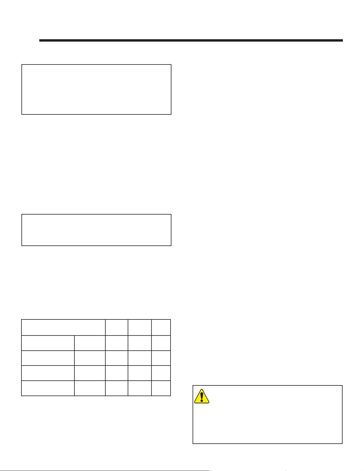
B. Good Faith Wall Surface
FIREPL ACE
OPENI NG
132°F
135°F
147°F
12 in.
6 in.
TOP EDGE OF THE OPENI NG
APPLIA NCE FRONT
Figure 2.1 Good Faith Wall Surface Temperatures Above Appliance
If installing a television (TV) above the appliance, see
Section 3 of the appliance Owner’s Manual.
NOTICE: Temperatures listed above are taken with a
temperature measuring probe as prescribed by the test
standard used for appliance certication. Temperatures
on walls or mantels taken with an infrared thermometer
may yield increased temperatures of up to 30 degrees or
more depending on the thermometer settings and material
characteristics being measured. Use appropriate nishing
materials that are able to withstand these conditions. For
additional nishing guidelines, see Section 10.
TO CEILI NG
127°F
123°F
30 in.
24 in.
18 in.
MEASU REMENTS FROM
Improper installation, adjustment, alteration, service or
maintenance can cause injury or property damage. For
assistance or additional information, consult a qualied
service technician, service agency or your dealer.
6
Heatilator • CNXT4236IFT, CNXT4842IFT Installation Manual • 2515-980 Rev. M • 3/21
C. Tools and Supplies Needed
Before beginning the installation be sure that the following
tools and building supplies are available.
Tape measure Framing material
Pliers Hammer
Phillips screwdriver Manometer
Gloves Framing square
Voltmeter Electric drill and bits (1/4 in.)
Plumb line Safety glasses
Level Reciprocating saw
Flat blade screwdriver
Non-corrosive leak check solution
1/2 - 3/4 in. length, #6 or #8 Self-drilling screws
Caulking material (300 ºF minimum continuous exposure
rating)
One 1/4 in. female connection (for optional fan).

D. Inspect Appliance and Components
• Carefully remove the appliance and components from
the packaging.
• The vent system components and decorative doors and
fronts may be shipped in separate packages.
• If packaged separately, the log set and appliance grate
must be installed.
• Report to your dealer any parts damaged in shipment,
particularly the condition of the glass.
• This product is factory-equipped with an IntelliFire® Touch
remote control, which was paired to the appliance at the
factory. This specic remote control needs to remain with
the contents of the manual bag. Do not install batteries
in the remote control until performing the nal appliance
setup and checklist.
• Read all of the instructions before starting the installation. Follow these instructions carefully during the
installation to ensure maximum safety and benet.
WARNING! Risk of Fire or Explosion! Damaged parts
could impair safe operation. DO NOT install damaged, incomplete or substitute components. Keep appliance dry.
Hearth & Home Technologies disclaims any responsibility for,
and the warranty will be voided by, the following actions:
• Installation and use of any damaged appliance or vent
system component.
• Modication of the appliance or vent system.
• Installation other than as instructed by Hearth & Home
Technologies.
• Improper positioning of the gas logs or the glass assembly.
• Installation and/or use of any component part not approved
by Hearth & Home Technologies.
Any such action may cause a re hazard.
WARNING! Risk of Fire, Explosion or Electric Shock!
DO NOT use this appliance if any part has been under
water. Call a qualied service technician to inspect the
appliance and to replace any part of the control system
and/or gas control which has been under water.
Heatilator • CNXT4236IFT, CNXT4842IFT Installation Manual • 2515-980 Rev. M • 3/21
7
3 3
Framing and Clearances
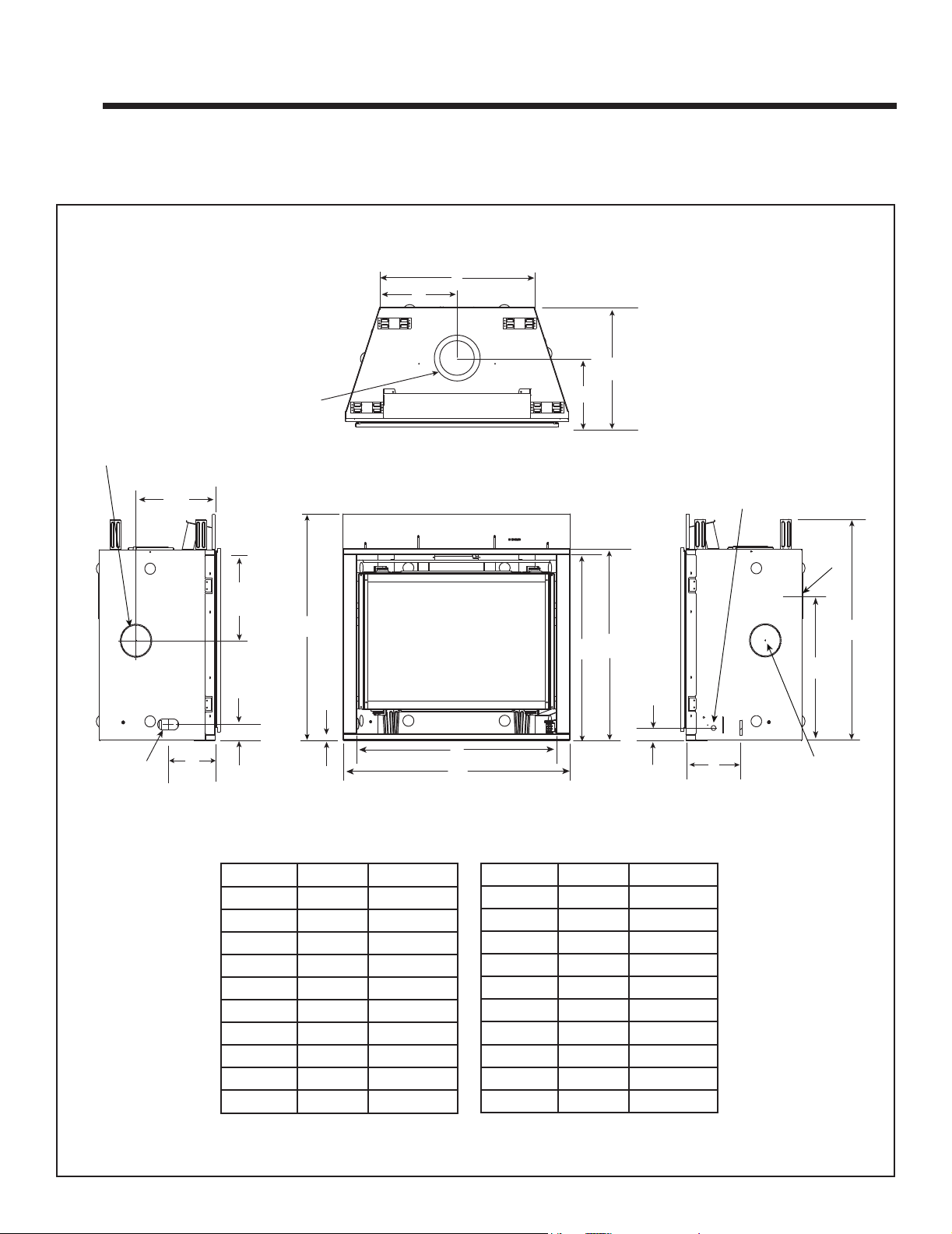
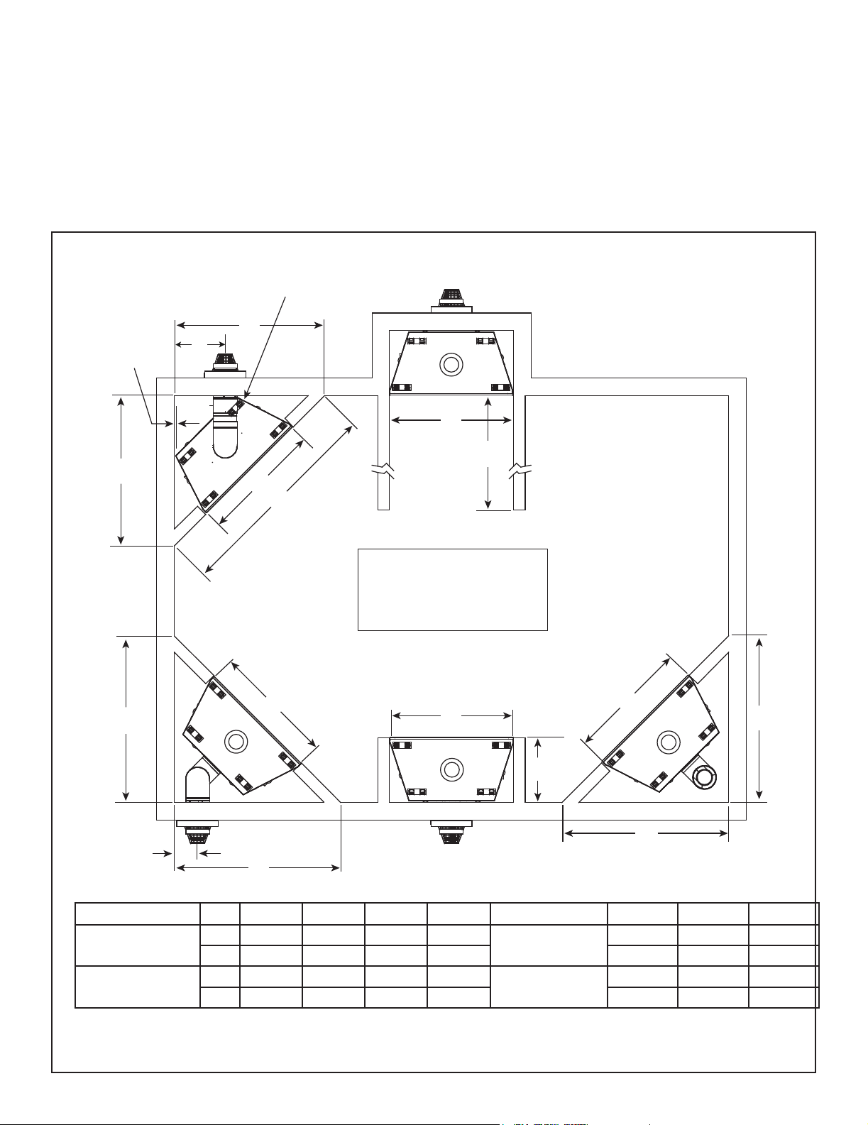
A. Appliance/Decorative Front Dimension Diagrams
Dimensions are actual appliance dimensions. Use for reference only. For framing dimensions and clearances refer to Section 5.
L
M
J
Ø
N
K
HEAT MANAGEMENT SYSTEMS ACCESS
(LEFT & RIGHT SIDES)
S
T
R
O
GAS LINE
ACCESS
LEFT SIDE RIGHT SIDE
P
Q
Location Inches Millimeters
A 41 1041
B 36-1/8 918
C 33-1/2 851
D 34-5/8 879
E 2-1/4 57
F 9-11/16 246
G 26-7/8 683
H 6 dia 152
I 39-7/8 1013
J 21 533
TOP VIEW
B
A
FRONT VIEW
D
C
E
Location Inches Millimeters
K 11-11/16 297
L 28-1/2 724
M 14-1/4 362
N 8-1/2 216
O 2-7/8 73
P 8-1/2 216
Q 1 25
R 40-7/8 1038
S 14-3/16 360
T 15-3/8 391
ELECTRICAL
ACCESS
F
Ø
N
(C)
L
I
G
Ø
H
Figure 3.1 Appliance Dimensions - CNXT4236IFT Models
8
Heatilator • CNXT4236IFT, CNXT4842IFT Installation Manual • 2515-980 Rev. M • 3/21
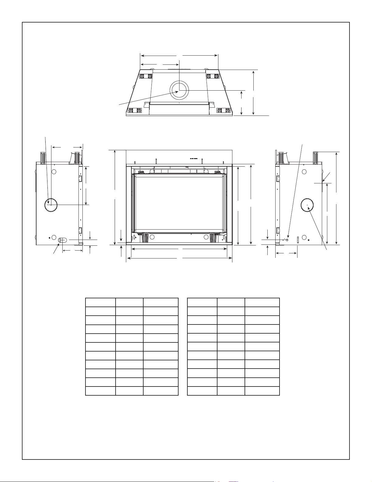
L
M
J
Ø
N
K
HEAT MANAGEMENT
ACCESS (LEFT & RIGHT SIDES)
S
T
O
GAS LINE
ACCESS
LEFT SIDE
P
Location Inches Millimeters
R
Q
A 48 1219
B 43-1/8 1096
C 35-1/2 902
D 36-5/8 930
E 2-3/8 60
F 9-15/16 252
G 28-7/8 734
H 6 152
I 41-7/8 1064
J 21 533
TOP VIEW
B
A
FRONT VIEW
D
C
E
Location Inches Millimeters
K 11-11/16 297
L 35-1/2 901
M 17-3/4 451
N 8-1/2 216
O 2-7/8 73
P 8-1/2 216
Q 1 25
R 42-7/8 1089
S 14-1/16 357
T 17-1/16 433
ELECTRICAL
ACCESS
F
RIGHT VIEW
Ø
N
(C)
L
I
G
H
Ø
Figure 3.2 Appliance Dimensions - CNXT4842IFT Models
Heatilator • CNXT4236IFT, CNXT4842IFT Installation Manual • 2515-980 Rev. M • 3/21
9
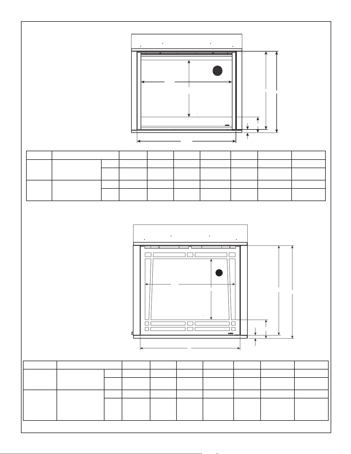
SIMON DECORATIVE FRONTS
(INSIDE FIT)
Refer to Section 10 for nishing details.
A
B
F
G
E
A B C D E F G
SIM-36C
SIM-42C
CNXT4236IFTT
CNXT4236IFTH
CNXT4236IFTSG
CNXT4842IFTT
CNXT4842IFTH
CNXT4842IFTSG
in. 32-7/16 22-1/16 35-13/16 1-7/16 7-1/16 32-1/16 33-1/2
mm 824 560 910 37 179 814 851
in. 39-7/16 24 42-13/16 1-7/16 7-1/16 33-15/16 35-3/8
mm 1002 610 1087 37 179 862 899
CRAFTSMAN DECORATIVE FRONTS
(INSIDE FIT)
Refer to Section 10 for nishing details.
C
A
B
D
F
G
A B C D E F G
CNXT4236IFTT
CRAFT-36C
CRAFT-42C
Figure 3.3 Decorative Front dimensions - Simon and Craftsman
10
CNXT4236IFTH
CNXT4236IFTSG
CNXT4842IFTT
CNXT4842IFTH
CNXT4842IFTSG
Heatilator • CNXT4236IFT, CNXT4842IFT Installation Manual • 2515-980 Rev. M • 3/21
in. 32-3/8 21-7/8 35-15/16 1-1/4 6-3/4 32-1/4 33-1/2
mm 822 556 913 32 172 819 851
in. 39-5/16 23-13/16 42-13/16 1-1/4 6-3/4 34-1/8 35-3/8
mm 999 605 1087 32 172 867 905
E
C D
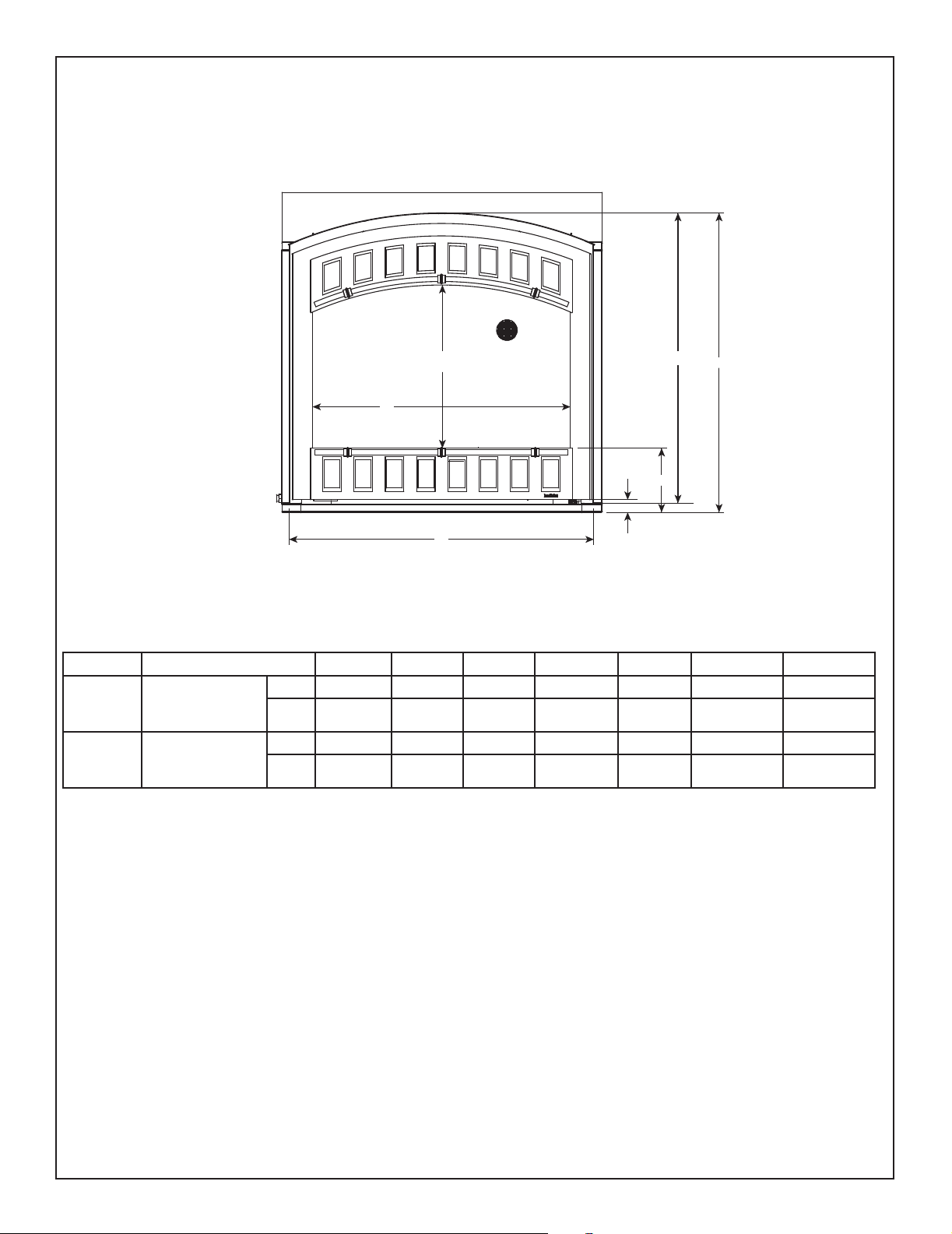
CONTOUR DECORATIVE FRONTS
(INSIDE OR OVERLAP FIT)
Refer to Section 10 for nishing details.
CON-36C
CON-42C
CNXT4236IFTT
CNXT4236IFTH
CNXT4236IFTSG
CNXT4842IFTT
CNXT4842IFTH
CNXT4842IFTSG
B
A
C D
F
G
E
A B C D E F G
in. 33 20-7/8 39 1-3/8 8 37-1/4 38-1/4
mm 838 530 991 35 203 946 972
in. 40 22-3/4 46 1-3/8 8 39 40
mm 1016 578 1168 35 203 991 1016
Figure 3.4 Decorative Front dimensions - Contour
Heatilator • CNXT4236IFT, CNXT4842IFT Installation Manual • 2515-980 Rev. M • 3/21
11
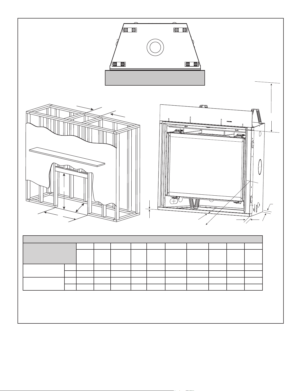
B. Clearances to Combustibles
When selecting a location for the appliance it is important
to consider the required clearances to walls (see Figure
3.5).
WARNING! Risk of Fire or Burns! Provide adequate
clearance around air openings and for service access.
Due to high temperatures, the appliance should be lo-
cated out of trac and away from furniture and draperies.
NOTE: THE REAR STANDOFF MAY NEED
TO BE REMOVED WHEN VENTING AT 45º
A
1/2 IN .
G
INSTALLATION
A
B
C
TOP VENT
ONE 90º ELBOW
NOTICE: Illustrations reect typical installations and are
FOR DESIGN PURPOSES ONLY. Illustrations/diagrams
are not drawn to scale. Actual installation may vary due to
individual design preference.
B
ALCOVE
E
D
H
CNXT4236 Series
CNXT4842 Series
Refer to Section 10.B for mantel and wall
projection information.
Consider the mantel or cabinet system to be
installed and comply with the necessary
requirements for elevated hearth. Refer to
instructions included with cabinet system.
REAR VENT,
HORIZONTAL TERMINATION
TWO ELBOWS
B
REAR VENT
NO ELBOWS
B
REAR VENT
ONE ELBOW
B
D
F
D
D
A B C D E F G H
in. 51 42 72 56-5/8
mm 1295 1067 1829 1438 559 451 203
in. 55-7/8 49 79 61-1/2
mm 1419 1245 2007 1562 559 502 254
See Section 10.B.
Mantel Projections
See Section 10.B.
Mantel Projections
22 17-3/4 8
22 19-3/4 10
Figure 3.5 Appliance Locations
12
Heatilator • CNXT4236IFT, CNXT4842IFT Installation Manual • 2515-980 Rev. M • 3/21
COMBUSTIBLE FLOORING MAY BE INSTALLED
NEXT TO THE FRONT OF THE APPLIANCE.
A
E
B
F
C
H
D
* MINIMUM FRAMING DIMENSIONS
A B C** D E F G H I J
Models
CNXT4236 Series
CNXT4842 Series
Rough
Opening
(Width)
in. 10 40-1/8 22 42 32 0 0 1/2 1/2 36
mm 254 1019 559 1067 813 0 0 13 13 914
in. 10 42-1/8 22 49 32 0 0 1/2 1/2 36
mm 254 1070 559 1245 813 0 0 13 13 914
* Adjust framing dimensions for interior sheathing (such as sheetrock)
C** Add 12 inches for rear venting with one 90º elbow.
Figure 3.6 Clearances to Combustibles
Rough
Opening
(Height)
Rough
Opening
(Depth)
Rough
Opening
(Width)
Clearance
to Ceiling
Combustible
Floor
G
J
Combustible
Flooring
Behind
Appliance
I
Sides of
Appliance
Front of
Appliance
Heatilator • CNXT4236IFT, CNXT4842IFT Installation Manual • 2515-980 Rev. M • 3/21
13

C. Constructing the Appliance Chase
A chase is a vertical box-like structure built to enclose the
gas appliance and/or its vent system. In cooler climates
the vent should be enclosed inside the chase.
NOTICE: Treatment of ceiling restops and wall shield
restops and construction of the chase may vary with the
type of building. These instructions are not substitutes
for the requirements of local building codes. Therefore,
you MUST check local building codes to determine the
requirements to these steps.
NOTICE: Where required by code, install only sprinkler
heads with a sprinkler activation temperature classied
as Extra High.
• Sprinklers inside of chase: Keep sprinkler head away
from vent and chimney.
• Heat Management applications: Maintain 36 inches of
clearance to openings from which heat is discharged
such as heat zone registers, etc. Refer to Section 6.B
for Heat Management options allowed for this appliance.
Chases should be constructed and insulated in the same
manner as the thermal envelope of the home based on
the code requirements for that climate zone to prevent air
leakage and draft problems. The chase is an extension of
the building thermal envelope.
To further prevent drafts and air leakage, the wall shield
and ceiling restops should be caulked with caulk with
a minimum of 300 ºF continuous exposure rating to
seal gaps. Gas line holes and other openings should
be caulked with caulk with a minimum of 300 ºF continuous exposure rating or stued with unfaced insulation. If the
appliance is being installed on a cement surface, a layer of
plywood may be placed underneath to prevent conducting
cold up into the room.
NOTICE: Install appliance on hard metal or wood surfaces
extending full width and depth. DO NOT install directly
on carpeting, vinyl, tile or any combustible material other
than wood.
WARNING! Risk of Fire! Maintain specied air space
clearances to appliance and vent pipe:
• Insulation and other materials must be secured to prevent
accidental contact.
• The chase must be properly blocked to prevent blown
insulation or other combustibles from entering and
making contact with replace or chimney.
• Failure to maintain airspace may cause overheating and
a re.
14
Heatilator • CNXT4236IFT, CNXT4842IFT Installation Manual • 2515-980 Rev. M • 3/21
4 4
A B
Termination Location and Vent Information
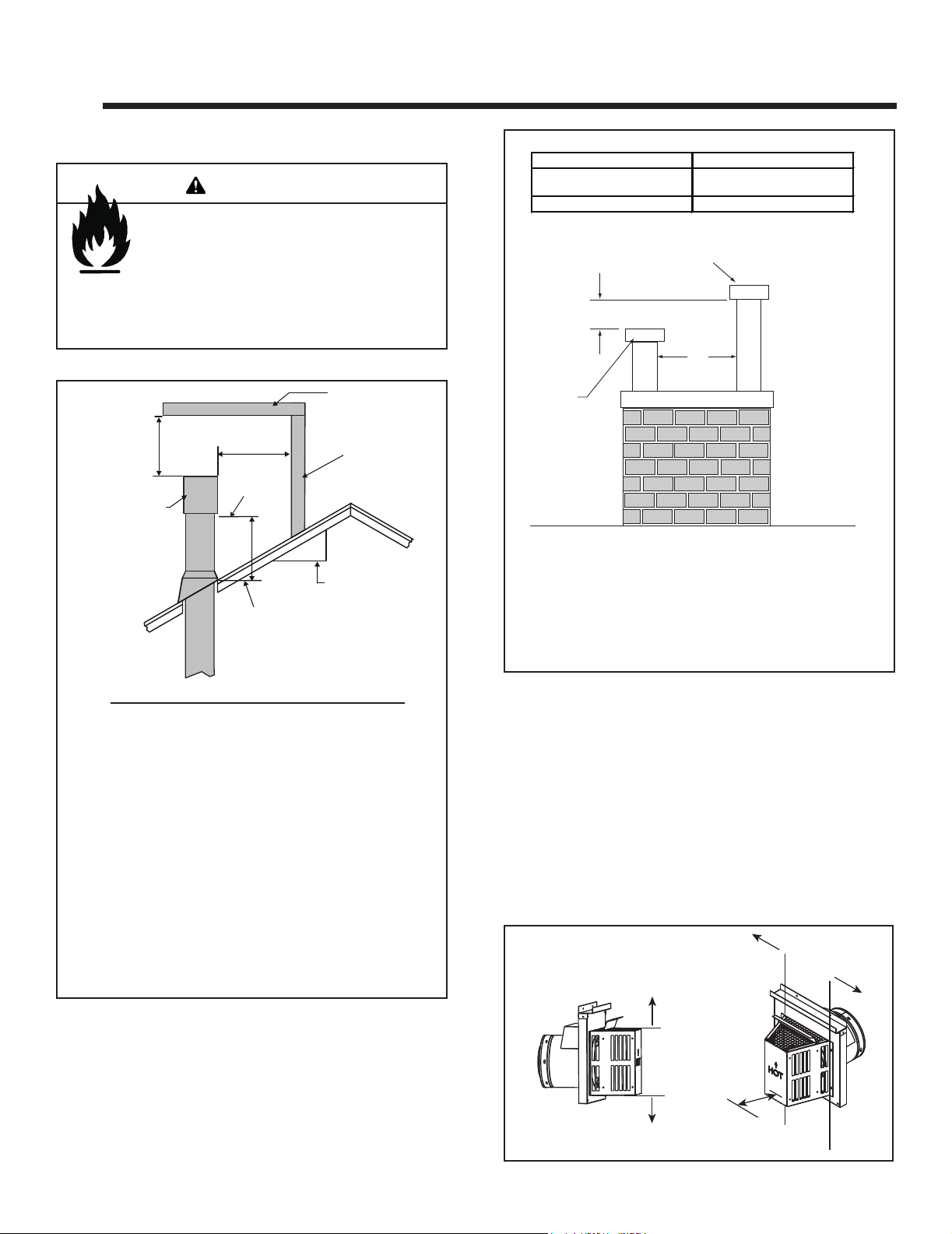
A. Vent Termination Minimum Clearances
Fire Risk.
Maintain vent clearance to combustibles as
specied.
• DO NOT pack air space with insulation or other
Failure to keep insulation or other materials away
from vent pipe could cause overheating and re.
2 FT.
MIN.
GAS DIRECT VENT
TERMINATION CAP
materials.
WARNING
HORIZONTAL
OVERHANG
20 INCHES MIN.
LOWEST
DISCHARGE
OPENING
H (MIN.) - MINIMUM HEIGHT FROM ROOF
TO LOWEST DISCHARGE OPENING
X
12
ROOF PITCH
IS X/ 12
VERTICAL
WALL
6 in. (minimum) up to 20 in.
152 mm/508 mm
20 in. and over 0 in. minimum
18 in. minimum
457 mm
Gas, Wood or Fuel Oil
Termination Cap
B
A *
Gas
Termination
Cap **
If using decorative cap cover(s), this distance may need to be
*
increased. Refer to the installation instructions supplied with the
decorative cap cover.
In a staggered installation with both gas and wood or fuel oil
**
terminations, the wood or fuel oil termination cap must be
higher than the gas termination cap.
Roof Pitch H (Min.) Ft.
Flat to 6/12...........................................................1.0*
Over 6/12 to 7/12 .................................................1.25*
Over 7/12 to 8/12 .................................................1.5*
Over 8/12 to 9/12 .................................................2.0*
Over 9/12 to 10/12 ...............................................2.5*
Over 10/12 to 11/12 .............................................3.25
Over 11/12 to 12/12 .............................................4.0
Over 12/12 to 14/12 .............................................5.0
Over 14/12 to 16/12 .............................................6.0
Over 16/12 to 18/12 .............................................7.0
Over 18/12 to 20/12 .............................................7.5
Over 20/12 to 21/12 .............................................8.0
* H minimum may vary depending on regional snowfall.
Refer to local codes.
Figure 4.1 Minimum Height From Roof to Lowest Discharge
Opening
Figure 4.2 Staggered Termination Caps
CAUTION! Risk of Burns! Termination caps are HOT,
consider proximity to doors, trac areas or where people
may pass or gather (sidewalk, deck, patio, etc.). Listed
cap shields available. Contact your dealer.
• Local codes or regulations may require different
clearances.
• Hearth & Home Technologies assumes no responsibility
for the improper performance of the appliance when the
venting system does not meet these requirements.
• Vinyl protection kits are suggested for use with vinyl siding.
• Measure horizontal and vertical termination cap clearances
as noted in Figure 4.3.
H=Measure Horizontal Distances from H
V=Measure Vertical Distances from V
V
CLEARANCE
V
= 6 IN.
H
H
Heatilator • CNXT4236IFT, CNXT4842IFT Installation Manual • 2515-980 Rev. M • 3/21
Figure 4.3
15
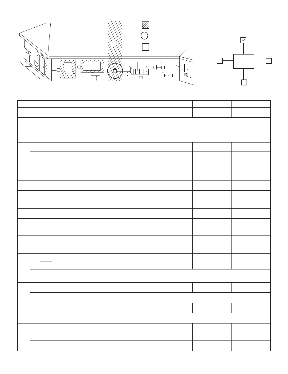
B. Vent Terminal Clearances
= AREA WHERE TERMINAL IS NOT PERMITTED
X
= AIR SUPPLY INLET
C
V
B
J
V
U.S.A. Installations: In accordance with the current ANSI Z223.1/NFPA 54, National Fuel Gas Code.
Canadian Installations: In accordance with the current CSA B149.1, Natural Gas and Propane Installation Code.
B
D
V
V
V
A
F
B
G
M
V
= VENT TERMINAL
H or i
V
X
V
V
V
H
H
E
V
V
A
U.S.A. CANADA
A Clearance above grade,veranda, porch, deck, or balcony 12 in. (305 mm) 12 in. (305 mm)
Clearance to window or door that may be opened, or to permanently closed window
B
U.S.A.: = 9 in. min. (229 mm min.) CANADA: = 12 in. min. ( 305 mm min.)
clearance below unventilated sot 18 in. (457 mm) 18 in. (457 mm)
K
V
L
Electrical
Service
C
V
K
V
C
clearance below ventilated sot 18 in. (457 mm) 18 in. (457 mm)
clearance below any vinyl sots and electrical service 30 in. (762 mm) 30 in. (762 mm)
D clearance to outside corner 6 in. (152 mm) 6 in. (152 mm)
E clearance to inside corner 6 in. (152 mm) 6 in. (152 mm)
not to be installed above a gas meter/regulator assembly within 3 feet horizontally from
F
the center-line of the regulator
3 ft (914 mm) 3 ft (914 mm)
G clearance to gas service regulator vent outlet 3 ft (914 mm) 3 ft (914 mm)
clearance to non-mechanical air supply inlet to building or the combustion air inlet to
H
any other appliance termination (mechanical or non-mechanical)
9 in. min.
(229 mm min.)
12 in. min.
(305 mm min.)
clearance to a mechanical (powered) air supply inlet
I
***(All mechanical air intakes within 10 feet of a horizontal termination cap must be
3 ft (914 mm)*** 6 ft (1.8 m)
a minimum of 3 feet below termination.)
On public property: clearance above paved sidewalk or a paved driveway.
7 ft (2.1 m) 7 ft (2.1 m)**
J
**(A vent shall not terminate directly above a sidewalk or paved driveway which is located between two single family dwellings
and serves both dwellings.)
clearance from sides of electrical service 6 in. (152 mm) 6 in. (152 mm)
K
Location of the vent termination must not interfere with access to the electrical service.
clearance above electrical service 12 in. (305 mm) 12 in. (305 mm)
L
Location of the vent termination must not interfere with access to the electrical service.
clearance under veranda, porch, deck, balcony or overhang
*(Permitted only if veranda, porch, deck, or balcony is fully open on a minimum of
M
two sides beneath the oor.)
vinyl or composite overhang 42 in. (1067 mm) 42 in. (1067 mm)
Figure 4.4 Minimum Clearances for Termination
16
Heatilator • CNXT4236IFT, CNXT4842IFT Installation Manual • 2515-980 Rev. M • 3/21
18 in. (457 mm) 12 in. (305 mm)*

C. Approved Pipe
This appliance is approved for use with Hearth & Home
Technologies DVP or SLP venting systems. Refer to Section 12.A for vent component information and dimensions.
Only use listed decorative termination caps/shrouds with
Hearth & Home Technologies approved venting systems.
DO NOT mix pipe, ttings or joining methods from dierent manufacturers.
The pipe is tested to be run inside an enclosed wall.
There is no requirement for inspection openings at each
joint within the wall.
WARNING! Risk of Fire or Asphyxiation. This appliance requires a separate vent. DO NOT vent to a pipe
serving a separate solid fuel burning appliance.
Heatilator • CNXT4236IFT, CNXT4842IFT Installation Manual • 2515-980 Rev. M • 3/21
17
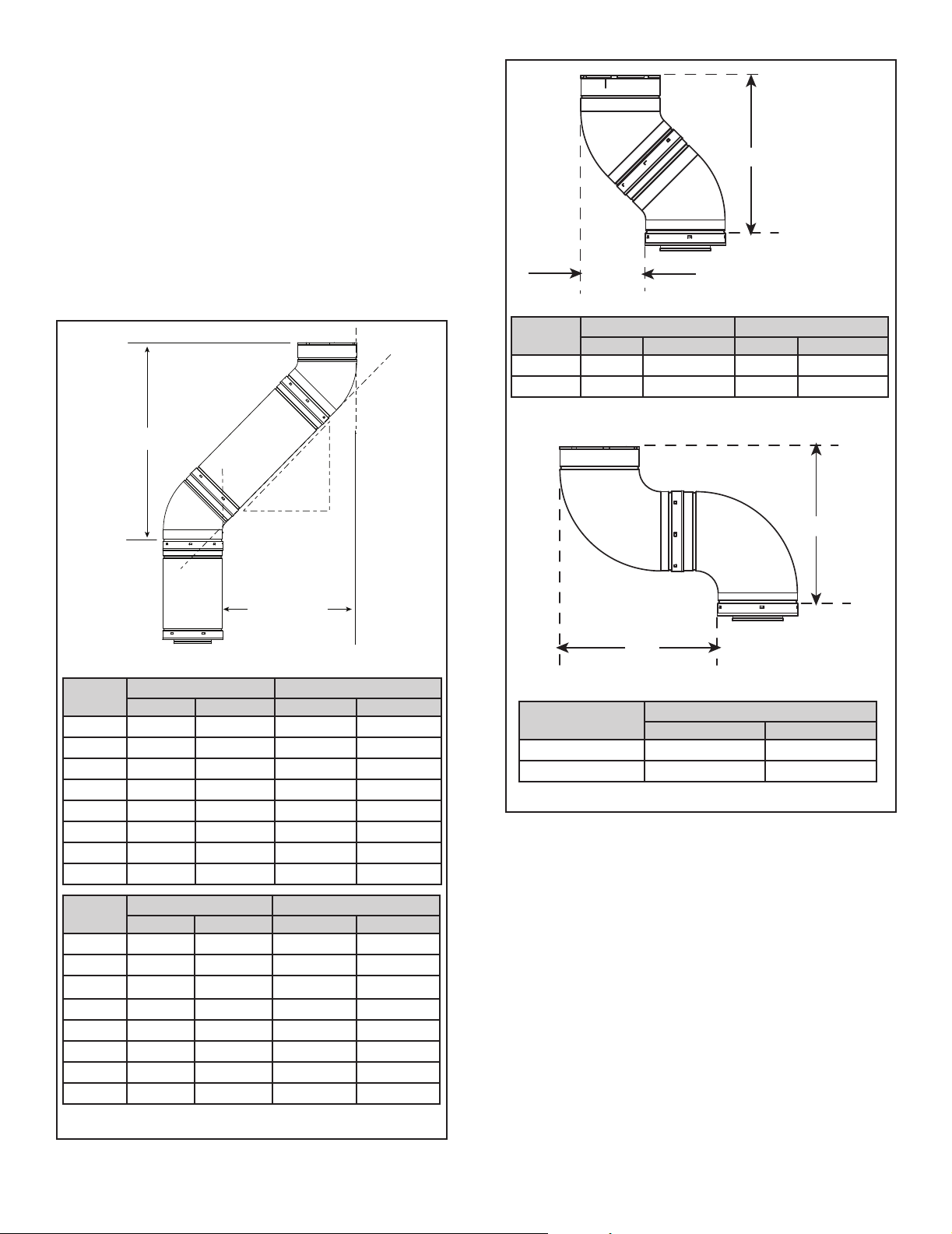
D. Use of Elbows
Diagonal runs have both vertical and horizontal vent aspects when calculating the eects. Use the rise for the
vertical aspect and the run for the horizontal aspect. See
Figure 4.5.
Two 45º elbows may be used in place of one 90º elbow.
On 45º runs, one foot of diagonal is equal to 8-1/2 in. (216
mm) horizontal run and 8-1/2 in. (216 mm) vertical run. A
length of straight pipe is allowed between two 45º elbows.
See Figure 4.5.
Figure 4.6 shows the vertical and horizontal osets for
DVP or SLP elbows.
Y
X
VERTICAL
RISE
SLP
Pipe
EFFECTIVE
LENGTH
RUN
HORIZONTAL
Eective Length Rise/Run
Inches Millimeters Inches Millimeters
SLP4 4 102 2-3/4 70
SLP6 6 152 4-1/4 108
SLP12 12 305 8-1/2 216
SLP24 24 610 17 432
SLP36 36 914 25-1/2 648
SLP48 48 1219 34 864
SLP6A 3 to 6 76 to 152
SLP12A 3 to 12 76 to 305
2-1/8-4-1/4 54-108
2-1/8-8-1/2 54-216
Vent
Type
Inches Millimeters Inches Millimeters
X Y
DVP 6-5/8 168 16-1/2 419
SLP 5-1/4 133 11-3/8 289
X
X
Vent Type
Inches Millimeters
DVP 16-1/4 413
SLP 11-1/4 286
Figure 4.6 Vertical and Horizontal Oset for DVP and SLP Elbows
X
DVP
Pipe
Eective Length Rise/Run
Inches Millimeters Inches Millimeters
DVP4 4 102 2-3/4 70
DVP6 6 152 4-1/4 108
DVP12 12 305 8-1/2 216
DVP24 24 610 17 432
DVP36 36 914 25-1/2 648
DVP48 48 1219 34 864
DVP6A 3 to 6 76 to 152
DVP12A 3 to 12 76 to 305
Figure 4.5
18
Heatilator • CNXT4236IFT, CNXT4842IFT Installation Manual • 2515-980 Rev. M • 3/21
2-1/8-4-1/4 54-108
2-1/8-8-1/2 54-216
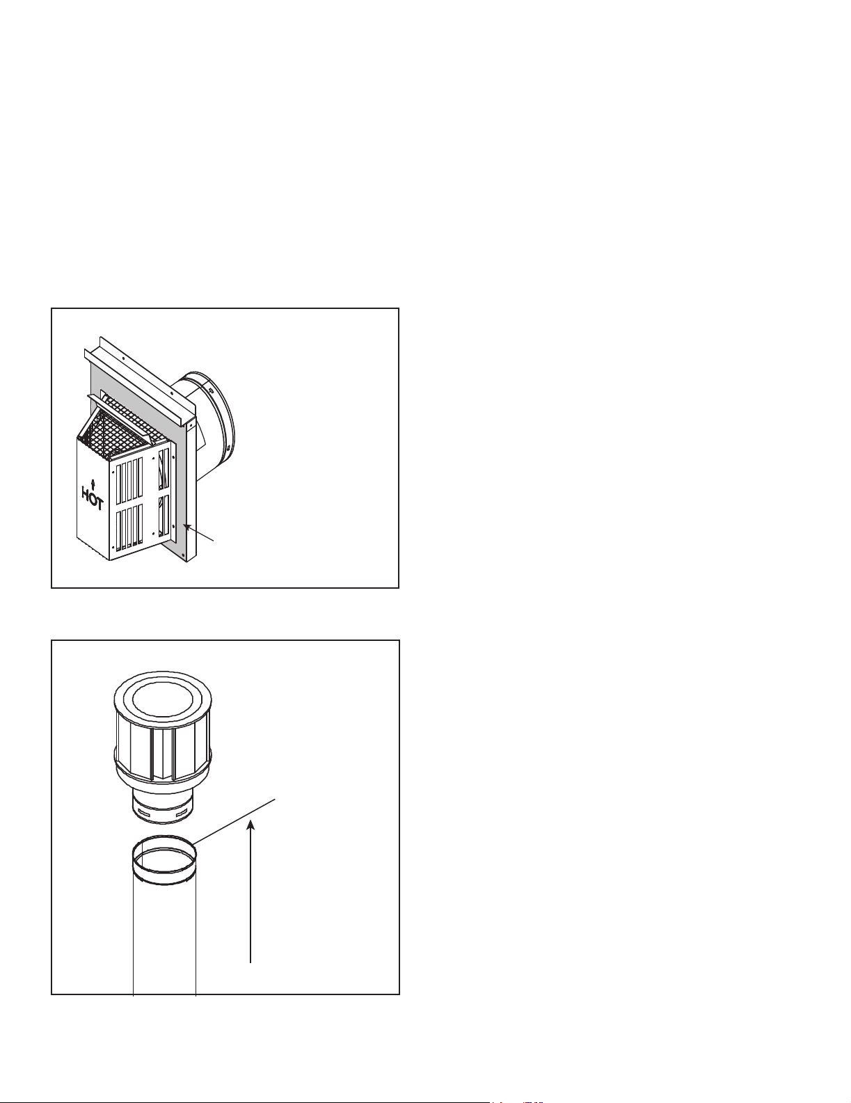
E. Measuring Standards
Vertical and horizontal measurements listed in the vent
diagrams were made using the following standards:
• Pipe measurements are shown using the eective length
of pipe. See Section 12.A (Figure 12.1 for DVP, Figure
12.6 for SLP) for information on eective length of pipe
components.
• Horizontal terminations are measured to the outside
mounting surface (ange of termination cap) (see Figure
4.7).
• Vertical terminations are measured to top of last section
of pipe. See Figure 4.8.
• Horizontal pipe installed level with no rise.
MEASURE TO SHADED SURFACE
(OUTSIDE MOUNTING SURFACE)
Figure 4.7 Measure to Outside Mounting Surface
Figure 4.8 Measure to Top of Last Section of Pipe
Heatilator • CNXT4236IFT, CNXT4842IFT Installation Manual • 2515-980 Rev. M • 3/21
19
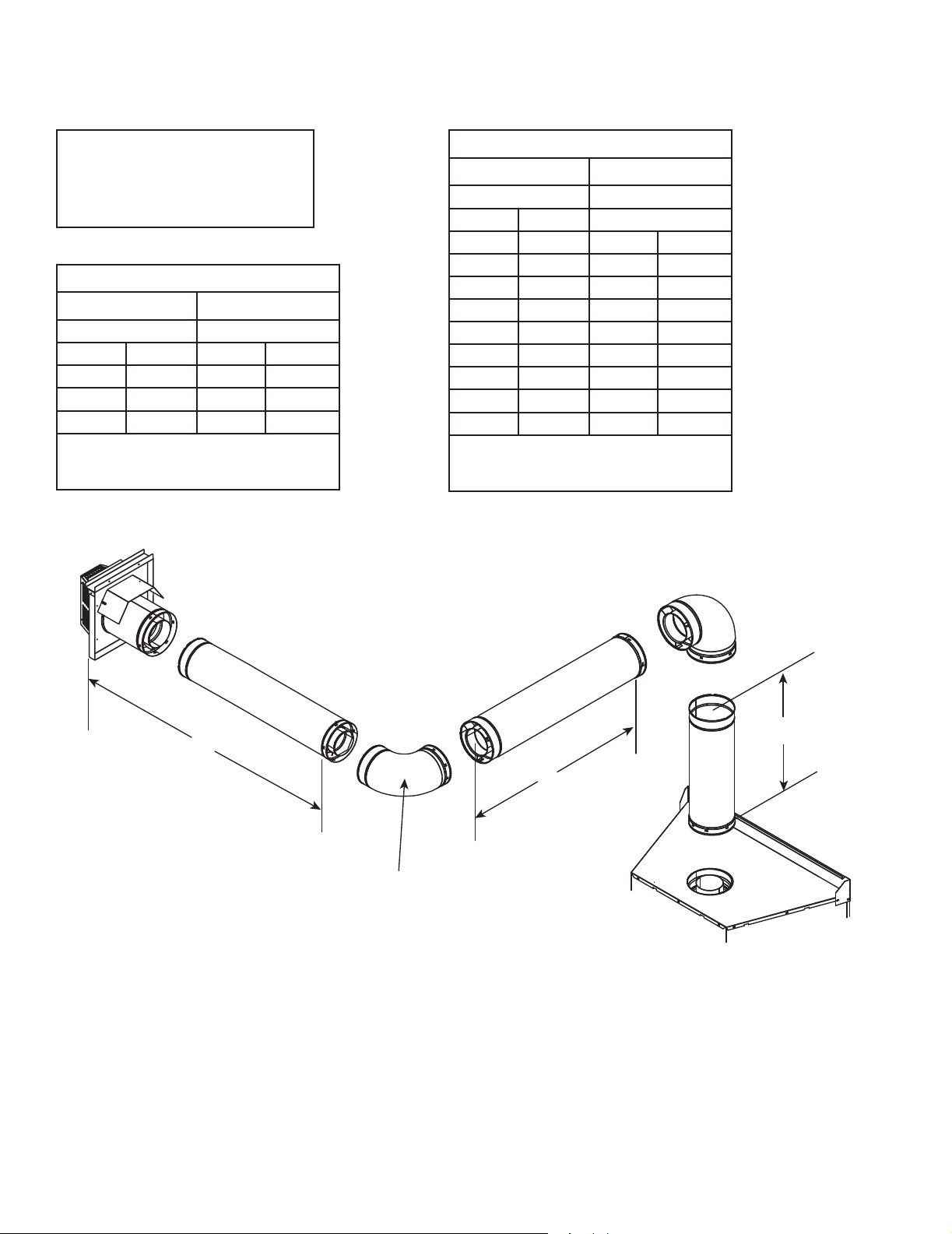
F. Vent Diagrams
General Rules:
• SUBTRACT 3 ft. from the total H measurement for each
90º elbow installed horizontally.
• SUBTRACT 1-1/2 ft. from the total H measurement for
each 45º elbow installed horizontally.
• A maximum of three 90º elbows (or six 45º elbows) may
be used in any vent conguration. Some elbows may be
installed horizontally. For an example, see Figure 4.20.
• Elbows may be placed back to back anywhere in the
system.
• Any 90º elbow may be replaced with two back to back
45º elbows.
• When penetrating a combustible wall, a wall shield
restop must be installed.
• When penetrating a combustible ceiling, a ceiling restop
must be installed.
• Horizontal runs of vent do not require vertical rise;
horizontal runs may be level.
• Horizontal termination cap should have a 1/4 inch
downward slant to allow any moisture in cap to be
released. See Figure 4.9.
1/4 in. max.
Figure 4.9
20
(6 mm)
Heatilator • CNXT4236IFT, CNXT4842IFT Installation Manual • 2515-980 Rev. M • 3/21
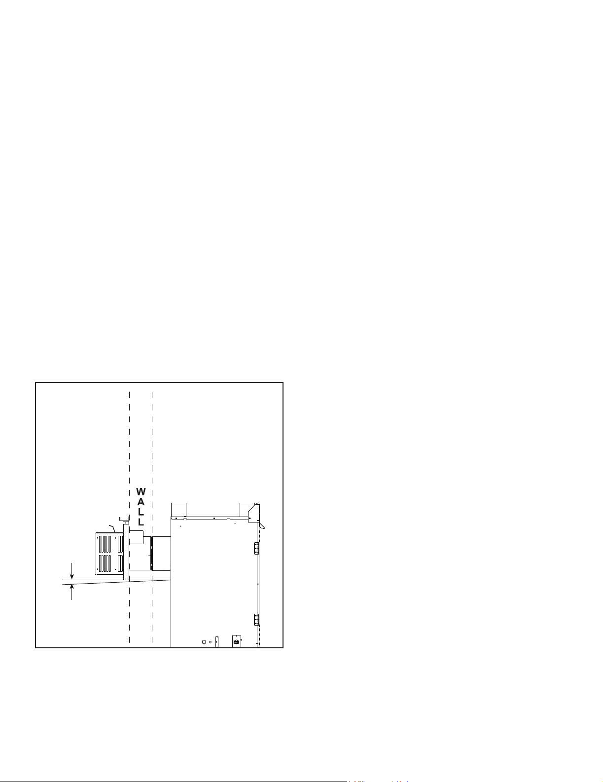
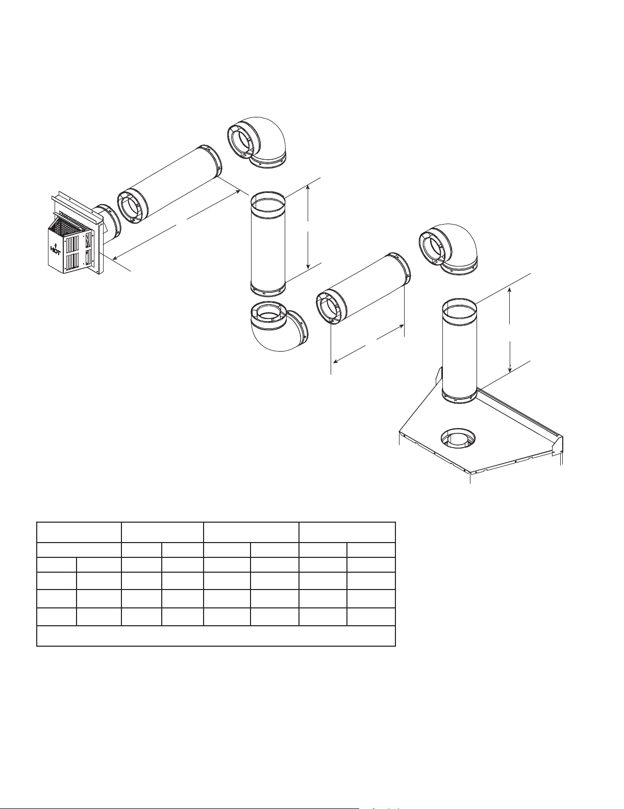
Top Vent - Horizontal Termination
H
1
V
1
ELBOW HEAT SHIELD
(Required when V
1
= 2 ft. or less)
Note: The CNXT series replaces can adapt to SLP series vent pipe,
if desired.
When venting o the top of the unit, use a DVP-2SL adapter and a
minimum 48 inch vertical section of SLP series vent pipe.
A DVP-SLP24 adapter may also be used with a 24 inch vertical
section of SLP series vent pipe.
After the 48 inch vertical section, the venting table rules must be
followed. The rst 48 inch vertical section is NOT counted as part of
the vertical components in the table. It is still counted as part of the
overall maximum run. All venting table rules for the vent run must
still be followed.
Example: DVP pipe 3 ft. min. vertical = 11 ft. max. horizontal
SLP pipe 7 ft. min. vertical = 11 ft. max. horizontal
One Elbow
WARNING! Risk of Fire! Elbow heat shield required
when V1 = 2 ft. or less. Clearances to combustibles
must be maintained. See Section 5.A.
WARNING
Fire Risk. Explosion Risk.
Do NOT pack insulation or other combustibles
between ceiling restops.
• ALWAYS maintain specied clearances around
venting and restop systems.
• Install wall shield and ceiling restops as specied.
Failure to keep insulation or other material away
from vent pipe may cause re.
WARNING
Fire Risk.
• When using DVP-HRC-SS and DVP-HRC-ZCSS termination caps on top vented replaces, a
6 inch minimum vertical vent section is required
before installing rst elbow.
Note: For corner installations: A 6 in.
(152 mm) section of straight pipe may
need to be attached to the appliance
before a 90º elbow, to allow the vent
pipe to clear the top standos.
CNXT4236 Series
V1 Minimum H1 Maximum
Elbow only 2 ft. 610 mm
1/2 ft. 152 mm 6 ft. 1.8 m
1 ft. 305 mm 11 ft. 3.4 m
1-1/2 ft. 457 mm 18 ft. 5.5 m
2 ft. 610 mm 25 ft. 7.6 m
V1 + H1 = 40 ft. (12.2 m) Maximum
H1 = 25 ft. (7.6 m) Maximum
CNXT4842 Series
V1 Minimum H1 Maximum
Elbow only 2 ft. 610 mm
1/2 ft. 152 mm 2 ft. 610 mm
1 ft. 305 mm 4 ft. 1.2 m
1-1/2 ft. 457 mm 6 ft. 1.8 m
2 ft. 610 mm 8 ft. 2.4 m
2-1/2 ft. 762 mm 8 ft. 2.4 m
3 ft. 914 mm 12 ft. 3.7 m
4 ft. 1.2 m 20 ft. 6.1 m
6 ft. 1.9 m 25 ft. 7.6 m
V1 + H1 = 40 ft. (12.2 m) Maximum
H1 = 25 ft. (7.6 m) Maximum
Figure 4.10
Heatilator • CNXT4236IFT, CNXT4842IFT Installation Manual • 2515-980 Rev. M • 3/21
21
Top Vent - Horizontal Termination - (continued)
Two Elbows
Note: For corner installations: A 6 inch
(152 mm) section of straight pipe may
need to be attached to the appliance
before a 90º elbow, to allow the vent
pipe to clear the top standos.
CNXT4236 Series
V1 Minimum H1 + H2 Maximum
Elbow only Not allowed
1/2 ft. 152 mm 6 ft. 1.8 m
1 ft. 305 mm 11 ft. 3.4 m
1-1/2 ft. 457 mm 18 ft. 5.5 m
2 ft. 610 mm 25 ft. 7.6 m
V1 + H1 + H2 = 40 ft. (12.2 m) Maximum
H1 + H2 = 25 ft. (7.6 m) Maximum
V1 = 1/2 ft. (152 mm) Minimum
CNXT4842 Series
V1 Minimum H1 + H2 Maximum
Elbow only Not allowed
1/2 ft. 152 mm Not allowed
1 ft. 305 mm 2 ft. 610 mm
1-1/2 ft. 457 mm 2 ft. 610 mm
2 ft. 610 mm 4 ft. 1.2 m
2-1/2 ft. 762 mm 4 ft. 1.2 m
3 ft. 914 mm 6 ft. 1.8 m
4 ft. 1.2 m 10 ft. 3.1 m
6 ft. 1.9 m 14 ft. 4.3 m
8 ft. 2.4 m 18 ft. 5.5 m
10 ft. 3.1 m 20 ft. 6.1 m
V1 + H1 + H2 = 40 ft. (12.2 m) Maximum
H1 + H2 = 20 ft. (6.1 m) Maximum
V1 = 1 ft. (305 mm) Minimum
Figure 4.11
H
V
2
H
1
1
INSTALLED
HORIZONTALLY
22
Heatilator • CNXT4236IFT, CNXT4842IFT Installation Manual • 2515-980 Rev. M • 3/21
Top Vent - Horizontal Termination - (continued)
Three Elbows
H
2
V
2
V
H
1
1
V1 Min. H1 Max. V2 Min. H2 Max.
Elbow only 2 ft. 610 mm 0 in. 0 mm 1 ft. 305 mm
6 in. 152 mm 3 ft. 914 mm 6 in. 152 mm 2 ft. 610 mm
1 ft. 305 mm 6 ft. 1.8 m 1 ft. 305 mm 6 ft. 1.8 m
2 ft. 610 mm 11 ft.* 3.4 m* 2 ft. 610 mm 10 ft.* 3.1 m*
3 ft. 914 mm 16 ft. * 4.9 m* 3 ft. 914 mm 14 ft.* 4.3 m*
*H1 + H2 = 20 ft. (6.1 m) Maximum V1 + V2 + H1 + H2 = 40 ft. (12.2 m) Maximum
Figure 4.12
Heatilator • CNXT4236IFT, CNXT4842IFT Installation Manual • 2515-980 Rev. M • 3/21
23
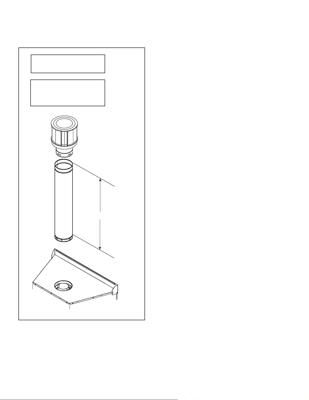
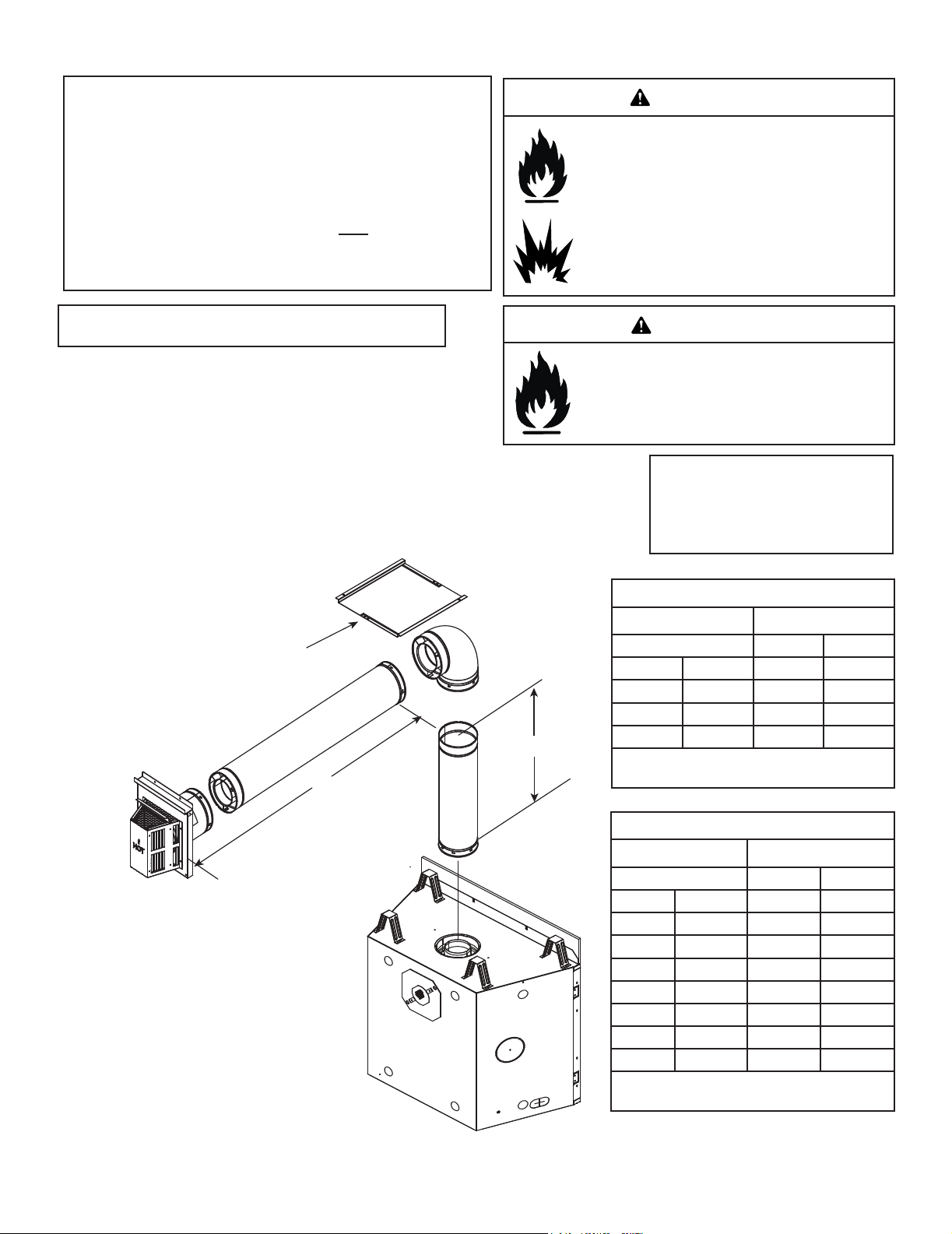
Top Vent - Vertical Termination
No Elbow
V1 = 60 ft. Max. (18.3 m)
V1 = 3 ft. Min. (914 mm)
Note: If installing a vertical vent/
termination o the top of the appliance, the ue restrictor should be
used. See Figure 4.17.
Figure 4.13
V
1
24
Heatilator • CNXT4236IFT, CNXT4842IFT Installation Manual • 2515-980 Rev. M • 3/21
 Loading...