

Heatilator CFL-18NG Log Placement Instructions
LOG PLACEMENT INSTRUCTIONS
Models:
CFL-18NG/LP
CFL-18NG/LP-B
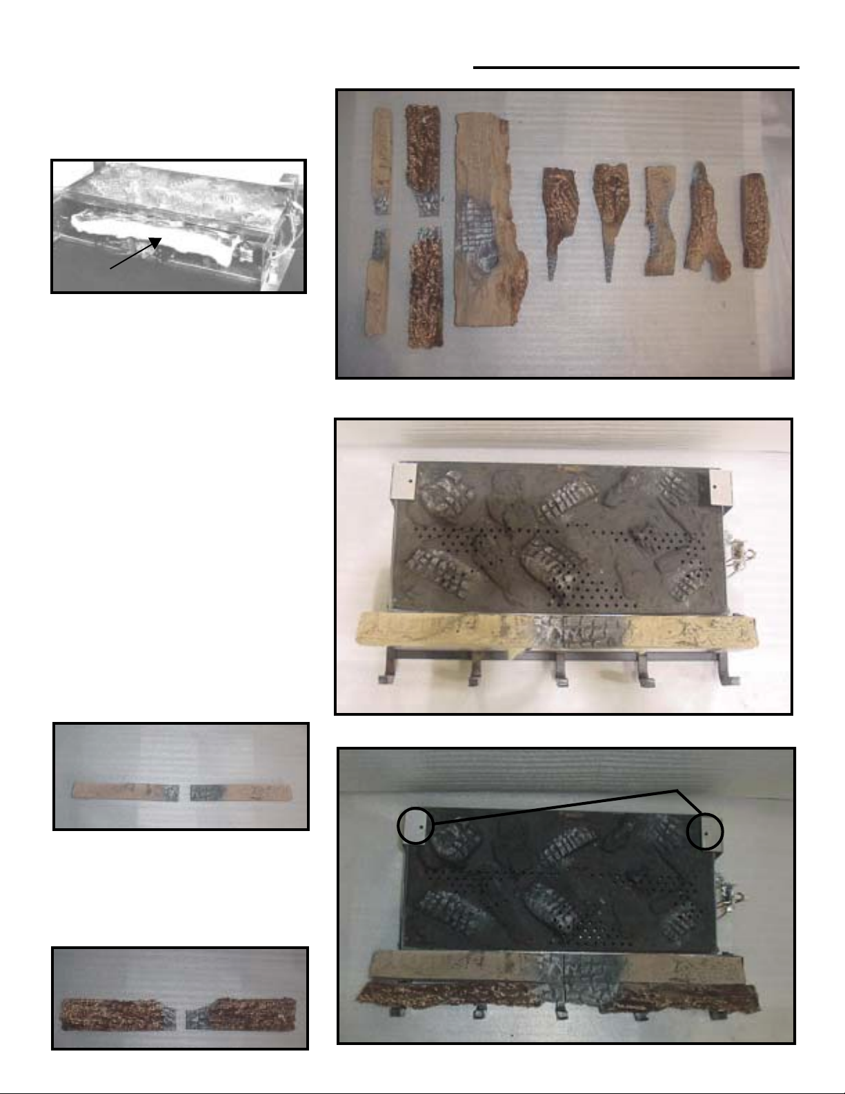
INSULATION
NOTE: An additional piece of INSULATION
is shipped with your log set. If this piece is
missing, DO NOT PROCEED. Call your deal-
er. Following the instructions given below is
very important (Flat spots will guide you
throughout the process). Use the log numbers to identify the logs. Check to make sure
the tabs on the side of burner legs are bent
outward. After setting burner, place insulation provided with log set beneath burner assembly and above valve. Make sure valve is
totally covered. W ARNING: Failure to do so
will cause the unit to malfunction and create
a potential dangerous situation. Set og grate
by resting it down and sliding it toward burner. Make sure right and left grate bars slide
on outside of burner legs between tabs. Place
“dime size” pieces of mineral wool on the
top of the burner, sp aced dimes width apart.
1 3
5 6 7 8 9 10
2 4
LOG #1 & #2: (SRV481-766)
Set logs #1 and 2 in front of the burner. Rest
the bottom two notches over the extended
material of the burner legs. Slide it towards
the burner until it comes in contact with the
burner.
1
LOG #3 & #4: (SRV481-755)
Set logs #3 and 4 between the grate and
logs #1 and 2 with the bark detail towards
the outside. Logs #3 and 4 should be even
with logs #1 and 2 from one side to the other.
Slide grate to hold log in place.
3
2
4
3
1
2
BRACKETS
(For use to place log #5)
4
1
481-925C 3/04
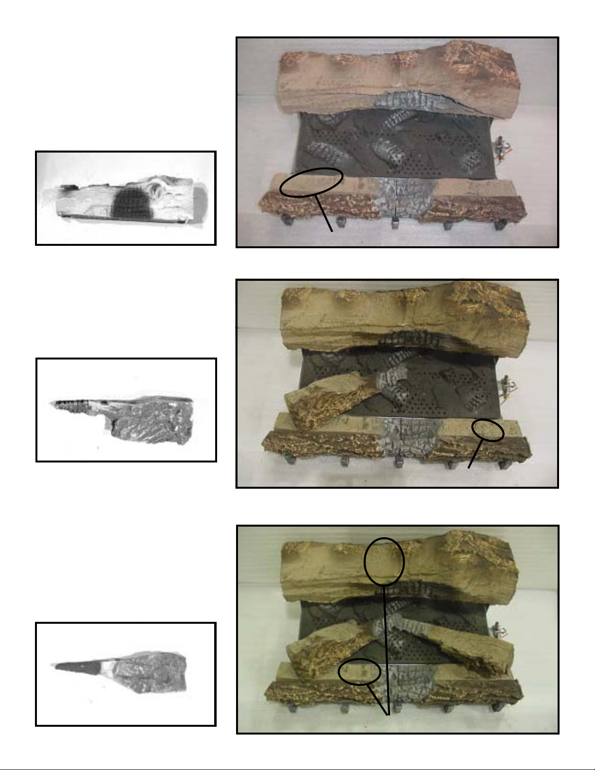
LOG #5: (SRV481-701)
This log sits towards the back on top of the
brackets located on the right and the left. The
two notches on the bottom of the log should
rest over these brackets. For NG units the
back of this log should line up with the back
end of the brackets. For LP units the back of
this log should be recessed a 1/2-inch from
the back of the brackets.
5
LOG #6: (SRV481-705)
Set log #6 on the top of log #1 and the burner
towards the left by following the flat spot mark
(on log #1). Make sure that the log will clear
the ports on the top of the burner .
5
FLAT SPOT (For use to place log #6)
6
LOG #7: (SRV446-702)
Set log #7 on the top of log #2 to the right
(use flat spot). The pointed end should be
towards the center of the burner, and should
rest underneath the pointed end of log #6.
(Y ou should tilt up log #6 while you are doing
that). Make sure that the log will clear the
ports on the top of the burner .
7
6
FLAT SPOT (For log #7)
7
FLAT SPOTS (For log #8)
2
 Loading...