

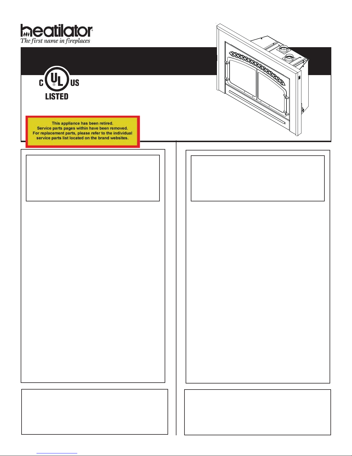
Heatilator ADI60 Installer's Manual
Installers Guide
Guide d’installation
Underwriters Laboratories Listed
Homologué Underwriters Laboratories
Model/Modèle:
WARNING: If the information in these
instructions is not followed exactly, a
fire or explosion may result causing
property damage, personal injury or
death.
- Do not store or use gasoline or other
flammable vapors and liquids in the vicinity of this or any other appliance.
- WHAT TO DO IF YOU SMELL GAS:
• Do not try to light any appliance.
• Do not touch any electrical switch.
• Do not use any phone in your
building.
• Immediately call your gas supplier
from a neighbor's phone. Follow the
gas supplier's instructions.
• If you cannot reach your gas sup-
plier, call the fire department.
- Installation and service must be
performed by a qualified installer,
service agency, or the gas supplier.
ADI60
AVERTISSEMENT : Si ces instructions
ne sont pas suivies à la lettre, un
incendie ou une explosion pourraient en
résulter, causant des dommages
matériels, des blessures ou la mort.
- N’entreposez ou n’utilisez jamais
d’essence ou autres vapeurs et liquides
inflammables à proximité de cet appareil
ou de tout autre appareil.
- QUE FAIRE SI VOUS SENTEZ UNE
ODEUR DE GAZ :
• Ne tentez d’allumer aucun appareil.
• Ne touchez aucun interrupteur
électrique.
• N’utilisez aucun téléphone dans votre
édifice.
• Appelez immédiatement votre
fournisseur de gaz vous servant du
téléphone d’un voisin. Suivez les instructions du fournisseur de gaz.
• Si vous ne pouvez pas atteindre votre
fournisseur de gaz, appelez le service
des incendies.
- L’installation et l’entretien doivent être
effectués par un installateur qualifié, une
agence de maintenance ou le fournisseur de gaz.
In the Commonwealth of Massachusetts:
• installation must be performed by a licensed plumber
or gas fitter;
• a CO detector shall be installed in the room where
the appliance is installed.
Dans la République de Massachusetts :
• l'installation doit être exécutée par un plombier
autorisé ou un monteur de gaz ;
• un CO le détecteur sera installé dans la pièce où
l'appareil est installé.
Heatilator • ADI60 • 345-900EF Rev. G • 2/06
1
WARNING: Improper installation, adjustment,
alteration, service or maintenance can cause
injury or property damage. Refer to this
manual.
For assistance or additional information consult a qualified installer, service agency or the
gas supplier.
Read this manual before installing or operating this appliance. This Installers Guide must
be left with appliance for future reference.
AVERTISSEMENT : Une installation, un réglage,
une modification, une réparation ou un service
incorrects risquent d’entraîner des blessures ou
des dommages matériels. Consultez ce manuel.
Pour obtenir de l’aide ou des informations
supplémentaires, consultez un installateur
qualifié, une agence de maintenance ou le
fournisseur de gaz.
Lisez ce manuel avant d’installer ou d’utiliser
cet appareil. Ce Guide d’installation doit rester
avec l’appareil pour référence ultérieure.
1. This appliance may be installed in an aftermarket,
permanently located, manufactured (mobile) home,
where not prohibited by local codes.
2. This appliance is only for use with the type of gas
indicated on the rating plate. This appliance is not
convertible for use with other gases, unless a certified
kit is used.
SAFETY AND WARNING
!
INFORMATION
READ and UNDERSTAND all instructions
!
carefully before starting the installation. FAILURE
TO FOLLOW these installation instructions may
result in a possible fire hazard and will void the
warranty.
!
Prior to the first firing of the fireplace, READ Step
9 and Step 10 of this Installers Guide.
DO NOT USE this appliance if any part has been
!
under water. Immediately CALL a qualified
service technician to inspect the unit and to
replace any part of the control system and any
gas control which has been under water.
THIS UNIT IS NOT FOR USE WITH SOLID FUEL.
!
Installation and repair should be PERFORMED
!
by a qualified service person. The appliance and
venting system should be INSPECTED before
initial use and at least annually by a professional
service person. More frequent cleaning may be
required due to excessive lint from carpeting,
bedding material, etc. It is IMPERATIVE that the
unit’s control compartment, burners, and
circulating air passageways BE KEPT CLEAN
to provide for adequate combustion and ventilation
air.
Always KEEP the appliance clear and free from
!
combustible materials, gasoline, and other
flammable vapors and liquids.
1. Cet appareil peut être installé dans un mobile home
préfabriqué, qui a été vendu et ne sera plus déplacé,
si les codes locaux l’autorisent.
2. Cet appareil est conçu pour être utilisé seulement avec
le type de gaz indiqué sur la plaque signalétique. Cet
appareil ne peut être converti à l’utilisation d’autres
gaz qu’avec un module homologué.
CONSIGNES DE SÉCURITÉ ET
!
MISES EN GARDE
LISEZ ATTENTIVEMENT toutes les instructions
!
avant de commencer l’installation. Si ces
instructions d’installation ne sont pas suivies, un
risque d’incendie pourrait en résulter et la garantie
sera annulée.
Avant l’allumage initial, LISEZ étapes 9 et 10 du
!
présent guide de l’installateur.
N’UTILISEZ PAS cet appareil si une pièce a été
!
submergée. APPELEZ immédiatement un
technicien de service qualifié pour l’inspection de
l’appareil et le remplacement de toute pièce qui
fut submergée.
CET APPAREIL N’EST PAS CONÇU POUR
!
ÊTRE UTILISÉ AVEC DES COMBUSTIBLES
SOLIDES.
L’installation et les réparations doivent être
!
EFFECTUÉES par un technicien de service
qualifié. L’appareil et le système d’évacuation doivent
être INSPECTÉS avant la première utilisation et au moins
une fois l’an par un technicien professionnel. Un nettoyage
plus fréquent peut s’avérer nécessaire en cas
d’accumulation de fibres de tapis, de literie, etc. Il est
IMPÉRATIF que le boîtier de commandes, les brûleurs
et les conduits d’air de circulation de l’appareil RESTENT
PROPRES afin de permettre une circulation suffisante
d’air de combustion et de ventilation.
2
Ne PLACEZ jamais de matériaux combustibles,
essence ou autres vapeurs ou liquides inflammables
!
à proximité de l’appareil.
Heatilator • ADI60 • 345-900EF Rev. G • 2/06
NEVER OBSTRUCT the flow of combustion and
!
ventilation air. Keep the front of the appliance
CLEAR of all obstacles and materials for servicing
and proper operations.
N’OBSTRUEZ JAMAIS la circulation d’air de
!
combustion et de ventilation. Maintenez l’avant de
l’appareil DÉGAGÉ de tout obstacle et matériau afin
d’en permettre le service et le bon fonctionnement.
Due to the high temperature, the appliance should
!
be LOCATED out of traffic areas and away from
furniture and draperies. Clothing or flammable
material SHOULD NOT BE PLACED on or near
the appliance.
Children and adults should be ALERTED to the
!
hazards of high surface temperature and should
STAY AWAY to avoid burns or clothing ignition.
Young children should be CAREFULLY
SUPERVISED when they are in the same room as
the appliance.
These units MUST use one of the vent systems
!
described in the Installing the Insert section of the
Installers Guide. NO OTHER vent systems or
components MAY BE USED.
This gas fireplace and vent assembly MUST be
!
vented directly to the outside and MUST NEVER
be attached to a chimney serving a separate solid
fuel burning appliance. Each gas appliance MUST
USE a separate vent system. Common vent
systems are PROHIBITED.
INSPECT the external vent cap on a regular basis
!
to make sure that no debris is interfering with the
air flow.
The glass door assembly MUST be in place and
!
sealed, and the trim door assembly MUST be in
place on the fireplace before the unit can be placed
into safe operation.
DO NOT OPERATE this appliance with the glass
!
door removed, cracked, or broken. Replacement
of the glass door should be performed by a
licensed or qualified service person. DO NOT strike
or slam the glass door.
The glass door assembly SHALL ONLY be
!
replaced as a complete unit, as supplied by the
gas fireplace manufacturer. NO SUBSTITUTE
material may be used.
DO NOT USE abrasive cleaners on the glass door
!
assembly. DO NOT ATTEMPT to clean the glass
door when it is hot.
Turn off the gas before servicing this appliance. It
!
is recommended that a qualified service technician
perform an appliance checkup at the beginning of
each heating season.
Any safety screen or guard removed for servicing
!
must be replaced before operating this appliance.
DO NOT place furniture or any other combustible
!
household objects within 36 inches of the fireplace front.
En raison de la température élevée, l’appareil doit
!
SE TROUVER en dehors des zones de passage et
à bonne distance des meubles et des rideaux. NE
PLACEZ JAMAIS DE vêtements OU matériaux
inflammables sur l’appareil ou à proximité.
Les enfants et les adultes doivent être AVERTIS
!
des risques que présentent les surfaces à haute
température et doivent RESTER À L’ÉCART afin
d’éviter les brûlures et l’enflammement de
vêtements. Les enfants en bas âge doivent être
SURVEILLÉS ATTENTIVEMENT lorsqu’ils se
trouvent dans la même pièce que l’appareil.
Ces appareils DOIVENT utiliser l’un des systèmes
!
d’évacuation décrits dans la section intitulée
Installation de la cassette dans le Guide
d’installation. AUCUN AUTRE système ou élément
d’évacuation NE PEUT ÊTRE UTILISÉ.
Cet appareil à gaz et ce système d’évacuation
!
DOIVENT évacuer les gaz de combustion
directement à l’extérieur et NE DOIVENT JAMAIS
être raccordés à une cheminée desservant un autre
appareil à combustible solide. Chaque appareil à gaz
DOIT UTILISER un système d’évacuation distinct.
L’utilisation de systèmes d’évacuation en commun
est INTERDITE.
INSPECTEZ régulièrement le capuchon d’évacu-
!
ation extérieur afin de vous assurer que la circulation
de l’air ne soit pas entravée par des débris.
La porte en verre DOIT être en place et hermé-
!
tiquement fermée, et l’ensemble de la porte de
garniture DOIT être en place sur le foyer pour que
l’appareil puisse fonctionner en toute sécurité.
NE FAITES PAS FONCTIONNER cet appareil si la
!
porte en verre est démontée, fêlée ou brisée. La
porte en verre doit être changée par un technicien
de service agréé ou qualifié. NE frappez et NE
claquez PAS la porte en verre.
La porte en verre DOITêtre changée UNIQUEMENT
!
en tant qu’unité complète, telle qu’elle est fournie
par le fabricant du foyer à gaz. AUCUNmatériau DE
SUBSTITUTION ne peut être utilisé.
N’UTILISEZ PAS de produits d’entretien abrasifs
!
sur la porte en verre. N’ESSAYEZ PAS de nettoyer
la porte en verre lorsqu’elle est chaude.
Fermez le gaz avant d’effectuer le service de cet
!
appareil. Il est conseillé qu’un technicien de service
qualifié inspecte l’appareil au début de chaque saison
de chauffage.
Tous les écrans et dispositifs de protection démontés
!
pour le service doivent être remis en place avant
l’utilisation de cet appareil.
NE placez NI meubles, NI autres objets ménagers
combustibles à moins de 91,44 cm (36 pouces) de la
!
façade du foyer.
Heatilator • ADI60 • 345-900EF Rev. G • 2/06
3

Table of Contents
Table des matières
Safety and Warning Information ............................... 2
Î Í
Service Parts List ........................................................5
Section 1: Approvals and Codes ...............................8
Approval Listing and Codes ............................................ 8
Appliance Certification ....................................................8
Installation Codes ..........................................................8
High Altitude Installations ...............................................8
Section 2: Getting Started ......................................... 9
Introducing the Heatilator Gas Appliances .................... 9
Pre-installation Preparation .............................................9
Venting and Installation ................................................ 10
Section 3: Installing the Insert ................................. 14
Step 1 Installing the Vent System ............................... 14
Vent System Approvals ................................... 14
Step 2 Positioning, Leveling, and
Securing the Insert ..........................................19
Step 3 The Gas Control Systems ............................... 19
Step 4 The Gas Supply Line .......................................20
Step 5 Gas Pressure Requirements ............................ 21
Step 6 Wiring the Fireplace ........................................ 22
Step 7 Installing Logs and Ember Material .................. 24
Positioning the Logs ........................................ 24
Shutter Settings .............................................. 24
Placing the Ember Material .............................. 24
Step 8 Installing the Trim Surrounds ........................... 26
Step 9 Before Lighting the Appliance........................... 28
Step10 Lighting the Appliance ..................................... 29
After the Installation......................................... 31
Consignes de sécurité et mises en garde.................. 2
Liste des pièces de rechange ................................... 5
Section 1 : Homologations et codes .......................... 8
Homologations et codes .................................................. 8
Homologation de l’appareil ............................................... 8
Codes d’installation ......................................................... 8
Installation à haute altitude .............................................. 8
Section 2 : Comment débuter..................................... 9
Présentation des appareils à gaz Heatilator ................... 9
Préparation avant l’installation .......................................... 9
Évacuation et installation ............................................... 10
Section 3 : Installation de la cassette ...................... 14
Étape 1 Installation du système d’évacuation ............... 14
Homologation du système d’évacuation .......... 14
Étape 2 Emplacement, nivellement et solidification
de la cassette ................................................ 19
Étape 3 Systèmes de commande de gaz .................... 19
Étape 4 Conduit à gaz ................................................ 20
Étape 5 Spécifications de la pression du gaz ............... 21
Étape 6 Filage électrique du foyer ............................... 22
Étape 7 Installation des bûches et des braises ............ 24
Mise en place des bûches ............................. 24
Fixations d’obturateur .................................... 24
Mise en place des braises ............................. 24
Étape 8 Installation des entourages ............................. 26
Étape 9 Avant d’allumer l’appareil ................................ 28
Étape 10 Allumage de l’appareil .................................... 29
Après l’installation .......................................... 31
Section 4: Maintaining and Servicing
Your Appliance ....................................... 31
Section 5: Troubleshooting ...................................... 33
Limited Lifetime Warranty ....................................... 37
Î = Contains updated information.
4
Section 4 : Entretien et service de votre appareil .. 31
Section 5: Dépannage.............................................. 33
Limited Lifetime Warranty ........................................ 38
Î = Contient des informations mises à jour.
Heatilator • ADI60 • 345-900EF Rev. G • 2/06
1Approvals and Codes
Homologations et codes
Approval Listing and Codes
Appliance Certification
The Heatilator models discussed in this Installers Guide have
been tested to certification standards and listed by the
applicable laboratories.
CERTIFICATION STANDARD
MODEL ADI60
LABORATORY Underwriters Laboratories
TYPE Direct Vent Gas Fireplace Heater
STANDARD ANSI Z21.88•CSA2.33•UL307B
Installation Codes
The appliance installation must conform to local codes.
Before installing the appliance, consult the local building
code agency to ensure that you are in compliance with all
applicable codes, including permits and inspections.
In the absence of local codes, the appliance installation must
conform to the National Fuel Gas Code ANSI Z223.1 (in the
United States) or the CAN/CGA-B149 Installation Codes (in
Canada). The appliance must be electrically grounded in
accordance with local codes or, in the absence of local codes
with the National Electric Code ANSI/NFPA No. 70 (in the
United States), or to the CSA C22.1 Canadian Electric Code
(in Canada).
These models may be installed in a bedroom or bed-sitting
room in the U.S.A. and Canada.
High Altitude Installations
U.L. Listed gas appliances are tested and approved without
requiring changes for elevations from 0 to 2,000 feet in the
U. S. A. and in Canada.
When installing this appliance at an elevation above 2,000
feet, it may be necessary to decrease the input rating by
changing the existing burner orifice to a smaller size. Input
rate should be reduced by 4% for each 1000 feet above a
2000 foot elevation in the U.S.A. or 10% for elevations
between 2000 and 4500 in Canada. If the heating value of
the gas has been reduced, these rules do not apply. To
identify the proper orifice size, check with the local gas utility.
If installing this appliance at an elevation above 4,500 feet
(in Canada), check with local authorities.
Homologations et codes
Homologation de l’appareil
Les modèles Heatilator dont il est question dans ce Guide
d’installation ont été testés conformément aux normes
d’homologation et ont été approuvés par les laboratoires
compétents.
NORME D’HOMOLOGATION
MODÈLE ADI60
LABORATOIRE Underwriters Laboratories
TYPE Cassette de cheminée à gaz à
système d’évacuation directe
NORMES ANSI Z21.88•CSA2.33•UL307B
Codes d’installation
L’installation de l’appareil doit être conforme aux codes
locaux. Avant d’installer l’appareil, consultez les autorités
locales en matière de codes de construction afin de vous
assurer que vous respectez tous les codes en vigueur, y
compris les permis de construire et les inspections.
En l’absence de codes locaux, l’installation de l’appareil doit
être conforme au code américain National Fuel Gas Code
ANSI Z223.1 (aux États-Unis) ou aux Codes des installations
CAN/CGA-B149 (au Canada). L’appareil doit être muni d’un
fil de terre conformément aux codes locaux ou, en l’absence
de codes locaux, au code américain National Electric Code
ANSI/NFPA n°70 (aux États-Unis) ou au Code électrique
canadien CSA C22.1 (au Canada).
Ces modèles peuvent être installés dans une chambre à
coucher ou une chambre-salon aux États-Unis et au Canada.
Installation à haute altitude
Les appareils à gaz homologués U.L. ont été testés et
approuvés pour être utilisés sans modification à des altitudes
comprises entre 0 et 610 mètres (0 et 2 000 pieds) aux
États-Unis et au Canada.
Si cet appareil est installé à une altitude supérieure à 610
mètres, il peut s’avérer nécessaire de réduire l’admission
du gaz en diminuant l’ouverture de l’orifice du brûleur. Le
débit calorifique doit être réduit de 4 % tous les 305 mètres
(1 000 pieds) au-dessus de 610 mètres d’altitude (2 000
pieds) aux États-Unis ou de 10 % entre 610 et 1 372 mètres
d’altitude (2 000 et 4 500 pieds) au Canada. Si le pouvoir
calorifique du gaz a été réduit, ces règles ne s’appliquent
pas. Pour connaître l’ouverture de l’orifice qui convient,
consultez le service local de distribution de gaz.
Si cet appareil est installé à une altitude supérieure à 1.370
mètres (au Canada), consultez les autorités locales.
8
Heatilator • ADI60 • 345-900EF Rev. G • 2/06
2
Getting Started
Comment débuter
Introducing the Heatilator
Gas Appliance
Heatilator direct vent gas appliances are designed to operate with all combustion air siphoned from outside of the building and all exhaust gases expelled to the outside. The information contained in this Installers Guide, unless noted otherwise, applies to all models and gas control systems. Gas
appliance diagrams, including the dimensions, are shown in
this section.
Pre-installation Preparation
This gas insert and its components are tested and safe when
installed in accordance with this Installers Guide. Report to
your dealer any parts damaged in shipment, particularly the
condition of the glass. Do not install any unit with
damaged, incomplete, or substitute parts.
The vent system components and trim surrounds are shipped
in separate packages. The gas logs are packaged separately
and must be field installed. Read all of the instructions
before starting the installation. Follow these instructions
carefully during the installation to ensure maximum
safety and benefit. Failure to follow these instructions
will void the owner’s warranty and may present a fire
hazard.
The Heatilator Warranty will be voided by, and Heatilator
disclaims any responsibility for, the following actions:
• Installation of any damaged appliance or vent system
component.
• Modification of the appliance or direct vent system.
• Installation other than as instructed by Heatilator.
• Improper positioning of the gas logs or the glass door.
• Installation and/or use of any component part not manufactured and approved by Heatilator not withstanding any
independent testing laboratory or other party approval of
such component part or accessory.
ANY SUCH ACTION MAY POSSIBLY CAUSE A FIRE
HAZARD.
Présentation des appareil à gaz
Heatilator
Les appareils à gaz à évacuation directe Heatilator sont
conçus pour aspirer tout l’air de combustion de l’extérieur de
l’édifice et expulser tous les gaz de combustion en dehors
de l’édifice. Les informations contenues dans ce Guide
d’installation, sauf dans le cas de mention contraire,
s’appliquent à tous les modèles et à tous les systèmes de
commande de gaz. Cette section comprend des schémas
de l’appareil à gaz, avec ses dimensions.
Préparation avant l’installation
Cette cassette à gaz et ses éléments ont été testés et ne
présentent aucun danger s’ils sont installés conformément
à ce Guide d’installation. Signalez à votre concessionnaire
toutes pièces endommagées lors du transport, en particulier
s’il s’agit de la porte en verre. N’installez aucun appareil
dont des pièces sont endommagées, sont incomplètes
ou ont été remplacées par des pièces différentes.
Les éléments du système d’évacuation et les entourages
sont expédiés dans différents colis. Les bûches à gaz sont
emballées séparément et doivent être installées sur place.
Lisez toutes les instructions avant de commencer
l’installation. Suivez attentivement ces instructions
pendant l’installation afin d’assurer une sécurité et une
efficacité optimales. Si ces instructions ne sont pas
suivies, la garantie sera annulée et vous pourriez
causer un incendie.
La garantie Heatilator, sera annulée par les actes suivants,
pour lesquels Heatilatordécline toute responsabilité :
• Installation d’éléments endommagés dans l’appareil ou
dans le système d’évacuation.
• Modification de l’appareil ou du système d’évacuation
directe.
• Installation différente de celle indiquée par Heatilator.
• Placement incorrect des bûches à gaz ou de la porte en
verre.
• Installation et/ou utilisation de pièces n’ayant pas été
fabriquées et approuvées par Heatilator , même si cette
pièce ou cet accessoire a été homologué par un laboratoire
d’essais indépendant ou un autre organisme compétent.
CES ACTES POURRAIENT CAUSER UN INCENDIE.
WARNING: This appliance is tested and
!
listed for use only with the approved optional accessories. Use of optional accessories not specifically tested for this appliance
could void the appliance warranty and/or result in a safety hazard.
AVERTISSEMENT! Cet appareil a été testé et
!
homologué uniquement pour une utilisation
avec les accessoires facultatifs approuvés. L’utilisation
d’accessoires facultatifs qui n’ont pas été
spécifiquement testés pour cet appareil peut annuler
la garantie de l’appareil et/ou présenter un danger.
Heatilator • ADI60 • 345-900EF Rev. G • 2/06
9
Getting Started (continued)
Comment débuter (suite)
VENTING AND INSTALLATION
1. Heatilator gas inserts are designed for recessed installations into solid fuel Masonry or Factory Built Non Combustible fireplaces that have been installed in accordance
with the National, Provincial, State and local building
codes.
2. Minimum fireplace opening requirements are shown in
Figure 2 of this installation manual. The firebrick (refractory) can be removed from a factory built fireplace in order to gain minimum gas insert opening requirements.
3. This insert requires no hearth extensions. Combustible
material on the floor may be installed up to the insert. Do
not obstruct the lower grill of the insert. The original fireplace cannot be returned to solid fuel in this condition.
4. The metal floor of the solid fuel firebox may be removed
to facilitate the installation of the insert.
TO COMBUSTIBLE MATERIAL UNDER THE INSERT IS 1/4”. YOU MUST USE THE LEVELING
LEGS TO RAISE THE INSERT A MINIMUM OF 1/4”
IF THE INSERT IS TO SIT ON COMBUSTIBLE
MATERIAL.
box may not be altered with the exception of removable
baffles and dampers. The original fireplace cannot be returned to solid fuel in this condition.
5. Combustible facing material may be installed over the
original combustible or non-combustible facing material
on the solid fuel fireplace. The original specified clearances of a factory-built fireplace must be maintained,
with the exception of the hearth. Clearances on a masonry fireplace must be maintained at 12” from the opening for combustible projections over 1 1/2”. Clearances
for combustible projections under 1 1/2” must be maintained at 6” from the opening per NFPA 211. Plan the
surround size accordingly. A surround must be used
with the insert. UNDER NO CIRCUMSTANCE CAN COMBUSTIBLE MATERIAL BE PLACED BEHIND THE SURROUND!
6. The insert surround is tested and approved with this gas
insert and may cover existing air circulation vents or grills
on the solid fuel fireplace it is installed into. Should the
surround not cover the entire ventilation grill surface, the
grill should be left open.
NOTE: Decorative trim surrounds have been tested and
approved to cover existing air circulation vents or grills.
WARNING: Only the surround as supplied,
!
may be used to cover integral grills on the
solid fuel-burning fireplace. No other
components such as shrouds, sheet metal
plates, etc. may be used to seal off vents.
The side walls and top structure of the fire-
CLEARANCE
ÉVACUATION ET INSTALLATION
1. Les cassettes à gaz Heatilator sont conçues pour être
encastrées dans des cheminées en matériaux non combustibles, en maçonnerie ou préfabriquées, à combustible
solide, qui ont été installées conformément aux codes de
construction nationaux, provinciaux et locaux.
2. Les spécifications d’ouverture minimum de la cheminée
sont indiquées sur la Figure 2 de ce manuel d’installation.
Les briques réfractaires peuvent être retirées d’une
cheminée préfabriquée afin d’obtenir l’ouverture minimum
spécifiée pour la cassette à gaz.
3. Cette cassette ne nécessite pas de prolongement de
l’âtre. Des matériaux combustibles peuvent être installés
sur le plancher jusqu’au niveau de la cassette. N’obstruez
pas la grille inférieure de la cassette. Le foyer d’origine
ne peut pas être réutilisé avec un combustible solide
dans cet état.
4. Le plancher métallique du foyer à combustible solide peut
être démonté pour faciliter l’installation de la cassette.
LE DÉGAGEMENT ENTRE LES MATÉRIAUX
COMBUSTIBLES ET LE DESSOUS DE LA CASSETTE
EST DE 6,4 MM (1/4 PO). VOUS DEVEZ UTILISER LES
PIEDS DE NIVELLEMENT POUR ÉLEVER LA
CASSETTE D’AU MOINS 6,3 MM (1/4 PO) SI ELLE DOIT
REPOSER SUR UN MATÉRIAU COMBUSTIBLE. Les
parois latérales et la structure du dessus du foyer ne
doivent pas être modifiées, à l’exception des déflecteurs
et des registres démontables. Le foyer d’origine ne peut pas
être réutilisé avec un combustible solide dans cet état.
5. Un revêtement combustible peut être posé sur le
revêtement d’origine du foyer à combustion solide, qu’il
soit combustible ou pas. Les dégagements spécifiés à
l’origine doivent être maintenus autour d’un foyer
préfabriqué, à l’exception de l’âtre. Sur une cheminée en
maçonnerie, des dégagements de 30,48 cm (12 po.)
doivent être maintenus entre l’ouverture et les saillies
combustibles de plus de 38 mm (1,5 po.). Des dégagements de 15,24 cm (6 po.) doivent être maintenus entre
les saillies combustibles de moins de 38 mm (1,5 po.) et
l’ouverture, conformément à la norme NFPA 211.
Déterminez les dimensions de l’entourage en
conséquence. Il est nécessaire d’utiliser un entourage
avec la cassette. DES MATÉRIAUX COMBUSTIBLES NE
DOIVENT JAMAIS ÊTRE PLACÉS DERRIÈRE
L’ENTOURAGE!
6. À l’issue des essais auxquels il a été soumis, l’entourage
de cassette est apte à être utilisé avec cette cassette à
gaz. Il peut également couvrir les conduits ou les grilles
de circulation d’air existants du foyer à combustible solide
dans lequel celle-ci est installée. Si l’entourage ne couvre
pas toute la surface de la grille de ventilation, la grille doit
rester ouverte.
REMARQUE : À l’issue d’essais auxquels ils ont été
soumis, les entourages décoratifs sont aptes à couvrir
les conduits ou les grilles de circulation d’air existants.
AVERTISSEMENT : Seul l’entourage
!
d’origine peut être utilisé pour couvrir la
surface totale des grilles du foyer à
combustible solide. Aucun autre élément, tel
qu’une enveloppe de foyer, une tôle, etc., ne doit
être utilisé pour boucher les conduits d’évacuation.
10
Heatilator • ADI60 • 345-900EF Rev. G • 2/06
Getting Started (continued)
Comment débuter (suite)
7. To assure top performance, safety and efficiency, inserts
must be installed with an approved flue liner as per CAN/
CGA B-149 or National Fuel Code ANSI Z223 and these
instructions.
WARNING: THE SOLID FUEL FIREPLACE HAS
!
BEEN CONVERTED FOR USE WITH GAS ONLY
AND CANNOT BE USED FOR BURNING WOOD OR
SOLID FUELS UNLESS ALL ORIGINAL PARTS
HAVE BEEN REPLACED AND THE FIREPLACE HAS
BEEN REAPPROVED BY THE AUTHORITY HAVING
JURISDICTION.
8. The solid fuel fireplace’s flue damper must be fully locked
in the open position or removed for installation.
9. The chimney must be cleaned and in good working order
and constructed of noncombustible materials.
10.Make sure that all chimney cleanouts fit properly so air
cannot leak into the chimney.
11. Install the insert without the trim surround and make all
gas, venting, and electrical connections.
If the factory built fireplace has no gas access
!
holes provided, an access hole of 1” diameter
(25mm) or less may be drilled through the
lower sides or bottom of the combustion chamber
in a proper workmanship like manner.
7. Afin d’obtenir des performances, une sécurité et une
efficacité optimales, les cassettes doivent être installées
avec un revêtement de conduit approuvé, conformément
aux codes CAN/CGA B-149 ou au code américain Na-
tional Fuel Code ANSI Z223 et à ces instructions.
AVERTISSEMENT : LA CHEMINÉE À COM-
!
BUSTIBLE SOLIDE A ÉTÉ CONVERTIE POUR
ÊTRE UTLISÉE SEULEMENT AVEC DU GAZ ET NE
PEUT PLUS ÊTRE UTILISÉE POUR BRÛLER DU BOIS
OU D’AUTRES COMBUSTIBLES SOLIDES, À MOINS
QUE TOUTES LES PIÈCES D’ORIGINE NE SOIENT
REMISES EN PLACE ET QUE LA CHEMINÉE N’AIT
ÉTÉ À NOUVEAU APPROUVÉE PAR LES AUTORITÉS
COMPÉTENTES.
8. Le registre du tuyau de la cheminée à combustible solide
doit être verrouillé en position d’ouverture maximale ou
bien démonté pour l’installation.
9. La cheminée doit être nettoyée, en bon état de fonctionnement et composée de matériaux non combustibles.
10.Vérifiez que toutes les portes de ramonage soient bien
ajustées afin que l’air ne puisse pas entrer dans la
cheminée.
11. Installez la cassette sans l’entourage et effectuez tous
les raccords de gaz et d’évacuation, ainsi que tous les
branchements électriques.
12.Install decorative trim surround. Please refer to instructions included with the trim surround.
Ensure there are no obstructions to side air
!
passages of decorative trim once installed
on insert.
Si la cheminée préfabriquée ne comporte
aucun orifice d’arrivée de gaz, un orifice
!
d’accès de 25 mm de diamètre maximum peut
être percé au bas des parois latérales ou au fond
du foyer, de manière appropriée.
12.Installez l’entourage décoratif. Veuillez consulter les instructions incluses avec l’entourage.
Une fois l’entourage décoratif installé sur la
!
cassette, vérifiez que ses conduits d’air
latéraux ne soient pas obstrués.
Heatilator • ADI60 • 345-900EF Rev. G • 2/06
11
Getting Started (continued)
Comment débuter (suite)
When planning a fireplace insert installation, it’s necessary
to determine:
• The vent system configuration to be used.
• Gas supply piping.
• Whether optional accessories—devices such as a wall
switch, or remote control—are desired.
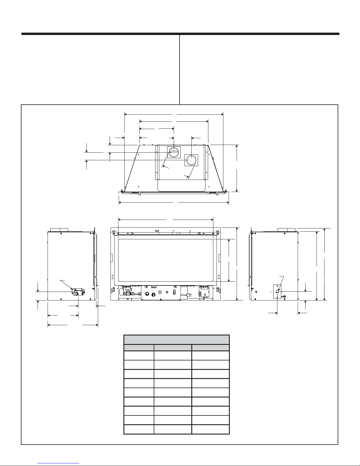
Figure 1. Diagram (All models)
Dimensions in brackets
are millimeters.
2-5/16 58.4[]
2-5/32 54.9[]
4-7/16
112.4[]
C
A
B
5-5/32
130.7[]
REF8-7/16
214.5[]
D
Avant de commencer l’installation de la cassette de cheminée,
il est nécessaire de déterminer :
• La configuration du système d’évacuation qui sera utilisée.
• La tuyauterie d’alimentation en gaz.
• Si vous désirez installer des accessoires facultatifs
(dispositifs tels qu’un interrupteur mural ou une commande
à distance).
Figure 1. Schéma
Les dimensions entre
crochets sont exprimées
en millimètres.
13-23/32
348.3[]
2-17/32
64.3[]
GAS INLET
8-29/32
226.5[]
14-11/16
372.9[]
5.296
134.51[]
E
MODEL DIMENSIONS
Location Inches Milimeters
A 29-1/32 737.1
B 20-5/32 512.3
C 10-3/32 256
D 32-5/16 820.8
E 27-25/32 705.8
F 12-7/16 316.1
G 22-23/32 577
H 20-1/4 514.3
I 21-5/32 537.2
F
G
ELECTRICAL
ACCESS
2-19/32
65.9[]
6-1/16
153.8[]
I
H
12
Heatilator • ADI60 • 345-900EF Rev. G • 2/06

Getting Started (continued)
Comment débuter (suite)
Figure 2. Insert Diagram
LOWER GRILLE /
GRILLAGE INFERIEUR
RATING PLATE /
PLAQUE DE CARACTERISTIQUES
GAS CONTROL VALVE /
VALVE DE COMMANDE DE GAZ
SURROUND /
ENTOURAGE
DOOR / PORTE
GLASS
ASSEMBLY /
PORTE EN
VERRE
Figure 2. Schéma de la cassette :
INLET AIR STARTING COLLAR /
COLLIER DE DEPART
D’ADMISSION D’AIR
EXHAUST STARTING
COLLAR /
COLLIER DE DEPART
D’ECHAPPEMENT
ON/OFF
SWITCH /
INTERRUPTEUR
MARCHE/ARRET
LOW VOLTAGE
WIR ES /
FILS DE BASSE
TENSION
GAS ACCESS /
ACCÈS DU CONDUIT
À GAZ
ELECTRICAL JUNCTION
BOX ACCESS /
ACCÈS DE BOÎTE DE
JONCTION ÉLECTRIQUE
B
C
TOP VIEW
(VUE DU DESSUS)
A
MINIMUM APPLIANCE SIZE / DIMENSIONS MINIMUM DE L'APPAREIL
Location Inches Millimeters
A Front Width / Largeur Avant 29-1/4 743
B Rear Width / Largeur Arriere 20-1/4 515
C Depth / Profondeur 13-5/8 346
* Height / Hauter 20-1/4 515
* NOTE: If exhaust collar on insert and fireplace damper do not line up, add 4 inches
(102mm) to minimum fireplace height for bends in vent pipe. / Remarque : Si le collet
d’évacuation de la cassette et le registre de la cheminée ne s’alignent pas, ajoutez 102 mm
à la hauteur minimale de la cheminée pour les coudes du conduit d’évacuation.
Heatilator • ADI60 • 345-900EF Rev. G • 2/06
13
3
Installing the Insert
Installation de la cassette
Step 1
Installing the Vent System
Vent System Installation Precautions
Before starting installation of vent kits, the installer should
read these instructions and the Vent Kit Instructions to
ensure that a proper vent installation is completed. Consult
your local Building Codes before beginning the Installation.
WARNING: THIS GAS INSERT AND VENT
!
ASSEMBLY MUST BE VENTED DIRECTLY TO
THE OUTSIDE AND MUST NEVER BE ATTACHED TO
A CHIMNEY SERVING A SEPARATE SOLID FUEL
BURNING APPLIANCE. EACH GAS APPLIANCE
MUST USE A SEPARATE VENT SYSTEM. COMMON
VENT SYSTEMS ARE PROHIBITED.
Vent System Approvals
Table 1 and Figures 3 through 5 show the vent termination
caps and systems approved for use with these models.
Approved vent system terminations are labeled for
identification. 3-inch diameter listed flexible aluminum or
stainless steel gas vent is used for both the incoming
combustion air and exhaust vent pipes. NO OTHER
VENTING SYSTEMS OR COMPONENTS MAY BE USED.
Detailed installation instructions are included with each vent
termination kit and should be used in conjunction with this
manual.
Horizontal Venting
The vent system on this model CANNOT be terminated
horizontally.
Vertical Venting
The vent pipes MUST be connected to the proper collars on
the unit AND the exhaust vent pipe MUST be connected to
the termination cap or the unit will not operate. The
combustion air vent pipe CAN be connected to the
termination cap or it can terminate inside the chimney. The
bottom opening of the chimney must be sealed around the
vent pipes if the combustion air vent is NOT connected to
the termination cap. Use unfaced fiberglass insulation to
seal around the vent pipes. The insulation may give off an
odor during the first hour of operation. See Figures 4, 5, and 6.
NOTE: The minimum vertical rise (exhaust vent) is 14 feet
and the maximum vertical rise is 50 feet. These dimensions
are measured from the starting collars of the unit to the end
of the last section of vent pipe. See dimension V in Figure 4.
14
Étape 1
Installation du système d’évacuation
Précautions d’installation du système d’évacuation
Avant de commencer à installer les modules d’évacuation,
l’installateur doit lire ces instructions et celles des modules
d’évacuation afin d’obtenir une installation correcte. Consultez
les codes de construction de votre région avant de commencer
l’installation.
AVERTISSEMENT : CETTE CASSETTE À GAZ ET
!
CE SYSTÈME D’ÉVACUATION DOIVENT ÉVACUER LES GAZ DE COMBUSTION DIRECTEMENT À
L’EXTÉRIEUR ET NE DOIVENT JAMAIS ÊTRE RACCORDÉS À UNE CHEMINÉE DESSERVANT UN AUTRE
APPAREIL À COMBUSTIBLE SOLIDE. CHAQUE APPAREIL À GAZ DOIT UTILISER UN SYSTÈME D’ÉVACUATION DISTINCT. L’UTILISATION DE SYSTÈMES
D’ÉVACUATION EN COMMUN EST INTERDITE.
Homologation du système d’évacuation
Le Tableau 1 et les Figures 3 à 5 représentent les capuchons
et les systèmes d’évacuation homologués pour utilisation
avec ces modèles. Les terminaisons de système d’évacuation
homologuées portent une étiquette d’identification. Des conduits flexibles homologués de 76 mm de diamètre, en aluminium ou en acier inoxydable, servent à l’aspiration de l’air
de combustion et à l’évacuation des gaz de combustion.
AUCUN AUTRE SYSTÈME OU ÉLÉMENT D’ÉVACUATION
NE PEUT ÊTRE UTILISÉ. Des instructions d’installation
détaillées sont incluses avec chaque module de terminaison
de système d’évacuation et doivent être utilisées en
conjonction avec ce manuel.
Évacuation horizontale
Le système d’évacuation de ce modèle NE PEUT PAS
comporter de terminaison horizontale.
Évacuation verticale
Les conduits DOIVENT être raccordés aux collets correspondants de l’appareil ET le conduit d’évacuation DOIT être
raccordé au capuchon pour que l’appareil puisse fonctionner.
Le conduit d’air de combustion PEUT être raccordé au
capuchon ou aboutir à l’intérieur de la cheminée. L’ouverture
inférieure de la cheminée doit être jointe hermétiquement aux
conduits si le conduit d’air de combustion n’est PAS raccordé
au capuchon. Utilisez l'isolant de fibre de verre sans
revêtement pour assurer l'étanchéité des conduits
d'évacuation. L'isolant peut dégager une odeur pendant la
première heure de fonctionnement du foyer. Voir Figures 4,
5, et 6.
REMARQUE : La longueur verticale (conduit d’évacuation)
doit être comprise entre 4,3 mètres et 15,2 mètres. Cette
dimension est mesurée entre les collets de raccord de
l’appareil et l’extrémité de la dernière section de conduit
d’évacuation. Voir la dimension V sur la Figure 4.
Heatilator • ADI60 • 345-900EF Rev. G • 2/06
 Loading...