

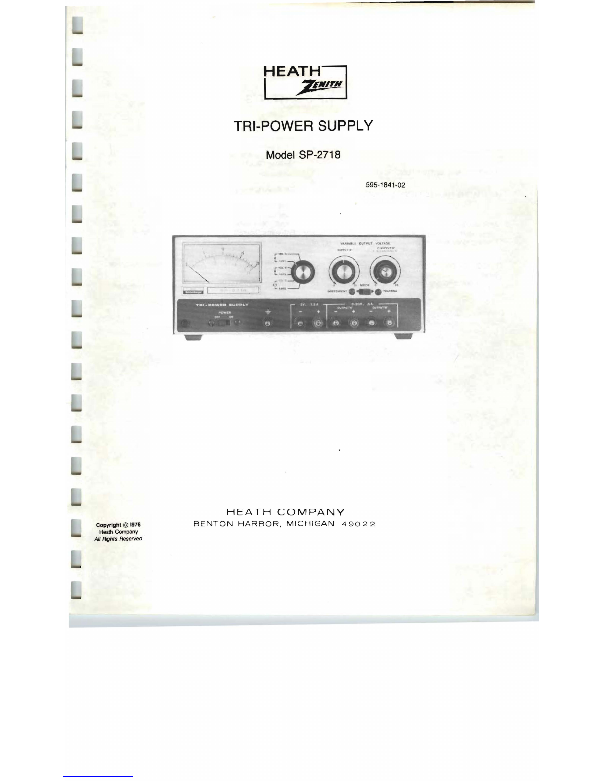
Heath Zenith SP-2718 Operation Manual
HEATH
.7'11"6
TRI-POWER SUPPLY
Model SP-2718
595-1841-02
"
I'
1
J1
__
1
r""u..'~
,
L,
__
r
••
L
.....
o.""'-""J ."
HEATH
COMPANY
Copyright © 1976
BENTON
HARBOR,
MICHIGAN
49022
Heath Company
All Rights Re.
served
Page 2
TABLE OF CONTENTS
SPECIFICATIONS . .
... ........
.. ..
. .
.. ... ... ..
..
. .. . 3
CIRCUIT DESCRIPTION
.........
. .. . ..
...
. . ...
...
14
OPERATION
..
. ..
...... ................ ...
. .
......
..
5
CONTROL AND SWITCH FUNCTIONS
...
. . . . . .
....
. . . 5
OPERATING PROCEDURES .
.. ..
. . .......... .. .
....
. 6
APPLICATIONS..
..
...
.. .. . ...
..
. .
..
...
. . .
...
.....
7
Circuit Board X-Ray View . . . . . . .
... . ....... . ...
..
..
. . 20
Tracking Mode Applications . . .
Schematic Diagram . .
... . ..
..
..
..
. .
..
..
..
. (Fold-in Page)
....
...
.. . ..
. .
..
. .
..
. . 9
IN
CASE
OF
DIFFICULTY
..
. .
....
..
... . .. . ........
. .
10
General ... .. ...
..........
. .
.......
. .
....
. . " ...... .
10
WARRANTY .
...... ....
. .
...
. .. ... .. . Inside front cover
Primary Circuit . . . . . . . . . . . . . . . . . . . . . . . . . . . . . . . . . .
..
14
5-Volt
Supply.
. . . . . . . . . . . . . . . . . . . . . . . . . . . . . . . . . . . .
14
20-Volt 'A' and 'B' Supplies
...... . ..
...
. .
....
..
. .
..
15
Metering Circuit. . . . . . . . . . . . . . . . . . . . . . . . . . . . . . . . . .. 15
CALIBRATION
.......... . ...... . ...
...
.. . ..
....
...
.16
APPENDIX
... . ........ . ...
..
........... . .....
. . .
...
18
Independent Mode Applications . . . . . . . . . . . . . . . . . . . . . . 7
Parts List
..
..
...
. .
...
.....................
. . .......
18
SERVICE INFORMATION
...
. .
.. ..
. . . " Inside rear cover
Troubleshooting Chart
.........
. .. .. .
...
. . ......12
Page 3
SPECIFICATIONS
Outputs ..
................ . , ... , ... ..
...
. ,
....
. .
'A' -Supply
..
.. . . . ... .. ............ .. ... .. ....
. .
'8'
-Supply
.. ..
. .. . .. . .. . ...........
. ..
........
.
Regulation
Load . ..
.....
. .. .
...
. . ...
...
. .. . .. . ..
..
. .. . .. .
Line
..
. .. .. ....
....
. ..
...
" .
.......
' " . . " ., .
Ripple
and
Noise . ... .
.............
. ..
......
. . .
Current Limiting
..
. . ...... .. .
...
....
. .. .
.. ..
.. . . .
Tracking Range
........ .. ....
. .. . .. . ...
...
. .. . . .
Tracking Error
..
. .. .. . .. . .. .
........
. .. ..
......
. .
Series Operation
......
..
...
. .
....
. . ... .. .
....
. . .
Parallel Operation . .
..
. .. ...... . .... ....
.. . . .
...
.
VOltage-Current Monitor Accuracy .
.. ..
. .
..
... . ...
.
5 volts
DC
::!::
5%
at 1.5 ampere.
0-20 volts
DC
at 0.5 ampere,
continuously adj,ustable.
0-20 volts
DC
at 0.5 ampere,
continuously adjustable.
Less than 0.1 % (20 mV) variation
from no load to full load
on
20-volt supplies.
Less than
3%
(150 mV) variation
from no load
to
full load
on
5-volt supply.
20-volt Supplies: Less than
0.2%
(40
mV) for a line
voltage change
of
10 volts.
5-volt Supply: Less than
0.2% (10
mV)
for a line
voltage change of 10 volts.
Less than 5 mV rms.
Limiting for each supply
fixed
slightly above rated current
to
provide short-circuit protection.
2 to 18 volts.
Less than 1 volt.
All three supplies may be
connected
in
series.
20-volt supplies may be operated
in
parallel by adding 0.
511
current-equalizing resistors (not supplied).
5%
of
full scale.
Page 4
Meter Ranges . . .
... . .... . ..
...
..............
. . .
Power Requirements
..
...
. .
...
..
..
...
.. ..
. . . .
..
.
Power Switching Overshoot (On-Off)
...
...
. . . .
..
. .
Voltage Control, 20-Volt Supplies A and B .
..
. . . . . . .
Dimensions .
.. ..
. .
.. ............
........
...
. .. . .
Weight
............
. . ... .
.......
. .
.............
.
Voltages, 0-20 and 0-5.5.
Current, 0-550 mA and 0-2A.
100-135 VAC or 200-270 VAC,
50/60 Hz, 100 watts at full load.
None.
Continuously variable ,
oto 20 volts.
4-1/2" high x 10-3/4" wide x
9"
deep
(11.43
cm
x 27.3
cm
x 22.86 cm).
10 Ibs
(3
.73 kg).
-
The Heath Company reserves the right to discontinue products and to change specifications
at any time without incurring any obligation
to
incorporate new features
in
products previously
sold.
Page 5
OPERATION
Refer
to
Figure 1
(on
the fold-in).
Before you use your Tri-Power Supply, you should become
entirely familiar with its capabilities, characteristics, and its
features. Study Figure 1 to learn each control and switch
function as you read this portion of the Manual.
CONTROL
AN,o
SWITCH FUNCTIONS
LINE AND POWER SWITCHES (SW2 and SW1)
Line switch SW2 is located on the underside of the chassis. If
the line voltage
in
your area
is
100-135 volts AC, use a screw-
driver tip
to
push the switch slide to expose the
"120"
on
the
slide. If the line voltage
in
your area
is
200-270 volts AC, push
the switch slide
to
expose the "240."
The POWER switch
on
the front panel is a simple slide switch
that applies the line voltage to the primary circuit
of
the power
transformer when you push the switch to the ON position.
At
the same time, power
is
applied to the pilot light to indicate that
power has been applied to the unit.
METER SWITCH (SW4)
It
is
important that you know that METER switch (SW4) does
not switch any output voltage or current. The switch permits
you
to
observe any of the Power Supply outputs on the meter,
whether voltage or current. The METER switch thus allows
you to monitor any of the variable outputs and
to
set them
accurately
to
any desired levels.
METER
Note that the meter scales are printed
in
two colors. The lower
scale,
in
red, corresponds to each of the METEr! switch func-
tions that also are lettered
in
red: "A-AMPS" (current flowing to
a load from the output of the A supply; uB-AMPS" (current
flowing to a load from the output of the B supply; and,
5V-VOL TS (the voltage available at the output of the 5-volt
supp.ly).
The
l:Jpper
meter scale,
in
black, corresponds to the following
METER switch functions, also printed in black:
"A
-VOLTS"
(the voltage at the output of the A supply); "B-VOL TS" (the
voltage at the output of the B supply); and, "5V-AMPS" (current flowing to a load from the output of the 5-volt supply) .
SUPPL Y A CONTROL (R7)
When you turn this control clockwise from its
"0"
position, the
output of front panel jacks J4 and J5 (OUTPUT A) will increase
from zero to any level up
to
20 volts and a load current up to
500 milliamperes. Read these levels on the meter when the
METER switch is either at "A-VOLTS" or at "A-AMPS."
NOTE:
In
the TRACKING mode of operation, Supply A control
R7
is
disabled; control of the 20-volt A-supply is transferred to
• A TRACKING B.control
RS
(the small red knob at the right
side of the front panel, which operates
as
a clutched control
with
0 SUPPLY B control R9).
o SUPPLY B CONTROL (R9)
Control
R9
is
half of the dual control at the right side of the front
panel. The other half of this control
is
turned with the small red
knob and is labeled
".
A TRACKING
B"
in
red lettering above
the two control knobs. The two controls are "clutched" together
in
such a manner that both controls will turn when either
knob is turned. Note that black knob
R9
corresponds
to
the
black letters
("0
SUPPLY B")
on
the panel just above the
control.
Control
R9
adjusts the amount of voltage at OUTPUT B jacks
J6 and J7. This control will vary the available B-supply voltage
from zero
to
20 volts DC and a load current up to 500 milliamperes. Read the output levels on the meter when the METER
switch is turned to B-VOL TS and to B-AMPS.
Page 6
• A TRACKING B CONTROL (RS)
Control
RS
is "clutched" to
"0
SUPPLY
B"
control A9. At any
time either control is turned, the other will turn with it. Since it
is
a friction action, either control may be operated independently
of the other, providing the other control
is
held
in
place. Control
RS
is enabled only when MODE switch SW3
is
in the TRACK-
ING position.
In
this manner, the A 20-volt supply is disabled at
SUPPLY A control R7, and is controlled by the small red knob
at
RS.
At no time are the electrical and electronic circuits of the
A and B 20-volt power supplies connected together internally.
MODE SWITCH (SW3)
In
the INDEPENDENT mode of operation, the 20-volt A supply
is connected
to
SUPPLY A control
R7
through the contacts of
the Mode switch.
In
this mode, the A-supply
is
"floating" and
control
R9
(small red knob) is disconnected from the circuit.
When MODE switch SW3
is
in
the TRACKING mode, control
A7 is removed from the circuit, and contro'l A9 is enabled and
the A-supply will track with the B-supply through the clutch
action of the dual control knobs.
OUTPUT JACKS (J1-J7)
Output jack
J1
is a chassis ground connection. If, at any time,
you wish to reference any of the three supplies to ground,
external connections from the appropriate supply jacks may
be connected to J 1 .
Jacks J2 and J3 are the connections for the fixed 5-volt,
1.5-ampere power supply.
Jacks J4 and J5 are the connections for the variable 20-volt,
500 milliampere A power supply.
Jacks J6 and J7 are the connections for the variable 20-volt,
500 milliampere B power supply .
OPERATING PROCEDURES
Two modes of operation are provided at the output jacks on
the front panel. These are the "Independent" and the "Tracking" modes. Each will be discussed under separate headings.
INDEPENDENT MODE
Each of the three power supplies
in
the Tri-Power supply may
be operated independently from one another, either floating or
referenced to another AC or DC source, or referenced to the
Tri-Power Supply ground connection at J1. In addition, any of
the separate supplies may be connected
in
series with external jumpers to provide up to 45 volts DC, referenced to any
external or internal level . NOTE: External references may not
exceed 200 volts.
TRACKING MODE
In
the TRACKING mode of operation, the 20-volt A and B
supplies are clutched together at the front panel dual control
RS/R9.
As either of the controls is turned, the other will turn
in
the same manner. To adjust the controls, the voltage output
must be observed on the meter for each 20-volt supply, and
the level of each set by controls
AS
and R9. For example, if you
wish to have the A-supply referenced 5
vo.lts
greater than the
variable B-supply, you should proceed as follows : Turn dual
controls R8 and
R9
fully counterclockwise. Grasp the black
knob at
R9
and hold
it
as you turn the small red knob on R8
until A-VOLTS on the meter indicates
+5
volts. Release the
red knob. As you turn the black knob, the A-supply voltage will
track the B-supply voltage, always at a potential of 5 volts
(:t5%)
higher than produced by the B-supply.
In
the TRACKING mode, the A and B supplies may be oper-
ated
in
parallel as a tracking pair of output voltages, either
referenced internally with jumpers, or to an external reference
voltage not exceeding 200 volts. As
in
the INDEPENDENT
mode, the three supplies may be connected as any combination
in
series, to supply
up
to 45 volts total at any desired
reference.
Page 7
APPLICATIONS
The Tri-Power Supply is an ideal instrument for experimenters
and engineers. As an example, at Heath Company an engineer developed a transistorized preamplifier circuit for which
he needed supply voltages of - 16 volts DC and
+16 volts DC
in order to check out the circuit. Using the Tri-Power Supply, he
connected A
+ to
B-,
and set the A and B supplies
to
16 volts
output. He then connected a jumper from the chassis GND
reference to the common connection between the two
supplies.
In
this manner, the A-supply output produced a
-16
volts and the B-supply output produced +16 volts.
The following sections of the Manual will show you a number of
examples of how you can use your Power Supply. The variety
of uses
is
extensive, however, so only a few are given.
NOTE: Since 5 volts is used extensively
in
TTL logic
applications, it is incorporated into the Tri-Power Supply as a
fixed output. This 5 volts DC may be referenced to any other
voltage
up
' to 200 volts,
or
to the Power Supply front panel
GND jack at J1.
INDEPENDENT MODE APPLICATIONS
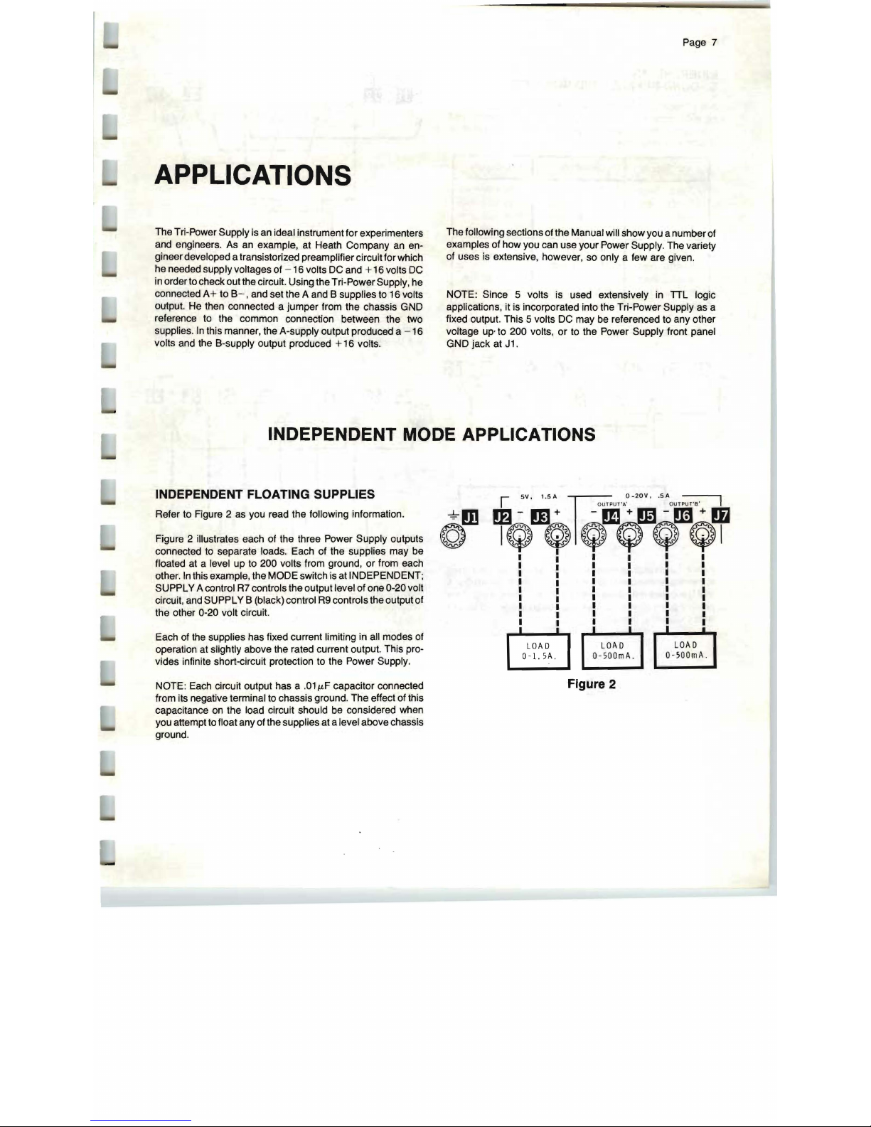
INDEPENDENT FLOATING SUPPLIES
Refer to Figure 2
as
you read the following information.
Figure 2 illustrates each of the three Power Supply outputs
connected
to
separate loads. Each of the supplies may be
floated at a level up to 200 volts from ground, or from each
other.
In
this example, the MODE switch is at INDEPENDENT;
SUPPLY A control
R7
controls the output level of one 0-20 volt
circuit, and SUPPLY B (black) control
R9
controls the output of
the other 0-20 volt circuit.
Each of the supplies has fixed current Hmiting in all modes of
operation at slightly above the rated current output. This provides infinite short-circuit protection to the Power Supply.
NOTE: Each circuit output has a
.011LF
capacitor connected
from
,it
s negative terminal
to
chassis ground. T
he
effect of this
capacitance on the load circuit should be considered when
you attempt to float any of the supplies at a level above chassis
ground.
@m
+oDbIQvQmQ+
II I I I I
I I I I I I
I I I I I I
I I I I I I
I I I I I I
I I I I I I
I I I I I I
I I I I I I
1
~
:
LOAD
I
LOAD
~
~
0-500mA.
0-500mA .
Figure 2
 Loading...