

Page 1
MANUAL MODE
AUTO
TEST
TEST
Replacement
Motion Sensor
Model P6036
Features
• Turns on lighting when motion is detected.
• Automatically turns lighting off.
• Photocell keeps the lighting off during daylight
hours.
•
LED indicates motion was sensed (day or night).
Requirements
• The Light Control requires 120-volts AC.
• If you want to use Manual Mode, the control must
be wired through a switch.
• Some codes require installation by a qualified
electrician.
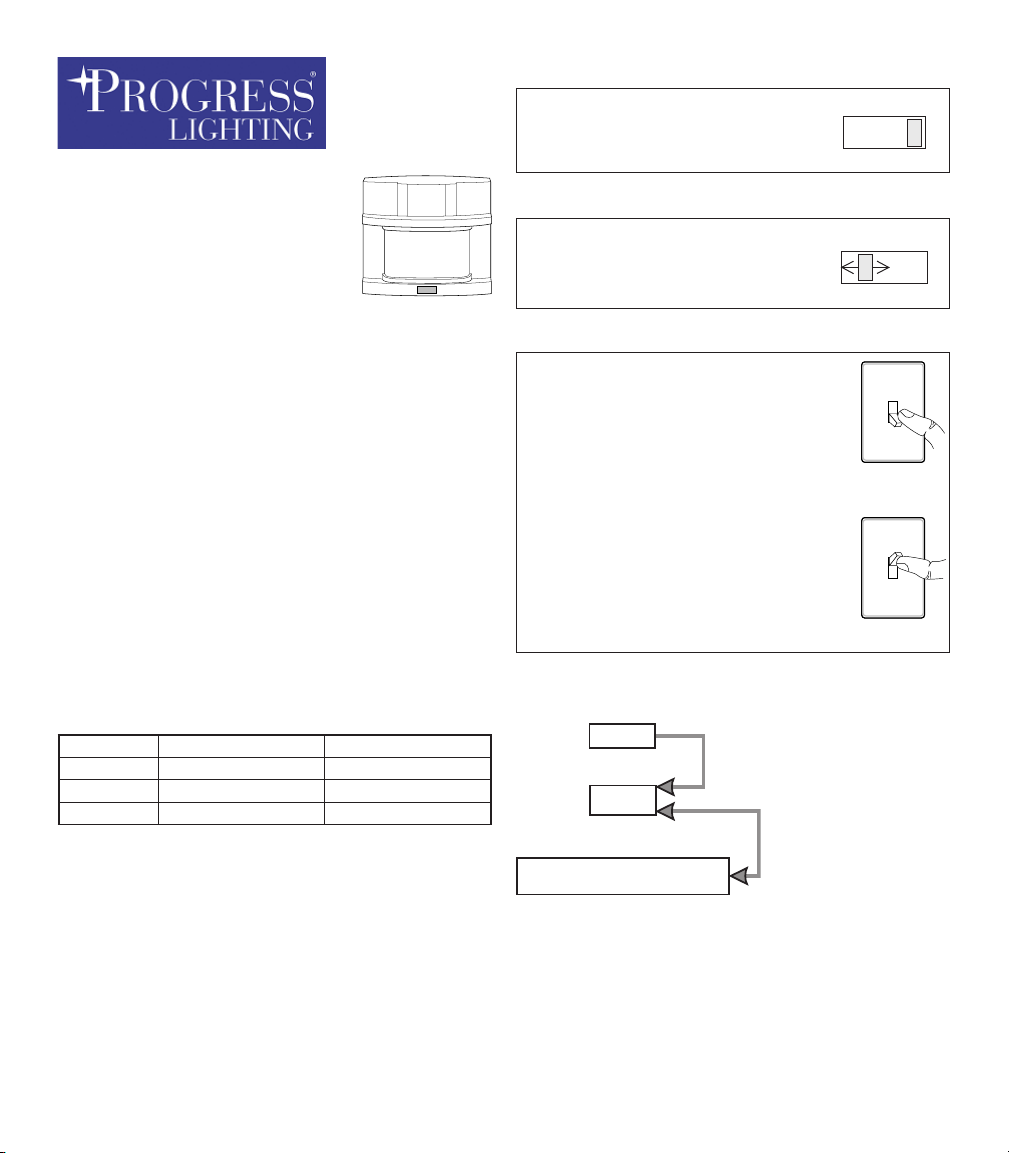
Put the ON-TIME switch on the
bottom of the sensor in the TEST
position.
AUTO
Put the ON-TIME switch in the 1,
5, or 10 minute position.
MANUAL MODE
Manual mode only works at night
because daylight returns the sensor to AUTO.
Flip the light switch off for one
second then back on to toggle
between AUTO and MANUAL
MODE.
Manual mode works only with the
ON-TIME switch in the 1, 5, or 10
position.
ON-TIME
10 5 1 TEST
ON-TIME
10 5 1 TEST
1 Second
OFF
then...
... back on.
OPERATION
Mode: On-Time Works: Day Night
Test
Auto
Manual
* resets to Auto Mode at dawn.
Note: When first turned on wait about 1 1/2 minutes
for the circuitry to calibrate.
5 Seconds x x
1, 5, or 10 Min
To Dawn*
Mode Switching Summary
Move ON-TIME Switch to
1, 5, or 10 minutes
x
x
* If you get confused while switching modes, turn
the power off for one minute, then back on. After
the calibration time the control will be in the AUTO
mode.
Flip light switch
off for one second
then back on*
598-1280-00
Page 2
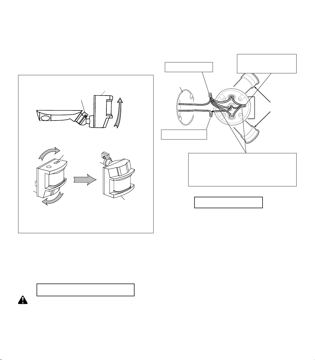
INSTALLATION
For under eave installation, the sensor head
must be rotated as shown in the next two steps
for proper operation and to avoid the risk of electrical shock.
For eave mount only:
❒ Swing the sensor head towards the clamp
screw.
Clamp Screw
Controls
❒ After screwing the sensor into the wall plate,
connect the junction box wires to the Light
Control wires by twisting together and securing
with wire connectors.
Red Sensor Wire to
White to White
Junction
Box
Black Lamp Wire
Lamp Holders
❒ Rotate the sensor head clockwise 180° so
the controls face down.
Controls
Controls
If the sensor pops out of the ball joint, loosen the
clamp screw and push the sensor back into the
ball joint. Tighten the clamp screw when done.
These instructions show the sensor wired to flood
lamps. The white sensor wire is neutral. The black
sensor wire is hot. The red wire is the switched
"hot" wire. The lighting load (500 W, 4.2A max) is
placed across the white and red wires.
Wire the Light ControL
WARNING: Turn power off at the fuse or
circuit breaker.
❒ Remove the existing light fixture, if present.
Black to Black
Optional: Connect additional load
across the white and red wires. Total
lighting load including lampheads on
fixture must not exceed 500W (4.2A).
Mount the Light
❒ Follow the instructions that came with your light fix-
ture for mounting and adjusting the light fixture.
❒ Keep regular PAR-38 lamps at least 1" (25 mm)
from the sensor. Halogen lamps should be kept
at least 2" (51 mm) from the sensor.
-2-
598-1280-00
Page 3

TEST AND ADJUSTMENT
❒ Turn on the circuit breaker and light
switch.
NOTE: Sensor has a 1 1/2 minute calibration
period before it will detect motion. When
first turned on, wait 1 1/2 minutes.
❒ Turn the RANGE control to the mid position and
the ON-TIME control to the TEST position.
ON-TIME
10 5 1 TEST
Bottom of Sensor
Avoid aiming the control at:
• Objects that change temperature rapidly, such
as heating vents and air conditioners. These
heat sources could cause false triggering.
•
Areas where pets or traffic may trigger the control.
• Nearby large, light-colored objects reflecting
light may trigger the shut-off feature. Do not point
other lights at the sensor.
RANGE
MIN MAX
❒ Loosen the clamp screw
in the sensor ball joint and
gently rotate the sensor.
❒ Walk through the cover-
age area noting where
you are when the lights
turn on (also, the LED will
flash several times when
motion is detected). Move
the sensor head up, down,
or sideways to change the
coverage area. Keep the
sensor at least 1" (2.5 cm)
away from the lamps.
❒ Adjust the RANGE as
needed. RANGE set too
high may increase false
triggering.
❒ Secure the sensor head
by tightening the clamp
screw. Do not overtighten the screw.
❒ Set the amount of TIME you want the lights to stay
on after motion is detected (1, 5, or 10 minutes).
Warning - Risk of fire. Do not aim the lamps
at a combustible surface within 3 ft. (1 m).
Aim Sensor
Down for Short
Coverage
Aim Sensor
Higher for Long
Coverage
Clamp
Screw
Ball
Joint
8 ft.
(2.4m)
70 ft.
(21m)
180°
Maximum Range Maximum
Coverage Angle
The sensor is less sensitive to motion directly towards
it, most sensitive to motion across its field of view.
Motion
Sensor
Motion
Least Sensitive Most Sensitive
598-1280-00
SPECIFICATIONS
Range . . . . . . . . . . . . . . Up to 70 ft. (21 m) [varies with
surrounding temperature].
Sensing Angle . . . . . . . . Up to 180°
Electrical Load . . . . . . . . Up to 500 Watt (4.2A) Maximum
Incandescent [Up to 250 Watt
maximum each lamp holder.]
Power Requirements . . . 120 VAC, 60 Hz
Operating Modes . . . . . . TEST, AUTO, and MANUAL
MODE
Time Delay . . . . . . . . . . 1, 5, 10 minutes
Range . . . . . . . . . . . . . . Adjustable
-3-
Page 4

TROUBLESHOOTING GUIDE
SYMPTOM
Li g h ts wi l l no t
come on.
Lig hts come on
in daylight.
Lig hts come on
for no appa re nt
reason.
POSSIBLE CAUSE
1. Light switch is turned off.
2. Light is loose or burned out.
3. Fuse is blown or circuit breaker is turned
off.
4. Daylight turn-off is in effect (recheck
after dark).
5. Incorrect circuit wiring, if this is a new
installation.
6.
Re-aim the sensor to cover desired area.
1. Light Control may be installed in a
relatively dark location.
2. Light Control is in Test. (Set control
switch to an ON-TIME position).
1. Light Control may be sensing small
animals or automobile traffic (re-aim
sensor).
2. Range is set too high. (Reduce Range).
SYMPTOM
Lights stay on
continuously.
Lights flash on
and off.
POSSIBLE CAUSE
1. A lamp is positioned too close to the sensor or pointed at nearby objects that cause
heat to trigger the sensor. (Reposition the
lamp away from the sensor or nearby
objects).
2. Light Control is pointed toward a heat
source like an air vent, dryer vent, or
brightly-painted heat-reflective surface.
(Reposition sensor).
3. Light Control is in Manual Mode. (Switch
to Auto.)
1. Heat or light from the lamps may be turning
the Light Control on and off. (Reposition
the lamps away from the sensor).
2. Heat being reflected from other objects may
be affecting the sensor. (Reposition sen-
sor).
3. Light Control is in the Test mode and
warming up. (Flashing is normal under
these conditions).
4. Light Control is detecting a light source.
(Reposition Light Control or lamp).
-4-
598-1280-00
 Loading...