

Page 1
This package includes:
• Lantern
• Easy to use Universal Mounting Bracket
• Mounting Hardware
• Wire Connectors
Requirements
• The light control requires 120 volts AC.
• If you want to use Manual Mode, the control
must be wired through a switch.
• Some codes require installation by a
qualified electrician.
Features
• Light comes on when motion is detected.
• Automatically turns light off.
• Dusk Accent lighting.
• Photocell keeps the light off during daylight
hours.
© 2007 HeathCo LLC 598-1207-01
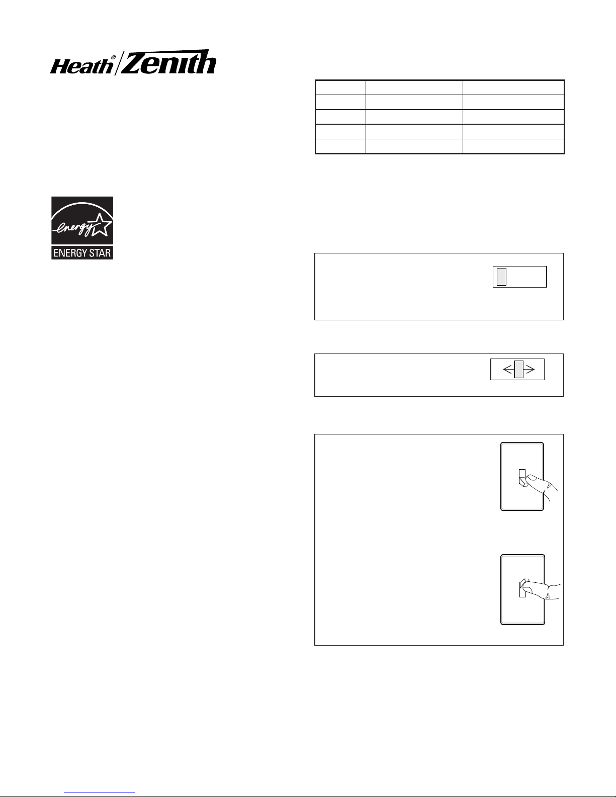
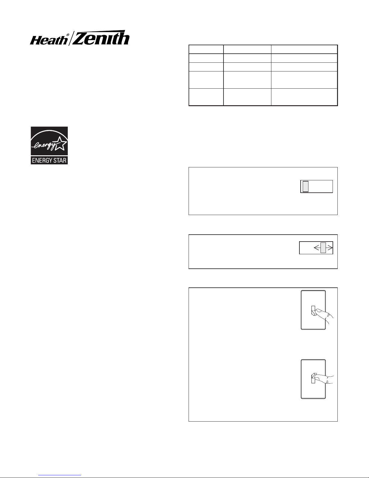
MANUAL MODE
... back on.
1 Second
OFF then...
OPERATION
TEST
TEST 1 5 10 MIN
AUTO
TEST 1 5 10 MIN
DualBrite® Motion
Sensing Coach Light
for Canadian Tire
Set the ON-TIME switch on
the bottom of the cover plate
to TEST and the DualBrite®
switch OFF.
Set ON-TIME switch to
1, 5, or 10 minutes.
Manual mode only works at
night because daylight returns the sensor to AUTO.
Flip the light switch off for
one second then back on to
toggle between AUTO and
MANUAL MODE.
Manual mode works only
with the ON-TIME switch in
the 1, 5, or 10 position.
* resets to Auto Mode at dawn.
Note: When first turned on wait about 1 1/2
minutes for the circuitry to calibrate.
Mode: On-Time Works: Day Night
Test 5 Seconds x x
Auto 1, 5, or 10 Min x
Manual To Dawn* x
Accent 3, 6 Hr, to Dawn x
Meets the ENERGY STAR®
guidelines when Dua lBrite®
function is off.
Page 2
2
598-1207-01
INSTALLATION
For best performance, mount the fixture about
6 feet (1.8 m) above the ground.
ON-TIME Switch at 1,
5, or 10 minutes
Mode Switching Summary
Flip light
switch off for
one second
then back on*
MANUAL MODE
AUTO
TEST
* If you get confused while switching modes,
turn the power off for one minute, then back
on. After the calibration time the control will
be in the AUTO mode.
DualBrite® Dimmer Control
Light comes on half bright for selected time after dusk (Off, 3 hr., 6 hr., until dawn). Selecting
OFF disables this feature. The motion sensing
features will continue to work as described
in this manual. If motion is sensed, the light
turns on full bright for the ON-TIME (1, 5, or
10 minutes) then returns to dim mode.
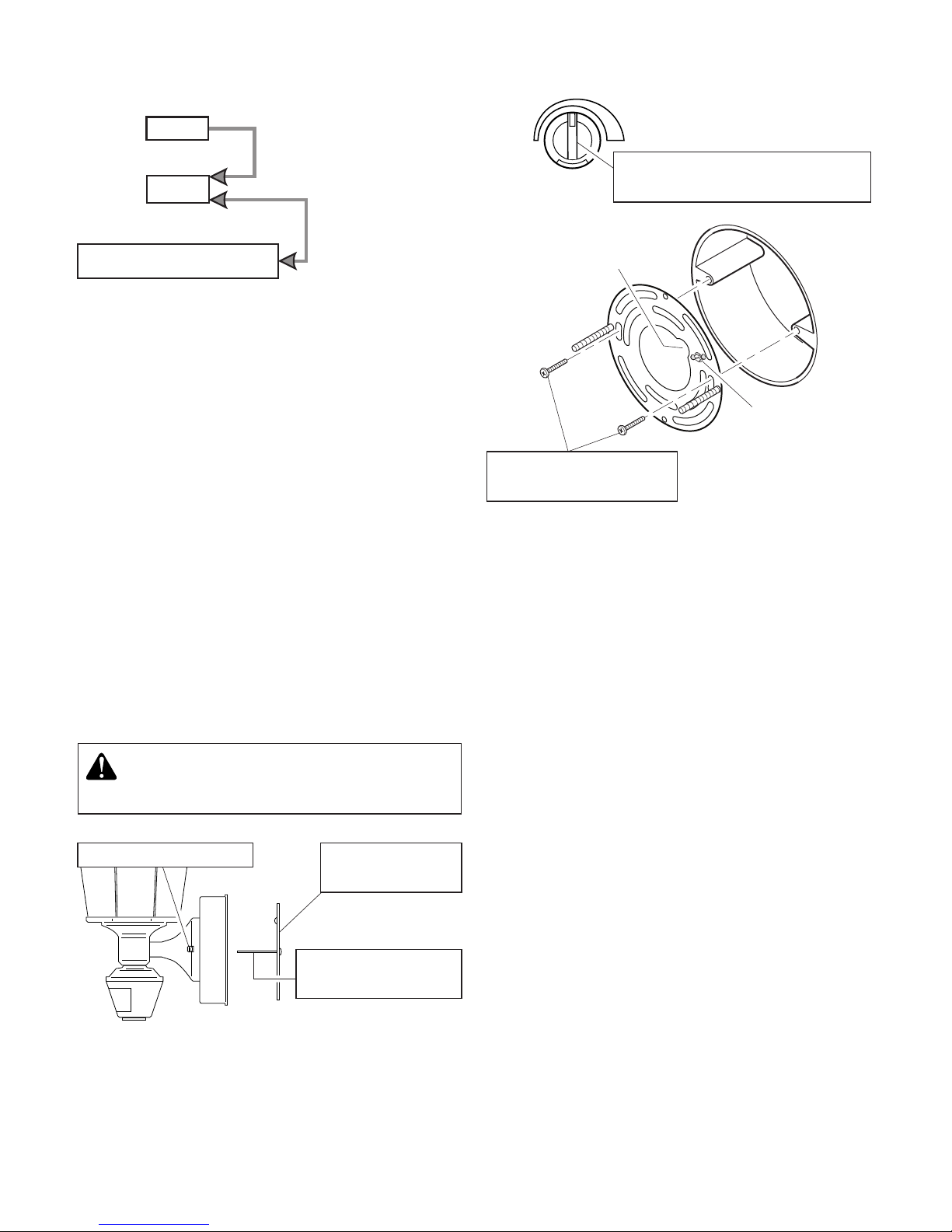
WARNING: Turn power off at circuit
breaker or fuse.
This fixture comes with a universal mounting
bracket. It is pre-assembled on the fixture to
fit the majority of junction box applications.
However, if the slots on the mounting plate
do not line up with the junction box screw
holes:
1. Remove the fixture mounting screws from
the mounting plate. Note: Do not remove
the ground screw.
2. Attach ground wire “pigtail” to ground
screw on mounting plate (See Recom-
mended Grounding Method for additional
information).
3. Flip the mounting plate over.
MAX
SENS
MIN
4. Set sensitivity control on back
of fixture to mid-position.
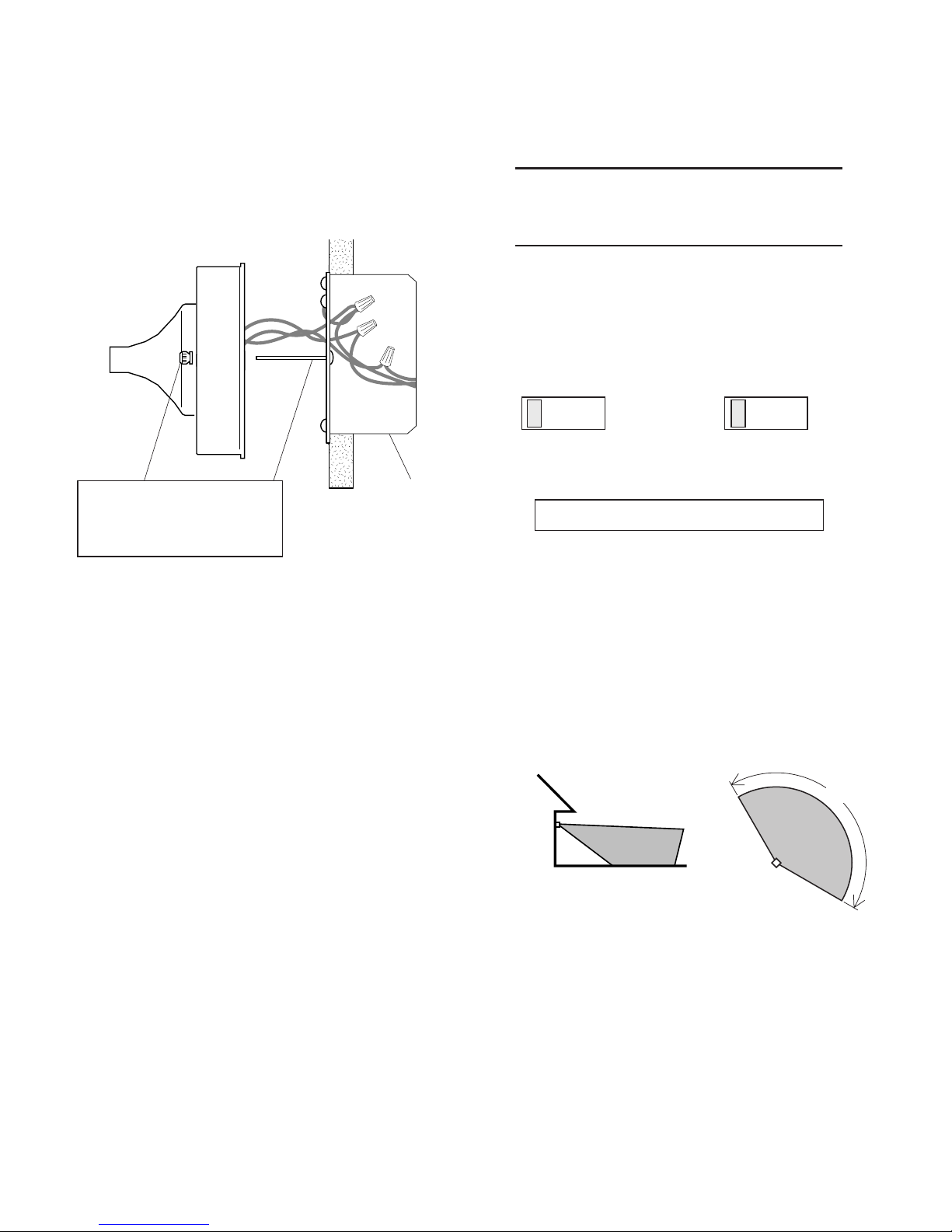
1. Remove two nuts.
5. Attach mounting
plate to junction box.
Wire Path
Ground Screw
3. Tighten screws
finger tight.
2. Remove
Mounting Plate.
Page 3
3
598-1207-01
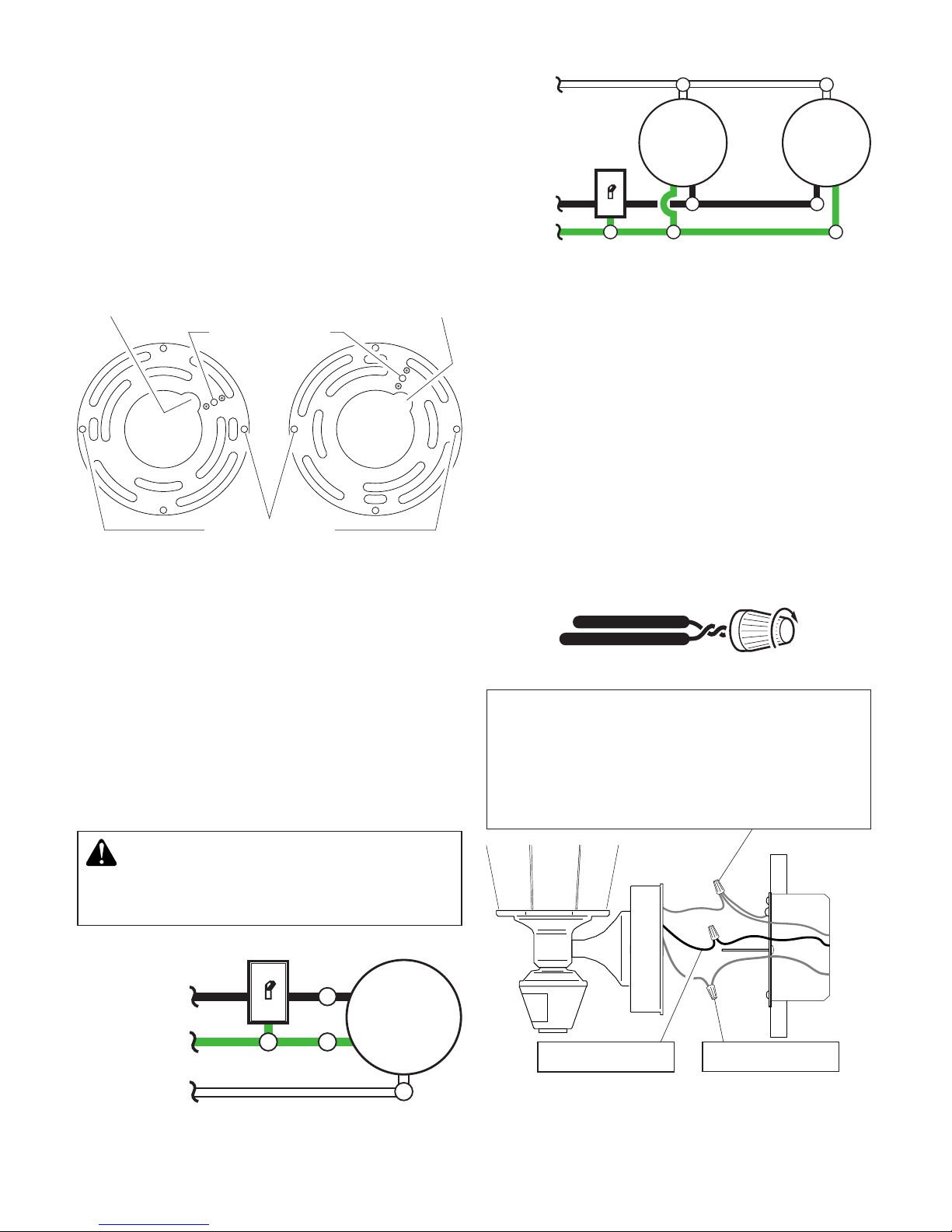
Wire Path
WIRING
One Motion Light
❒ Twist the junction box wires and the
fixture wires together as shown below.
Secure with wire connectors. If you have
a metal junction box, you may not need
the green “pigtail”. If you are unsure about
the grounding method, consult your local
building code.
Two Motion Lights
Black
White
Green
or Bare
Light
Fixture
Black
White
Green
or Bare
Light
Fixture
Light
Fixture
CAUTION: DO NOT connect the RED
wire unless you want to control other
lights from the motion sensor.
Note: All wiring should be run in accordance
with the National Electrical Code through
conduit or another acceptable means.
Contact a qualified electrician if there is
any question as to the suitability of the
system.
Connect the fixture wires to the wires in the
junction box. Twist the wires together and
secure with wire connectors.
Black to black
White to white
Recommended Grounding Method
Use a green ground “pigtail” (not provided) and
twist one end together with the bare fixture wire
and the box ground wire. Secure with a wire
connector. Secure the other end of the “pigtail”
with the GND screw on the mounting plate.
4. Rotate the mounting plate so the wire path
is on the upper right. Note: The wire path
on the mounting plate must be located
as shown below to allow the wires on the
back of the fixture to pass through.
5. Reinstall the fixture mounting screws and
attach the mounting plate to the junction
box as shown.
As Shipped Flipped and
Rotated
Wire Path
Fixture Screws
Ground Screw
Page 4
4
598-1207-01
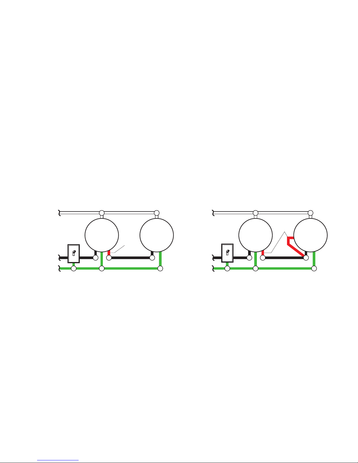
OPTIONAL WIRING
This fixture is provided with a sensor rated for 360 Watts. Since the fixture is only rated 100
Watts, 260 Watts of additional load may be controlled by this sensor.
When determining what a fixture is rated for, do not simply look at the rating on the lamp in
the fixture. Look at the marking which specifies the maximum lamp wattage for which the
fixture is suitable.
Once you have selected the fixtures to be connected and determined their maximum ratings,
add these ratings up. For instance, if you have 3 fixtures rated 100 Watts, 150 Watts, and
75 Watts respectively, you have a total load of 325 Watts.
Wiring Diagram 1 – When wiring to control a standard light fixture: Strip the motion sensor’s
red wire and connect to the standard light’s black wire. Connect all white wires together.
Total fixture ratings must not exceed 360 Watts (3.0 A).
Wiring Diagram 2 – When wiring to control another motion sensing light fixture (Master /
Slave): Strip the red wire in both light fixtures. Connect the red wire of the controlling (master)
fixture to the red and black wires of the controlled (slave) fixture. Connect all white wires
together. Total fixture ratings must not exceed 360 Watts (3.0 A).
Wiring Diagram 1
Black
White
Green
or Bare
Light
Fixture
Light
Fixture
Wiring Diagram 2
(Standard)
Master Slave
Black
White
Green
or Bare
Light
Fixture
Light
Fixture
Red
Red
Page 5
5
598-1207-01
❒ Caulk fixture mounting surface with
silicone weather sealant. You may want
to wait until you have completed the tests
and adjustments on page 6.
❒ Install one 100 W max. light bulb.
Slide the fixture onto the
mounting screws and
tighten nuts.
Junction
Box
COMPLETE THE
INSTALLATION
❒ Stuff the wires into the junction box. Make
sure the wires from the fixture go through
the wire path, and no wires get pinched.
TESTING
❒ Turn on the circuit breaker and light
switch.
30 ft.
(9.1m)
Maximum Range Maximum
Coverage Angle
6 ft.
(1.8 m)
Avoid aiming the control at:
• Pools of water or objects that change
temperature rapidly, such as heating vents
and air conditioners. These heat sources
could cause false triggering.
• Areas where pets or traffic may trigger
the control.
• Nearby large, light-colored objects reflect-
ing daylight may trigger the shut-off feature.
Do not point other lights at the sensor.
Note: Sensor has a 1 1/2 minute warm up pe-
riod before it will detect motion. When
first turned on wait 1 1/2 minutes.
150°
TEST 1 5 10 MIN
ON-TIME
OFF 3 6 DUSK TO
HOUR DAWN
❒ Switch the on-time to TEST position and
DualBrite® switch to the OFF position.
Note: Meets the ENERGY STAR® guidelines
when DualBrite® function is off.
Page 6
6
598-1207-01
❒ If you need to change the sensitivity,
temporarily remove the fixture and make
the adjustment. Too much sensitivity may
increase false triggering.
❒ Set the amount of TIME you want the
light to stay on after motion is detected.
(1, 5, or 10 minutes).
❒ Set the amount of time after dusk you
want the lights on accent level.
240°
Sensor Aiming
Adjustment Angle
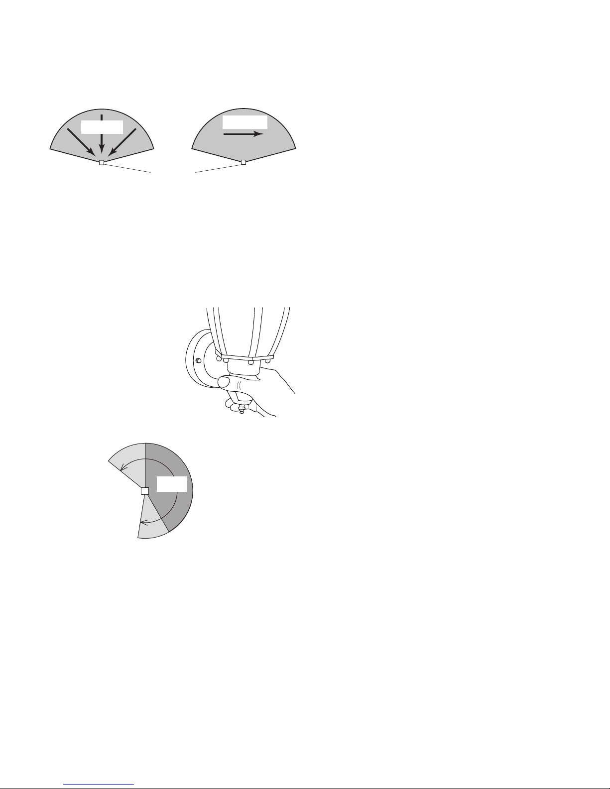
❒ Walk through the coverage area noting
where you are when the lights turn on.
Move the sensor head left or right to
change the coverage area.
Note: Grasp the sensor
only as shown and turn
the entire sensor. Any
other method may
damage the sensor.
Do not force it past
the stops.
Least Sensitive Most Sensitive
The detector is less sensitive to motion directly towards it and more sensitive to across
motion.
Sensor
Motion
Motion
SPECIFICATIONS
Range . . . . . . . . . . . Up to 30 ft. (9.1 m)
[varies with surrounding
temperature]
Sensing Angle . . . . . Up to 150°
Electrical Load . . . . . U p to 1 0 0 Wat t
Maximum Tungsten
Incandescent
Sensor Capacity . . . Up to 360 Watts (3.0 A.)
Maximum Tungsten
Incandescent
Power Requirements 120 VAC, 60 Hz
Operating Modes . . . TEST, AUTO, and
MANUAL MODE
Time Delay . . . . . . . 1, 5, 10 minutes
DualBrite® Timer . . . Off, 3, 6 hours, dusk-to
dawn
HeathCo LLC reserves the right to discontinue
products and to change specifications at
any time without incurring any obligation
to incorporate new features in products
previously sold.
Page 7

7
598-1207-01
TROUBLESHOOTING GUIDE
If you experience a problem with your coach light, follow this guide before returning it to
the retailer.
SYMPTOM
Light stays on
continuously.
Light flashes
on and off.
Light does not
stay on in Manual mode.
POSSIBLE CAUSE
1. The sensor is pointed toward
a heat source like an air vent,
dryer vent, or brightly-painted
heat-reflective surface. (Re-aim
sensor.)
2. Light control is in Manual Mode.
(Switch to Auto.)
3. Light control is in DualBrite®
mode.
4. Sensitivity is set too high. (Re-
duce sensitivity.)
1. Sensor is in the Test mode.
(While in TEST mode, light only
stays on for 5 seconds.)
2. Heat being reflected from other
objects may be affecting the
sensor. (Re-aim sensor.)
1. Nearby large, light-colored
objects reflecting light may
trigger the shut-off feature. Do
not point other lights at the
sensor.
POSSIBLE CAUSE
1. Light switch is turned off.
2. Bulb is loose or burned out.
3. Fuse is blown or circuit breaker
is turned off.
4. Daylight turn-off is in effect
(recheck after dark).
5. Incorrect circuit wiring, if this
is a new installation.
6. Re-aim the sensor to cover
desired area.
1. Light control may be installed
in a relatively dark location.
2. Light control is in Test. (Set
control switch to an ON-TIME
position.)
1. Light control may be sensing
small animals or automobile
traffic (re-aim sensor).
2. Sensitivity is set too high.
(Reduce sensitivity.)
SYMPTOM
Light will not
come on.
Light comes on
in daylight.
Light comes on
for no apparent
reason.
No Service Parts Available for this Product
See your Canadian Tire retailer for warranty information.
Page 8
8
598-1207-01
© 2007 HeathCo LLC 598-1207-01 S
DualBrite® Luces de
Coches Detectores de
Movimiento para
Canadian Tire
Características
• La luz se prende cuando se detecta movimiento.
• Apaga la luz automáticamente.
• La fotocélula mantiene la luz apagada
durante las horas del día.
Este paquete contiene:
• Farol
• Soporte universal de fácil uso
• Ferretería de montaje
• Conectores de alambre
Requisitos
• El control de luz requiere 120 VCA.
• Para usar el Sobrecontrol Manual, conecte
el control con un interruptor.
• Algunos códigos requieren instalación
por un electricista calificado.
Cumple con las normas ENERGY STAR® cuando la función
DualBrite® está apagada.
Ponga el interruptor de tiempo (ON-TIME), al fondo del
detector, en la posición de
prueba (TEST) y DualBrite®
a apagado (OFF).
Modalidad: A tiempo: Trabaja: Día Noche
Prueba
5 seg. x x
Autom.
1, 5 ó 10 min. x
Manual
Hasta el
amanecer*
x
Adorno
3, 6 hrs, hasta
el amanecer
x
FUNCIONAMIENTO
*Se pone en Automático al amanecer.
1 segundo
APAGADO
luego...
El modo manual funciona
sólo por la noche porque la
luz del día pone al detector
en modo AUTOMATICO.
Apague el interruptor por
un segundo y vuélvalo a
prender.
El modo manual funciona
sólo cuando el interruptor
de tiempo (ON-TIME) está
en la posición de 1, 5 ó 10
minutos.
TEST 1 5 10
Ponga el interruptor de tiempo (ON-TIME) en la posición
de 1, 5 ó 10 minutos.
MODO MANUAL
...préndalo.
Nota: Cuando lo prenda por primera vez es-
pere 1 1/2 minutos para que el circuito
se claibre.
TEST 1 5 10
AUTOMATICO
PRUEBA
Page 9

9
598-1207-01
Luz de Adorno (DualBrite®)
La luz se prende con media brillantez por
el tiempo escogido después del atardecer
(apagado, 3 hr., 6 hrs., hasta el amanecer). Si
escoge OFF (APAGADO) deshabilita esta función. Las funciones que detectan movimiento
continuarán funcionando como se describen
en este manual. Si detecta movimiento, la
luz se prende con todo su resplandor por el
tiempo de duración o de ON-TIME (1, 5 ó 10
minutos) y luego regresa a media luz.
Mueva el interruptor de
tiempo (ON-TIME) a 1, 5 ó 10
minutos
Apague el interruptor por
un segundo y préndalo de
nuevo*
PRUEBA
AUTOM.
MODO
MANUAL
* Si se confunde mientras cambia de fases,
apague la electricidad por 1 1/2 minutos y
préndala de nuevo. Después del tiempo
de calibración el control estará en fase
AUTO(MATICA).
Resumen de las modalidades del
interruptor
INSTALACION
Para un mejor funcionamiento, instale el
aparato a casi 1.8 m del suelo.
1. Quite las
dos tuercas.
2. Quite la placa
de montaje.
3. Ajuste los tornillos tan
sólo con los dedos.
ADVERTENCIA: Desconecte la ener-
gía en el disyuntor.
MAX
SENS
MIN
4. Fije de nuevo el alcance de sensibilidad a la posición del medio.
Este aparato viene con un soporte de montaje universal. Está pre-ensamblado en el
aparato para acomodarse a la mayoría de
las aplicaciones de cajas de empalme.
Sin embargo, si las ranuras de la placa de
montaje no se alinean con los agujeros del
tornillo de la caja de empalme:
1. Quite de la placa de montaje los tornillos
de montaje del aparato. Nota: No quite
el tornillo de a tierra.
2. Fije el cable “flexible” al tornillo de a tierra de la placa de montaje (Vea Método
recomendado de conexión a tierra para
más información).
3. Voltee la placa de montaje
Tornillos del
aparato
Paso del alambre
5. Atornille la placa de montaje
a la caja de empalme.
Page 10

10
598-1207-01
Negro a negro
Blanco a blanco
Método recomendado de conexión a tierra
Use un “cable flexible” verde de tierra (no provisto) y tuerza un extremo con el cable desnudo
del aparato y con el cable de a tierra de la caja.
Asegúrelos con un conector de cables. Asegure
el otro extremo del “cable flexible” con el tornillo
de a tierra de la placa de montaje.
Conecte los alambres del aparato a los
alambres de la caja de empalme. Tuerza
juntos los alambres y asegúrelos con
conectores de alambre.
CABLEADO
Luz de un movimiento
❒ Tuerza los cables de la caja de empalme
con los cables del aparato, como se
muestra abajo. Asegúrelos con conectores
de cables. Si tiene una caja de empalme
de metal, no necesita el “cable flexible”.
Si no está seguro del método de conexión
a tierra, consulte con el código local de
construcción.
Luz de dos movimientos
Negro
Blanco
Verde o
Desnudo
Aparato
de Luz
Negro
Blanco
Verde o
Desnudo
CUIDADO: NO conecte el cable ROJO
excepto que desee controlar otras luces
desde el detector de movimiento.
Nota: Todo el cableado debe realizarse de
acuerdo con el Código Eléctrico Nacional
usando tubería ó algún otro medio aceptable.
Póngase en contacto con un electricista
calificado si tiene alguna pregunta
referente a la aptitud del sistema.
Aparato
de Luz
Aparato
de Luz
4.
Voltee la placa de montaje de modo que
el agujero de paso del alambre esté en la
parte derecha superior. Nota: El agujero
de paso del alambre en la placa de montaje debe estar ubicado como se muestra
abajo para que los alambres de la parte
de atrás del aparato puedan pasar.
5. Reinstale los tornillos de montaje del
aparato y fije la placa de montaje a la
caja de empalme como se muestra.
Como se enviaron Placa volteada
y girada
Tornillos del aparato
Tornillo de
tierra
Paso del alambre Paso del alambre
Page 11

11
598-1207-01
CONEXION ALTERNA
Este aparato viene con un detector con una potencia de 360 Vatios. Puesto que el aparato
tiene sólo una potencia de 100 Vatios, la carga adicional de 260 Vatios puede ser controlada
por el detector.
Cuando desee determinar la clasificación de un aparato no vea tan sólo la potencia de la
lámpara. Mire la indicación que especifique el voltaje máximo de la lámpara que el aparato
puede aceptar.
Una vez que ha escogido los aparatos que se conectarán y ha determinado sus máximas
potencias, súmelas. Por ejemplo, si tiene 3 aparatos de 100 , 150 y 75 Vatios respectivamente,
usted tendrá un total de 325 Vatios.
Diagrama de Cableado 1 – Cuando prepare una conexión para controlar un aparato de luz
estándar: Pele el alambre rojo del detector de movimiento y conéctelo al alambre negro de
la luz estándar. Conecte todos los alambres blancos. La capacidad total no debe exceder
los 360 Vatios (3.0 A).
Diagrama de Cableado 2 – Cuando prepare una conexión para controlar otro aparato de
luz detector de movimiento (Maestra / Esclava): Pele el alambre rojo en ambos aparatos de
luz. Conecte el alambre rojo del aparato controlador (maestro) a los alambres rojo y negro
del aparato controlado (esclavo). Conecte todos los alambres blancos. La capacidad total
no debe exceder los 360 Vatios (3.0 A).
Diagrama de Cableado 1
Negro
Blanco
Verde o
Desnudo
Diagrama de Cableado 2
(Estándar)
Maestra Esclava
Rojo
Rojo
Aparato
de Luz
Aparato
de Luz
Negro
Blanco
Verde o
Desnudo
Aparato
de Luz
Aparato
de Luz
Page 12

12
598-1207-01
❒ Calafatee el aparato y la superficie de
montaje con un sellador de silicona contra
la intemperie. Es mejor que espere hasta
que haya completado las pruebas y los
ajustes indicados en la página 13.
❒ Instale una bombilla de 100 Vatios
Máx.
Deslice al apartato sobre
los tornillos de montaje y
ajuste las tuercas.
la caja de
empalme
COMPLETE LA
INSTALACION
❒ Meta los cables en la caja de empalme.
Asegúrese que los cables del aparato
pasen por el paso para los cables y que
no estén pinchados.
PRUEBA
❒ Prenda el cortacircuitos y el interruptor
de luz.
Alcance Máximo Angulo de
Cobertura Máxima
Evite apuntar el control hacia:
• Objetos que cambien rápidamente de tem
-
peratura tales como ductos de calefacción
y acondicionadores de aire. Estas fuentes
de calor pueden causar falsas alarmas.
• Areas donde animales domésticos o el
tráfico puedan activar el control.
• Los objetos grandes cercanos y de
colores resplandecientes que reflejan la
luz del día pueden hacer que el detector
se apague. No apunte otras luces hacia el
detector.
Nota: El detector tiene un período de cerca
de 1
1
/2 minutos de calentamiento antes
de detectar movimiento. Cuando lo
prenda por primera vez, espere 1 1/2
minutos.
9.1m
1.8 m
150°
TEST 1 5 10 MIN
ON-TIME
OFF 3 6 DUSK TO
HOUR DAWN
❒ Fije el de adorno (DualBrite®) a apagado
(OFF) y el control de ON-TIME a la posición
de prueba (TEST).
Nota: Cumple con las normas ENERGY
STAR® cuando la función DualBrite® está
apagada.
Page 13

13
598-1207-01
❒ Camine por el área de protección dándose
cuenta dónde está cuando la luz se prende. Mueva la cabeza del detector hacia la
izquierda o derecha para cambiar el área
de protección.
Lo menos sensible Lo más sensible
El detector es menos sensible al movimiento
que se dirige directamente hacia él.
Nota: Agarre sólo el detector, como se muestra,
y gire todo el detector.
Cualquier otro método
puede dañarlo. No lo force más allá de los puntos
de parada.
Angulo de Ajuste
de Puntería del
Detector
❒ Fije la sensibilidad (SENS) como necesite.
Demasiada sensibilidad puede aumentar
las falsas alarmas.
❒ Fije el período de tiempo (ON-TIME) que
la luz debe quedarse prendida después de
detectar movimiento (1, 5 ó 10 minutos).
❒ Determine la cantidad de tiempo después
del anocher que usted quiere que la luz
permanezca al nivel de acento.
Detector
Movimiento
Movimiento
240°
ESPECIFICACIONES
Alcance . . . . . . . . . . .Hasta 9.1 m. (varía
con la temperatura
del medio ambiente).
Angulo de detección . Hasta 150°
Carga Eléctrica . . . . . Hasta un máximo de
100 Vatios de tungs-
teno incandescente
Capacidad del
Detector . . . . . . . . . . . Hasta un máximo de
360 Vatios (3,0 A.) de
tungsteno incandes-
cente
Requisitos de
Energía . . . . . . . . . . . 120 VCA, 60 Hz
Fases de
Operación . . . . . . . . . PRUEBA, AUTO-
MATICO y MODO
MANUAL
Retardo de Tiempo . .1, 5, 10 minutos
Temporizador
DualBrite® . . . . . . . . . Apagado, 3, 6 horas,
del atardecer al ama-
necer
HeathCo LLC se reserva el derecho de
descontinuar productos y de cambiar especificaciones a cualquier momento sin incurrir
en ninguna obligación de tener que incorporar nuevas características en los productos
vendidos con anterioridad.
Page 14

14
598-1207-01
GUIA DE INVESTIGACION DE AVERIAS
Si tiene algún problema con la luz del coche, siga las indicaciones de esta guía antes de
devolverlo al minorista.
SINTOMA
La luz se
queda
prendida
continuamente.
La luz se
prende y
se apaga.
La luz no
queda encendida en
el m o d o
manual.
POSIBLE CAUSA
1. El control de luz está apuntando
hacia una fuente de calor tal como
un conducto de aire, de secadora
o hacia una superficie con pintura
brillante y que refleja el calor. (Re-
posicione el detector).
2. El control de luz está en fase
Manual (Cámbiela a Auto).
3. El control de luz está en fase
DualBrite®.
4. La Sensibilidad es demasiado alta.
(Reduzca la sensibilidad).
1. El detector está en la fase Prueba.
(Mientras está en la fase PRUEBA,
la luz sólo queda encendida por 5
segundos).
2. El calor que se refleja de otros objetos
pueden estar afectando al detector.
(Reposicione el detector).
1. Objetos cercanos, grandes y de
colores brillantes que reflejan luz
pueden activar la característica de
apagado. No apunte otras luces
hacia el detector.
SINTOMA
La luz no
se enciende.
La luz se
prende
durante el
día.
La luz se
prende sin
ninguna
razón aparente.
POSIBLE CAUSA
1. El interruptor de luz está apagado.
2. El faro está flojo o fundido.
3. El fusible está quemado o el cortacircuitos está apagado.
4. La desconexión de luz del día
está en efecto. (Compruébelo al
anochecer).
5. Alambrado incorrecto, si ésta es
una nueva instalación.
6. Apunte de nuevo el detector para
cubrir las áreas deseadas.
1. El control de luz puede estar instalado en un lugar relativamente
oscuro.
2. El control de luz está en fase de
Prueba. (Fije el interruptor del con-
trol a la posición de TIEMPO).
1. El control de luz puede estar
detectando animales pequeños o
el trásito de automóviles. (Reposi-
cione el detector).
2. La Sensibilidad es demasiado alta.
(Reduzca la sensibilidad).
No hay piezas de servicio disponibles para este producto
Para información sobre garantía vea a su minorista de Canadian Tire.
Page 15

15
598-1207-01
Caractéristiques
• Allume l’éclairage lorsqu’un mouvement
est détecté.
• Éteint automatiquement l’éclairage.
• Éclairage d'accentuation de crépuscule.
• Photocellule qui maintient l’éclairage éteint
pendant la période de lumière du jour.
Cet emballage contient:
• Lanterne
•
Console de montage universelle facile à utiliser
• Ferrures de montage
• Serre-fils
Exigences
• La commande d'éclairage nécessite une
alimentation 120 volts c.a.
•
Si vous désirez utiliser la priorité manuelle, la commande doit être branchée à un interrupteur.
• Certains codes de bâtiment locaux peu-
vent exiger que l’installation soit faite
par un électricien qualifié.
Lanterne de voiture
D
ualBrite
MD
à détecteur
de mouvement pour
Canadian Tire
© 2007 HeathCo LLC 598-1207-01 F
En fonction :
Mode : Temps en circuit : jour nuit
Essai
5 secondes x x
Auto
1, 5, ou 10 min. x
Manuel
au choix, amanecer* x
Accentuation
3, 6 h jusqu’à l’aurore x
FONCTIONNEMENT
* Revient au mode automatique au lever du soleil.
Placez le commutateur ONTIME au bas du couvercle
en position TEST et
l’interrupteur DualBriteMD
en position OFF.
Note: Après mise en circuit, attendre enfiron
1 1/2 minute pour que l’étalonnage du
circuit soit complété.
ESSAI
AUTOMATIQUE
Amener l’interrupteur de
temps en circuit (ON-TIME)
à la position correspondant
à 1, 5 ou 10 minutes.
TEST 1 5 10 MIN
TEST 1 5 10 MIN
Le mode manuel ne fonctionne que la nuit parce que
la lumière du jour remet le
capteur en mode AUTO.
Mettre l’interrupteur hors
circuit pendant une seconde,
plus en circuit pour alterner
entre les modes AUTO et
MANUEL.
Le mode manuel ne fonctionne que lorsque l’interrupteur
ON-TIME est aux positions
1, 5 ou 10.
hors circuit
pendant 1
seconde,
puis ...
... à nouveau
en circuit
PRIORITÉ MANUELLE
Conforme aux exigences
ENERGY STARMD lorsque la
fonction DualBriteMD est désactivée.
Page 16

16
598-1207-01
MINUTERIE DualBrite
MD
La lumière s'allume à mi-intensité pour le
temps choisi après le crépuscule [Off (hors
circuit) 3h, 6h, jusqu'à l'aurore]. Pour désactiver cette fonction, placez le commutateur à
OFF. La fonction de détection de mouvement
continuera toutefois de fonctionner tel que
décrit dans ce guide. Si un mouvement est
détecté, la lumière s'allume à pleine intensité pour le temps (ON-TIME) choisi (1, 5
ou 10 minutes), puis revient en mode faible
intensité.
PRIORITÉ MANUELLE
AUTO
TEST
* Si vous ne savez plus dans quel mode
se trouve l’appareil, couper l’alimentation
pendant une minute puis la rétablir. Après le
temps d’étalonnage, la commande reviendra
au mode AUTO.
Placer l’interrupteur ON-
TIME à 1, 5 ou 10 minutes
Mettre l’interrupteur
hors circuit pendant
une seconde, puis le
remettre en circuit*
Résumé du mode de commutation
1. Enlever les
deux écrous.
2. Enlever la plaque
de montage.
3. Resserrez les vis avec les doigts.
INSTALLATION
Pour un rendement optimal, montez le luminaire à environ 1,8 m au-dessus du sol.
MISE EN GARDE : Coupez l’alimen-
tation au disjoncteur ou au fusible.
MAX
SENS
MIN
4. Réglez la sensibilité
à mi-position à l'arrière
du luminaire.
Ce luminaire vous est fourni avec un support
universel; déjà fixé au luminaire, ce support
convient à la majorité des boîtes de raccordement électrique.
Toutefois, si les rainures de la plaque de
montage ne correspondent pas aux trous
des vis de la boîte :
1. Retirez les vis de fixation au luminaire de
la plaque de montage. Note : Ne retirez
pas la vis de mise à la terre.
2. Fixez la « rallonge » du fil de terre à la
vise de mise à la terre de la plaque de
montage (consultez la section Méthode
de mise à la terre recommandée pour
plus de détails).
3. Retournez la plaque de montage.
4. Faites tourner la plaque de montage de
sorte que l’orifice de passage des fils se
trouve dans le coin supérieur droit. Note :
L’orifice de passage des fils de la plaque
de montage doit être placé comme illustré
ci-dessous pour permettre le passage
des fils à l’arrière du luminaire.
Passage des fils
Vis de la boîte
de jonction
5. Fixer la plaque de montage
à la boîte de jonction.
Page 17

17
598-1207-01
Noir à noir Blanc à blanc
CÂBLAGE
Méthode de mise à la terre recommandée
Utilisez une «queue de cochon» verte (non
fournie) et torsadez-en une extrémité avec
le fil nu du luminaire et le fil de terre de la
boîte de jonction. Utilisez un serre-fils. Fixez
l'autre extrémité de la «queue de cochon»
avec la vis de terre (GND) sur la plaque
de montage.
AVERTISSEMENT: NE PAS raccorder le fil ROUGE à moins que vous ne
vouliez commander d’autres luminaires
au moyen du détecteur de mouvement.
Note :
Tous les fils doivent être installés
dans un conduit ou un autre dispositif acceptable, conformément au Code national
de l’électricité. Contactez un électricien
qualifié pour toute question relative à la
pertinence de l’installation.
Branchez les fils du luminaire aux fils dans
la boîte de raccordement. Torsadez ces fils
ensemble, puis ajoutez-y un connecteur de
fils.
Une lanterne à détecteur de mouvement
Deux lanternes à détecteur de mouvement
Noir
Blanc
Vert ou
dénudé
Luminaire
Noir
Blanc
Vert ou
dénudé
❒ Torsadez ensemble les fils de la boîte
de jonction et ceux du luminaire comme
indiqué ci-dessous. Utilisez des serre-fils.
Si la boîte de jonction est en métal, vous
pourriez nécessiter une «queue de cochon» verte. Si vous avez des doutes sur
la méthode de mise à la terre, consultez
votre code du bâtiment.
LuminaireLuminaire
5. Remettez en place les vis de fixation au
luminaire et la vis de mise à la terre, puis
fixez la plaque de montage à la boîte de
raccordement, comme illustré.
Tel qu’expédié Plaque retournée,
après rotation
Vis de fixation
au luminaire
Vis de mise
à la terre
Passage des fils Passage des fils
Page 18

18
598-1207-01
Diagramme de câblage 1
Noir
Blanc
Vert ou
dénudé
Diagramme de câblage 2
(Standard)
Maître Satellite
Noir
Blanc
CÂBLAGE FACULTATIF
Ce luminaire est pourvu d'un capteur de 360 W. Puisque le luminaire a une intensité de
seulement 100 W, un luminaire additionnel de 260 W peut être contrôlé par ce capteur.
Lorsque vous déterminez l'intensité que peut supporter un luminaire, ne vous contentez
pas de simplement lire l'intensité indiquée sur l'ampoule. Recherchez l'étiquette indiquant
le wattage d'ampoule maximal de l'appareil.
Une fois que vous avez choisi les luminaires à raccorder et déterminé leur intensité maximale
respective, additionnez les intensités. Par exemple, si vous avex 3 appareils dont l'intensité
est 100 Watts, 150 Watts et 75 Watts respectivement, la charge totale est 325 Watts.
Diagramme de câblage 1 – Câblage d’un luminaire standard : Dénudez le fil rouge du
détecteur de mouvement et raccordez-le au fil noir du luminaire standard. Branchez tous
les fils blancs ensemble. L'intensité maximale ne doit pas dépasser 360 Watts (3,0 A).
Diagramme de câblage 2 – Câblage d’un autre luminaire à détecteur de mouvement
(Maître / Satellite) : Dénudez le fil rouge des deux luminaires. Branchez le fil rouge du
luminaire de commande (maître) aux fils rouge et noir du luminaire commandé (satellite).
Branchez tous les fils blancs ensemble. L'intensité maximale ne doit pas dépasser 360
Watts (3,0 A).
Rouge
Rouge
Luminaire Luminaire
Vert ou
dénudé
Luminaire Luminaire
Page 19

19
598-1207-01
COMPLÉTEZ
L'INSTALLATION
❒ S’assurer que les fils du luminaire suivent
le passage des fils et qu’aucun d’eux ne
soit pincé.
Glissez le luminaire sur
les vis de montage et
resserrez les vis.
Boîte de
jonction
❒ Calfeutrer la surface de montage du lu-
minaire avec un scellant silicone résistant
aux intempéries. Vous pouvez attendre
d’avoir terminé les essais et les réglages
de la page 22.
❒ Installez une ampoule de 100 W maxi-
mum.
ESSAIS
❒ Mettre en circuit le disjoncteur et l’in-
terrupteur d’éclairage.
Éviter de pointer l’appareil:
• Sur des flaques d’eau ou des objets dont
la température change rapidement. Ces
sources peuvent causer des déclenchements intempestifs.
• Vers des zones où des animaux ou la
circulation risquent de déclencher l’appareil.
• Sur des objets avoisinants de grande
dimension et de couleur claire. La réflexion pourrait déclencher la fonction de
mise hors circuit à la lumière du jour. Ne
pas pointer d’autres sources lumineuses
sur la commande d’éclairage.
Portée maximale Angle de
couverture maximale
9,1 m
1,8 m
150°
Note : Le capteur doit se réchauffer 1 1/2
minute avant de pouvoir détecter le mouvement. Lorsque l’appareil est mis en
circuit, attendre 1 1/2 minute.
TEST 1 5 10 MIN
ON-TIME
OFF 3 6 DUSK TO
HOUR DAWN
❒ Mettez l’interrupteur de temps en circuit
à la position TEST et l’interrupteur Dual-
BriteMD à la position OFF.
Note : Conforme aux exigences ENERGY
STARMD lorsque la fonction DualBriteMD est
désactivée.
Page 20

20
598-1207-01
❒ Marcher dans la zone de couverture et
noter à quel endroit l’éclairage se déclenche. Déplacer la tête du détecteur vers la
gauche, le droit ou le côté pour modifier
la zone de couverture.
Angle de réglage
du détecteur
❒ Régler la sensibilité (SENSITIVITY) selon
les besoins. Une trop grande sensibilité
pourrait causer des déclenchements intempestifs.
❒ Réglez, à votre goût, le TEMPS de fonc-
tionnement du luminaire après détection
du mouvement (1, 5 ou 10 minutes).
❒ Réglez le temps après le crépuscule où
vous voulez que l’éclairage d’accentuation
s’allume.
Le moins sensible Le plus sensible
Le détecteur est moins sensible au mouvement dans sa direction.
Note: Saisir le détecteur
seulement de la façon
indiquée et tourner tout
l’ensemble. Toute autre
façon de faire pourrait
endommager le détecteur. Ne pas le forcer
au-delà des butées.
Détecteur
Mouvement
240°
Mouvement
FICHE TECHNIQUE
Portée . . . . . . . . . . . . Jusqu’à 9,1 m (varie
selon la température
environnante)
Angle de détection . . . Jusqu’à 150°
Charge électrique . . . Jusqu’à 100 W maxi-
mum Tungstène à
incandescence
Capacité du capteur . Jusqu’à 360 W (3,0 A)
maximum Tungstène
à incandescence
Courant requis . . . . . 120 V c.a., 60 Hz.
Modes de
fonctionnement . . . . . Essai, automatique et
priorité manuelle
Minuterie . . . . . . . . . .1, 5 ou 10 minutes
DualBriteMD . . . . . . . . Fermé, 3, 6 heures,
crépuscule-aurore
HeathCo LLC se réserve le doit d’abandonner
tout produit et d’en changer les spécifications,
en tout temps et sans contracter quelque
obligation que ce soit quant à l’incorporation
de nouvelles caractéristiques aux produits
déjà vendus.
Page 21

21
598-1207-01
CAUSE POSSIBLE
1. Le détecteur de la commande
d’éclairage pointe vers une
source de chaleur comme
un évent d’aération, un
évent de sécheuse ou une
surface peinte de couleur
vive réfléchissant la chaleur.
(Réorienter le détecteur).
2. La commande d’éclairage est
en mode Manuel (faites-la
passer au mode Auto).
3. La commande d’éclairage est
en mode DualBriteMD.
4. Le réglage de portée est trop
élevé. (Réduisez la portée).
1. Le capteur est en mode TEST.
(En mode TEST, l’éclairage
demeure allumé seulement
pendant 5 secondes.)
2.
La chaleur qui est réfléchie par
d’autres objets peut affecter la
commande d’éclairage. (Réo-
rienter le détecteur).
1. Un grand objet de couleur
pâle se trouve à proximité
et reflète la lumière, ce qui
déclenche la fonction d’arrêt.
Évitez de diriger d’autres
lumières sur le capteur.
SYMPTÔME
La lampe reste
allumées continuellement.
La lampe clignote.
L’éclairage ne
demeure pas allumé en mode
Manuel.
CAUSE POSSIBLE
1. L’interrupteur d’éclairage est en
position hors circuit.
2. L’ampoule au quartz est desserrée ou grillée.
3. Le fusible du circuit a sauté ou le
disjoncteur est en position hors
circuit.
4. La fonction de mise hors circuit
à la lumière du jour est engagée.
(Revérifier quand il fait nuit).
5. Mauvais câblage, s’il s’agit d’une
nouvelle installation.
6. Mauvaise orientation. (Réorien-
ter le détecteur pour obtenir la
couverture désirée).
1. La commande d’éclairage est
installée dans un endroit relativement sombre.
2. La commande d’éclairage est
en mode essai. (Placer l’inter-
rupteur ON-TIME à 1, 5 ou 10
minutes.)
1. La commande d’éclairage peut
détecter de petits animaux, des
arbres agités par le vent ou la
circulation automobile. (Réorien-
ter le détecteur).
2. Le réglage de portée est trop
élevé. (Réduisez la portée).
SYMPTÔME
La lampe ne
s’allume pas.
La lampe
s’allume le
jour.
La lampe
s’allume
sans raison
apparente.
GUIDE DE DÉPANNAGE
Si vous avez connu un problème avec votre lanterne cochère, consultez ce guide avant
de retourner le produit chez le détaillant.
Aucune pièce de rechange n’est disponible pour ce produit
Pour informations sur la garantie, consulter votre détaillant Canadian Tire.
Page 22

22
598-1207-01
NOTES / NOTAS _________
_______________________
_______________________
_______________________
_______________________
_______________________
_______________________
_______________________
_______________________
_______________________
_______________________
_______________________
_______________________
_______________________
_______________________
Page 23

23
598-1207-01
NOTES / NOTAS _________
_______________________
_______________________
_______________________
_______________________
_______________________
_______________________
_______________________
_______________________
_______________________
_______________________
_______________________
_______________________
_______________________
_______________________
Page 24

24
598-1207-01
NOTES / NOTAS _________
_______________________
_______________________
_______________________
_______________________
_______________________
_______________________
_______________________
_______________________
_______________________
_______________________
_______________________
_______________________
_______________________
_______________________
 Loading...