

Page 1
Motion Sensor Light
MANUAL MODE
AUTO
TEST
Control
As an ENERGY STAR® Partner, Heath®/Zenith
has determined that this product meets the ENERGY STAR® guidelines for energy efficiency.
This product is ENERGY STAR® compliant
when used with 120 Watt bulbs.
Models 5408 / 5410
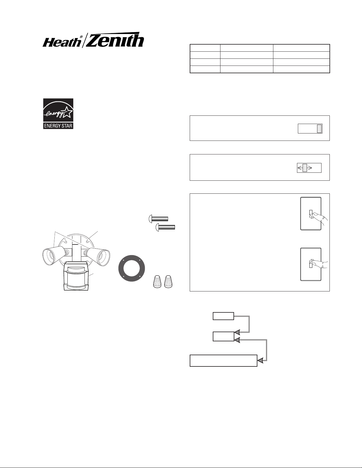
OPERATION
Mode: On-Time Works: Day Night
Test
Auto
Manual
Note: When first turned on wait about 1 1/2 minutes for
the circuitry to calibrate.
Put the ON-TIME switch on the bottom
of the sensor in the TEST position.
5 Seconds x x
1, 5, or 10 Min x
Until Dawn* x
* resets to Auto Mode at dawn.
TEST
ON-TIME
10 5 1 TEST
AUTO
Features
• Turns on lighting when motion is detected.
• Automatically turns lighting off.
•
Photocell keeps the lighting off during daylight hours.
• 5410 models have Flash Alert feature (light flashes on
then off twice before turning on full brightness).
This package includes:
Lamp Holders
Light Control
Cover
Plate
Sensor
4 Mounting
Screws (2 sizes)
Gasket
2 Wire
Connectors
Requirements
• The light control requires 120-volts AC.
• If you want to use Manual Mode, the control must be
wired through a switch.
• Some codes require installation by a qualified
electrician.
• This product is intended for use with a junction box
marked for use in wet locations.
• The backplate has knockouts so the sensor can be
mounted on most junction boxes.
• In some applications a universal adaptor plate may
be needed. Adaptors are available at home centers
and electrical supply stores.
Put the ON-TIME switch in the 1, 5,
or 10 minute position.
MANUAL MODE
Manual mode only works at night
because daylight returns the sensor
to AUTO.
Flip the light switch off for one second
then back on to toggle between AUTO
and MANUAL MODE.
Manual mode works only with the
ON-TIME switch in the 1, 5, or 10
position.
ON-TIME
10 5 1 TEST
1 Second
OFF then...
... back on.
Mode Switching Summary
Move ON-TIME Switch to
1, 5, or 10 minutes
Flip light switch off
for one second then
back on*
* If you get confused while switching modes, turn the
power off for one minute, then back on. After the calibration time the control will be in the AUTO mode.
© 2007 HeathCo LLC 598-1303-01
Page 2
INSTALLATION
For easy installation, select an existing light operated
by a wall switch for replacement.
For best performance, mount the fixture about 8
feet (2.4 m) above the ground. NOTE:
mounted higher than 8 ft. (2.4 m), aiming the sensor down will reduce coverage distance.
❒ Drill the holes needed
to mount the backplate
to the junction box.
If fixture is
Wire the Light ControL
WARNING: Turn power off at circuit breaker
or fuse.
❒ Remove the existing light fixture.
❒ Route the light control's wires through the large
gasket hole.
❒ Connect the junction box wires to the light control
wires. Twist together and secure with a wire
connector.
NOTICE: 5410 models with Flash Alert feature will
also have a wire loop which can be used to disable
the flash alert feature. This wire loop should not
be connected to any other wire.
Black to Black
White to White
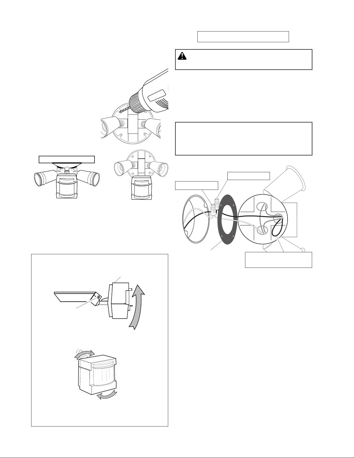
Wall MountEave Mount
For under eave installation, the sensor head must
be rotated as shown in the next two steps for proper
operation and to avoid the risk of electrical shock.
For eave mount only:
❒ Rotate the sensor head towards the clamp screw
joint.
Control Switch
Joint Clamp
❒ Then rotate the sensor head clockwise 180° so the
controls face down.
Gasket
Flash Alert - Activated
(Blue)
If the sensor pops out of the ball joint, loosen the
clamp screw and push the sensor back into the ball
joint. Tighten the clamp screw when done.
2
598-1303-01
Page 3
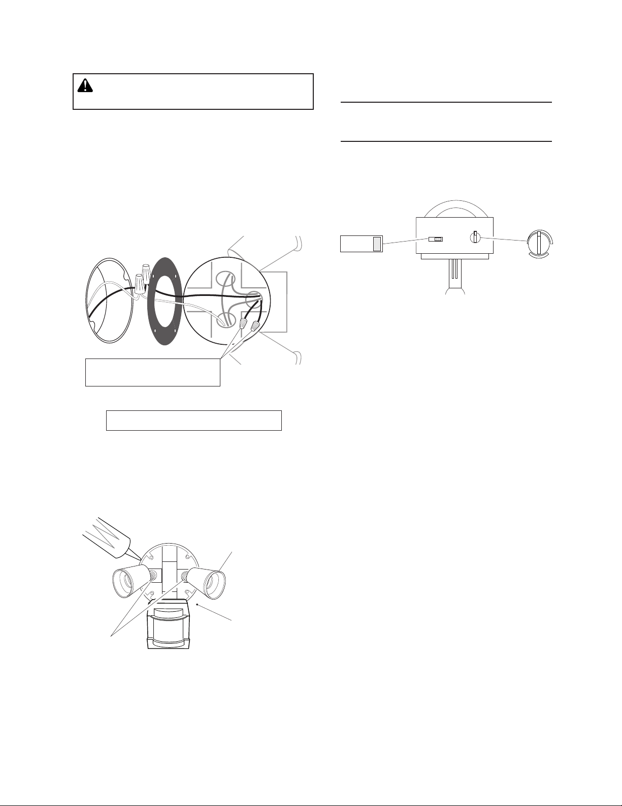
To Deactivate the Flash Alert
TEST AND ADJUSTMENT
WARNING: Turn power off at circuit breaker
or fuse.
❒ Remove the light fixture if necessary.
❒ Locate the (Blue) wire loop coming from the sensor
inside the canopy.
❒ Cut the (Blue) wire loop.
❒ Securely attach wire nuts (supplied) to each of the
cut ends of the (Blue) wire. DO NOT connect the
wires together.
❒ Mount light control to wall or eave.
Flash Alert - Deactivated
(Blue)
❒ Turn on the circuit breaker and light switch.
NOTE: Sensor has a 1 1/2 minute warm up period
before it will detect motion. When first turned
on, wait 1 1/2 minutes.
❒
Turn the SENSITIVITY (SENS) control to the mid position and the ON-TIME control to the TEST position.
ON-TIME
10 5 1 TEST
SENS
MIN MAX
Bottom of Sensor
Mount the Light ControL
❒ Align the light control cover plate and the junction
box holes. Secure with the mounting screws.
❒ If not installed on a weatherproof box or if an adaptor
plate (not included) was used, caulk the wall plate
and mounting surface with silicone.
Avoid water damage and
electrical shock - keep lamp
holders below horizontal.
Keep lamps at
least 1" (25 mm)
Lock nuts
❒ Adjust the lamp holders by loosening the lock nuts
but do not rotate the lamp holders more than 180°
from the factory setting. When screwing in the floodlamps, do not overtighten.
from the sensor.
598-1303-01
3
Page 4
Avoid aiming the control at:
• Objects that change temperature rapidly, such as
heating vents and air conditioners. These heat
sources could cause false triggering.
• Areas where pets or unwanted traffic may trigger
the control.
• Nearby large, light-colored objects reflecting light
may trigger the shut-off feature. Do not point other
lights at the sensor.
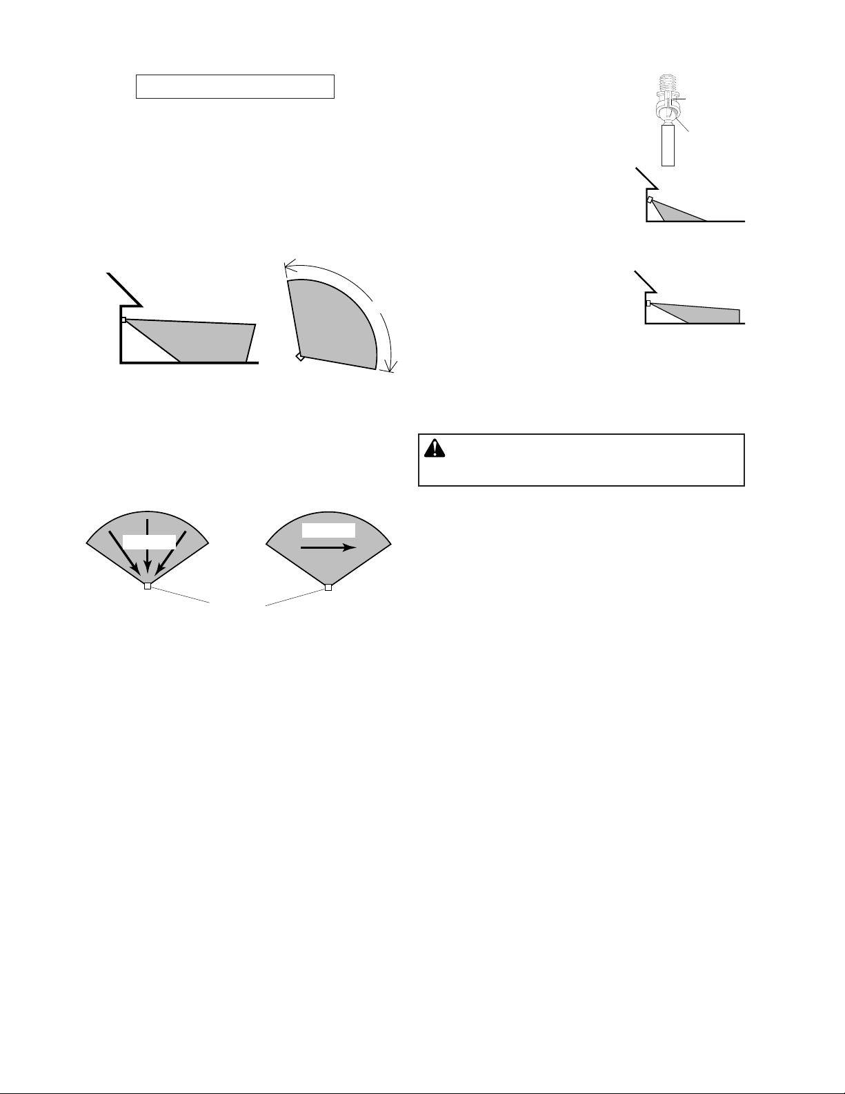
8 ft.
(2.4 m)
60 ft.
(18.3 m)
110°
Maximum Range Maximum
Coverage Angle
The detector is most sensitive to motion across its field
of view.
❒ Loosen the clamp screw in the
sensor ball joint and gently
rotate the sensor.
❒ Walk through the coverage
area noting where you are
when the lights turn on. Move
the sensor head up, down, or
sideways to change the coverage area. Keep the sensor at
least 1" (2.5 cm) away from
the lamps.
❒ Adjust the SENSITIVITY as
needed. Too much sensitivity
may increase false triggering.
❒ Secure the sensor head by
tightening the clamp screw.
Do not overtighten the screw.
❒ Set the amount of TIME you
want the lights to stay on after motion is detected
(1, 5, or 10 minutes).
WARNING - Risk of fire. Do not aim the lamps
at a combustible surface within 3 ft. (1 m).
Down for Short
Higher for Long
Clamp
Screw
Ball
Joint
Aim Sensor
Coverage
Aim Sensor
Coverage
Motion
Motion
Sensor
Least Sensitive Most Sensitive
NOTE:
the sensor down will reduce coverage distance.
If fixture is mounted higher than 8 ft. (2.4 m), aiming
SPECIFICATIONS
Range . . . . . . . . . . . . Up to 60 ft. (18.3 m) [varies with
surrounding temperature].
Sensing Angle . . . . . . Up to 110°
Electrical Load . . . . . . Up to 300 Watt Maximum In-
candescent [Up to 150 Watt
maximum each lamp holder.]
Power Requirements . 120 VAC, 60 Hz
Operating Modes . . . . TEST, AUTO and MANUAL
MODE
Time Delay . . . . . . . . 1, 5, 10 minutes
Range . . . . . . . . . . . . Adjustable
HeathCo LLC reserves the right to discontinue products and to change specifications at any time without
incurring any obligation to incorporate new features
in products previously sold.
4
598-1303-01
Page 5
TROUBLESHOOTING GUIDE
SYMPTOM
Lights will not come
on.
Lig hts com e on
in daylight.
Ligh ts come on
for no apparen t
reason.
POSSIBLE CAUSE
1. Light switch is turned off.
2. F l oo d lig h t is l o ose or
burned out.
3. Fuse is blown or circuit breaker
is turned off.
4. Daylight turn-off is in effect
check after dark).
5. Incorrect circuit wiring, if this is a
new installation.
6. Re-aim the sensor to cover de
sired area.
1. Light control may be installed in
a relatively dark location.
2. L i g h t contro l i s in Tes t .
(Set co n t r o l switch to a n
ON-TIME position).
1. Light control may be sensing
small animals or automobile traffic (re-aim sensor).
2. Sensitivity is set too high.
sensitivity.)
(re-
(Reduce
SYMPTOM
Lights stay on
continuously.
-
Lights flash on
and off.
POSSIBLE CAUSE
1. A flood lamp is positioned too close to
the sensor or pointed at nearby objects
that cause heat to trigger the sensor.
(Reposition the lamp away from the
sensor or nearby objects).
2. Light control is pointed toward a heat
source like an air vent, dryer vent, or
brightly-painted heat-reflective surface. (Reposition sensor).
3. Light control is in Manual Mode.
to Auto.)
1. Heat or light from the lamps may be
turning the light control on and off.
(Reposition the lamps away from the
sensor).
2. Heat being reflected from other objects
may be affecting the sensor. (Reposi-
tion sensor).
3. Light control is in the Test mode and
warming up. (Flashing is normal under
these conditions).
4. Light may be leaking through the flood
lamp reflectors. (Replace the lamps with
new high quality PAR 38 lamps).
5. Light is in Flash Alert mode.
normal operation. See page 3 to deactivate Flash Alert).
(Switch
(This is
-
TECHNICAL SERVICE
Please call 1-800-858-8501 (English speaking only) for assistance before returning
product to store.
If you experience a problem, follow this guide. You may also want to visit our Web site at: www.hzsupport.com.
If the problem persists, call* for assistance at 1-800-858-8501 (English speaking only), 7:30 AM to 4:30 PM CST
(M-F). You may also write* to:
HeathCo LLC
P.O. Box 90004, Bowling Green, KY 42102-9004
ATTN: Technical Service
* If contacting Technical Service, please have the following information available: Model Number, Date of Purchase, and Place of Purchase.
No Service Parts Available for this Product
598-1303-01
5
Page 6

TWO YEAR LIMITED WARRANTY
This is a “Limited Warranty” which gives you specific legal rights. You may also have other rights which vary
from state to state or province to province.
For a period of two years from the date of purchase, any malfunction caused by factory defective parts or
workmanship will be corrected at no charge to you.
Not Covered - Repair service, adjustment and calibration due to misuse, abuse or negligence, light bulbs,
batteries, and other expendable items are not covered by this warranty. Unauthorized service or modification of the product or of any furnished component will void this warranty in its entirety. This warranty does
not include reimbursement for inconvenience, installation, setup time, loss of use, unauthorized service, or
return shipping charges.
This warranty covers only HeathCo LLC assembled products and is not extended to other equipment and
components that a customer uses in conjunction with our products.
THIS WARRANTY IS EXPRESSLY IN LIEU OF ALL OTHER WARRANTIES, EXPRESS OR IMPLIED,
INCLUDING ANY WARRANTY, REPRESENTATION OR CONDITION OF MERCHANT ABILITY OR THAT
THE PRODUCTS ARE FIT FOR ANY PARTICULAR PURPOSE OR USE, AND SPECIFICALLY IN LIEU
OF ALL SPECIAL, INDIRECT, INCIDENTAL, OR CONSEQUENTIAL DAMAGES.
REPAIR OR REPLACEMENT SHALL BE THE SOLE REMEDY OF THE CUSTOMER AND THERE SHALL
BE NO LIABILITY ON THE PART OF HEATHCO LLC FOR ANY SPECIAL, INDIRECT, INCIDENTAL, OR
CONSEQUENTIAL DAMAGES, INCLUDING BUT NOT LIMITED TO ANY LOSS OF BUSINESS OR PROFITS, WHETHER OR NOT FORESEEABLE. Some states or provinces do not allow the exclusion or limitation
of incidental or consequential damages, so the above limitation or exclusion may not apply to you. Please
keep your dated sales receipt, it is required for all warranty requests.
6
598-1303-01
Page 7

Detector de
PRUEBA
AUTOM.
MODO
MANUAL
Movimiento y
FUNCIONAMIENTO
Modalidad: A tiempo: Trabaja: Día Noche
Prueba
Autom.
Manual
*Se pone en Automático al amanecer.
5 seg. x x
1, 5 ó 10 min. x
Hasta el
amanecer*
x
Control de Luz
Como socio de ENERGY STAR®, Heath®/Zenith ha determinado que este producto cumple
con las pautas de ENERGY STAR® con respecto a eficiencia de energía. Este producto
está en conformidad con ENERGY STAR®
cuando se usa con focos de 120 vatios.
Modelos 5408 / 5410
Características
• Prende la luz cuando detecta movimiento.
• Apaga la luz automáticamente.
•
La fotocélula mantiene la luz apagada durante el día.
•
Los modelos 5410 tienen la característica de Destello
de Alerta (la luz se prende y se apaga por dos veces
antes de prenderse con su brillo completo).
Este paquete tiene:
Porta-lámparas
Placa
Cubertora
4 Tornillos
(2 dimensiones)
Nota: Cuando lo prenda por primera vez espere 1 1/2
minutos para que el circuito se claibre.
Para PRUEBA:
Ponga el interruptor de tiempo (ONTIME), al fondo del detector, en la
posición de prueba (TEST).
Para AUTOMATICO:
Ponga el interruptor de tiempo
(ON-TIME) en la posición de
1, 5 ó 10 minutos.
Para MODO MANUAL:
El modo manual funciona sólo por la
noche porque la luz del día pone al
detector en modo AUTOMATICO.
Apague el interruptor por un segundo y
vuélvalo a prender para conmutar entre
MODO AUTOMATICO y MANUAL.
ON-TIME
10 5 1 TEST
ON-TIME
10 5 1 TEST
1 segundo
APAGADO
luego...
El modo manual funciona sólo con el
interruptor ON-TIME en la posición
Control de Luz
Detector
Empaquetadura
2 Tuercas para
Alambre
1, 5 ó 10.
...préndalo.
Resumen de las modalidades del
interruptor
Requisitos
• El control de luz requiere 120 VCA.
• Para usar el Sobrecontrol Manual, conecte el control
con un interruptor.
• Algunos códigos requieren instalación por un
electricista calificado.
• Este producto debe ser usado con una caja de empalmes marcada para ser usada en lugares mojados.
• La placa trasera tiene discos removibles para poder
montar el detector en casi todas las cajas de empalmes.
• En algunas aplicaciones se puede necesitar una placa
adaptadora. Los adaptadores se pueden comprar
en los Centros Comerciales para el Hogar y en las
Tiendas de Aparatos Eléctricos.
598-1303-01
© 2007 HeathCo LLC 598-1303-01 S
* Si se confunde mientras cambia de fases, apague
la electricidad por un minuto y préndala de nuevo.
Después del tiempo de calibración el control estará
en fase AUTO(MATICA).
7
Mueva el interruptor de tiempo
(ON-TIME) a 1, 5 ó 10 minutos
Apague el interruptor por
un segundo y préndalo de
nuevo*
Page 8

INSTALACION
Para una fácil instalación escoja una luz con un
interruptor de pared.
Para un mejor funcionamiento, instale el aparato a casi
2,4 m del suelo. NOTA: Si el aparato está instalado a
más de 8 pies (2,4 m), si se apunta el detector hacia
abajo se reducirá la distancia de cobertura.
❒ Perfore los agujeros que se nece-
siten para montar la placa de atrás
a la caja de empalmes.
ConeCte eL ControL De Luz
ADVERTENCIA: Desconecte la energía en el
disyuntor.
❒ Quite el aparato de luz existente.
❒ Dirija los alambres de control de luz por el agujero
grande del empaque.
❒ Conecte los alambres de la caja de empalmes con
los alambres del control de luz. Unalos y asegúrelos
con un conector de alambre.
AVISO: Los modelos 5410 con la característica
de Destello de Alerta tendrán también un bucle
de alambre que se puede usar para deshabilitar
la característica de destello de alerta. Este bucle
de alambre no debería estar conectado a ningún
otro alambre.
Negro a negro
Blanco a blanco
Montaje en pared
Para instalarlo bajo el alero, la cabeza del detector
debe ser girada como se muestra en los dos pasos
siguientes para evitar el riesgo de un choque eléctrico.
Sólo para montaje eléctrico:
❒ Gire la cabeza del detector hacia la unión del tornillo
sujetador.
Tornillo Sujetador
❒ Entonces gire la cabeza del detector hacia la
derecha por 180° hasta que los controles miren
hacia abajo.
Montaje en alero
Controles
Empaquetadura
Destello de Alerta –
Activado (Azul)
Si el detector se sale de la unión esférica, afloje el tornillo
sujetador y empuje el detector hacia dentro de la unión
esférica. Apriete el tornillo sujetador cuando termine.
8
598-1303-01
Page 9

Para Desactivar el Destello de Alerta
PRUEBA Y AJUSTE
ADVERTENCIA: Desconecte la energía en el
disyuntor.
❒ Quite el aparato de luz si es necesario.
❒ Ubique el bucle de alambre (Azul) que viene del
detector que está dentro del escudete.
❒ Corte el bucle de alambre (Azul).
❒ Fije con seguridad los conectores de alambre
(provistos) a cada uno de los extremos cortados
del alambre (Azul). NO conecte los alambres.
❒ Instale el control de luz en la pared o en el alero.
Destello de Alerta –
Desactivado (Azul)
❒ Prenda el cortacircuitos y el interruptor de luz.
NOTA: El detector tiene un período de cerca de 1 1/2
minutos de calentamiento antes de detectar
movimiento. Cuando lo prenda por primera
vez, espere 1 1/2 minutos.
❒ Gire el control de sensibilidad (SENS) a la mid, y
el control de tiempo (ON-TIME) a la posición de
prueba (TEST).
ON-TIME
10 5 1 TEST
SENS
MIN MAX
Parte de abajo del detector
instaLe eL ControL De Luz
❒ Alinee la placa cubertora del control de luz y los
agujeros de la caja de empalmes. Asegúrelos con
los tornillos de montaje.
❒ Calafatee la placa de la pared y la superficie
de montaje con un sellador de silicona contra la
intemperie.
Evite el golpe eléctrico y el
dañado causado por el agua
— mantenga los portalámparas
abajo del nivel horizontal.
Mantenga las
lámparas por lo
Contratuercas
❒ Ajuste los portalámparas aflojando las contratuer-
cas, pero no los gire más de 180° de la calibración
hecha en fábrica. Cuando atornille los proyectores
no los ajuste demasiado.
menos a 25 mm
del detector.
598-1303-01
9
Page 10

Evite apuntar el control hacia:
• Objetos que cambien rápidamente de temperatura
tales como ductos de calefacción y acondiciona-
dores de aire. Estas fuentes de calor pueden causar
falsas alarmas.
• Áreas donde las mascotas o el tráfico no deseado
pueden activar el control.
• Los objetos grandes cercanos y de colores res-
plandecientes que reflejan la luz del día pueden
hacer que el detector se apague. No apunte otras
luces hacia el detector.
8 pies
(2.4 m)
60 pies
(18.3 m)
110°
Alcance Máximo Angulo de
Cobertura Máxima
El detector es menos sensible del movimiento que se
dirige hacia él.
Movimiento
Movimiento
❒ Afloje el tornillo sujetador en la
unión esférica y gire despacio
el detector.
❒ Camine por el área a prote-
gerse y dése cuenta dónde
está cuando se prende la luz.
Mueva la cabeza del detector
hacia arriba, hacia abajo o
hacia los lados para cambiar el área de protección.
Mantenga al detector por
lo menos a 1 pulgada (2.5
cm) de las lámparas.
❒ Fije la sensibilidad (SENS)
como necesite. Demasiada
sensibilidad puede aumentar
las falsas alarmas.
❒ Asegure la puntería de la ca-
beza del detector ajustando el
tornillo sujetador. No lo apriete
demasiado.
❒ Fije el período de tiempo (ON-TIME) que la luz debe
quedarse prendida después de detectar movimiento
(1, 5 ó 10 minutos).
ADVERTENCIA - Riesgo de incendio. No apunte
las lámparas a superficies combustibles dentro
de un 3 pies (1 m).
abajo para poca
mayor cobertura
Tornillo
Sujetador
Unión
Esférica
Apunte el
detector hacia
cobertura
Apunte el
detector más
arriba para
Detector
Lo menos sensible Lo más sensible
NOTA: Si el aparato está instalado a más de 8 pies (2,4
m), si se apunta el detector hacia abajo se reducirá la
distancia de cobertura.
ESPECIFICACIONES
Alcance . . . . . . . . . . . . . . . . Hasta 60 pies (18.3 m)
[varía de acuerdo a la tem-
peratura que le rodea]
Ángulo de sensibilidad . . . . . Hasta 110˚
Carga eléctrica . . . . . . . . . . Hasta 300 vatios máximo
de luz incandescente
[hasta 150 vatios máximo
por cada portalámparas].
Requisitos de potencia . . . . 120 V ca, 60 Hz
Modos de operación . . . . . . PRUEBA, AUTOMATICO,
y MODO MANUAL
Retardo de Tiempo . . . . . . . 1, 5, 10 minutos
Alcance . . . . . . . . . . . . . . . . Ajustable
HeathCo LLC se reserva el derecho de descontinuar
productos y de cambiar especificaciones a cualquier
momento sin incurrir en ninguna obligación de tener
que incorporar nuevas características en los productos
vendidos con anterioridad.
10
598-1303-01
Page 11

GUIA DE INVESTIGACION DE AVERIAS
SINTOMA
La luz no se enciende.
La luz se prende
durante el día.
La luz se prende
sin ninguna razón
aparente.
POSIBLE CAUSA
1. El interruptor de luz está apaga
do.
2. El faro está flojo o fundido.
3. El fusible está quemado o el
cortacircuitos está apagado.
4. La desconexión de luz del día está
en efecto. (Compruébelo cuando
comience la obscuridad).
5. Alambrado incorrecto, si ésta es
una nueva instalación.
6. No está apuntando correctamen
te. (Apunte de nuevo el detector
para proteger el área deseada).
1. El control de luz puede estar ins
talado en un lugar relativamente
oscuro.
2. El control de luz está en fase de
Prueba. (Fije el interruptor del con-
trol a la posición de TIEMPO).
1. El control de luz puede estar de
tectando animales pequeños o el
trásito de automóviles. (Reapunte
el detector).
2. La Sensibilidad es demasiado
alta. (Reduzca la sensibilidad).
SINTOMA
-
La luz se
queda
prendida
continuamente.
-
-
La luz se prende y se apaga.
-
POSIBLE CAUSA
1. Un faro está colocado demasiado cerca
al detector o apunta a objetos cercanos
que hace que el calor active el detector.
(Reposicione la lámpara lejos del
detector o de los objetos cercanos).
2. El control de luz está apuntando hacia
una fuente de calor tal como un conducto de aire, de secadora o hacia
una superficie con pintura brillante y
que refleja el calor. (Reposicione el
detector).
3. El control de luz está en la Modo
Manual. (Cámbiela a Automática).
1. El calor o la luz de las lámparas pueden
estar prendiendo y apagando el control
de luz. (Reposicione las lámparas lejos
del detector).
2. El calor que se refleja de otros objetos
puede estar afectando al detector.
(Reposicione el detector).
3. El control de luz está en fase de
Prueba y calentándose. (El prender-
se y apagarse es normal bajo estas
condiciones).
4. La luz puede estar escapándose por los
reflectores del faro. (Cambie los faros con
nuevas lámparas de alta calidad).
5. La luz está en fase de Destello de
Alerta. (Este es el funcionamiento
normal. Vea la página 9 para desactivar
el Destello de Alerta).
SERVICIO TÉCNICO
Favor de llamar al 1-800-858-8501 (sólo para hablar en inglés) para pedir ayuda antes
de devolver el producto a la tienda.
Si tiene algún problema, siga esta guía. Usted puede también visitar nuestro sitio Web: www.hzsupport.com.
Si el problema continúa, llame al 1-800-858-8501 (sólo para hablar en inglés), de 7:30 AM a 4:30 PM CST
(L-V). Usted puede también escribir a:
HeathCo LLC
P.O. Box 90004, Bowling Green, KY 42102-9004
ATTN: Technical Service (Servicio Técnico)
* Si se llama al Servicio Técnico, por favor tener lista la siguiente información: Número de Modelo, Fecha de
compra y Lugar de compra.
No hay piezas de servicio disponibles para este producto.
598-1303-01
11
Page 12

GARANTÍA LIMITADA A 2 AÑOS
Esta es una “Garantía Limitada” que le da a Ud. derechos legales específicos. Usted puede también tener
otros derechos que varían de estado a estado o de provincia a provincia.
Por un período de 2 años desde la fecha de compra, cualquier mal funcionamiento ocasionado por partes
defectuosas de fábrica o mano de obra será corregido sin cargo para Ud.
No cubierto - Servicio de reparación, ajuste y calibración debido al mal uso, abuso o negligencia, bombillas, baterías, u otras partes fungibles no están cubiertas por esta garantía. Los Servicios no autorizados
o modificaciones del producto o de cualquier componente que se provee invalidarán esta garantía en su
totalidad. Esta garantía no incluye reembolso por inconveniencia, instalación, tiempo de instalación, perdida
de uso, servicio no autorizado, o costos de transporte de retorno.
Esta garantía cubre solamente los productos ensamblados por HeathCo LLC y no se extiende a otros equipos o componentes que el consumidor usa junto con nuestros productos.
ESTA GARANTÍA ESTÁ EXPRESAMENTE EN LUGAR DE OTRAS GARANTÍAS, EXPRESADAS O SOBREENTENDIDAS, INCLUYENDO CUALQUIER GARANTÍA, REPRESENTACIÓN O CONDICIÓN DE
COMERCIABILIDAD O QUE LOS PRODUCTOS SE ADAPTEN PARA CUALQUIER PROPÓSITO O USO
EN PARTICULAR, Y ESPECIFICAMENTE EN LUGAR DE TODOS LOS DAÑOS ESPECIALES, INDIRECTOS, INCIDENTALES Y CONSECUENTES.
LA REPARACIÓN O EL REEMPLAZO DEBERÍA SER LA ÚNICA SOLUCIÓN DEL CLIENTE Y NO HABRÁ
RESPONSABILIDAD POR PARTE DE HEATHCO LLC POR CUALQUIER DAÑO ESPECIAL, INDIRECTO,
INCIDENTAL O CONSECUENTE, INCLUIDOS PERO NO LIMITADOS A CUALQUIER PÉRDIDA DE NEGOCIO O GANACIAS SEAN O NO PREVISIBLES. Algunos estados o provincias no permiten la exclusión
o limitación de daños incidentales o consecuentes, de modo que la limitación o exclusión arriba indicada
puede que no se aplique a Ud. Por favor guarde su recibo de venta fechado; se lo requiere para cualquier
solicitud de garantía.
12
598-1303-01
Page 13

Commande
PRIORITÉ MANUELLE
AUTO
TEST
d’éclairage à détecteur
FONCTIONNEMENT
Mode: Temps en circuit : En fonction : jour nuit
Essai
Auto
Manuel
* Revient au mode automatique au lever du soleil.
5 Secondes x x
1, 5 ou 10 Min x
au choix, amanecer* x
de mouvement
En tant que partenaire ENERGY STAR®,
Heath®/Zenith a déterminé que ce produit
satisfait aux directives d’efficacité énergétique
ENERGY STAR®. Ce produit est conforme à
ENERGY STAR® lorsqu’il est utilisé avec des
ampoules de 120 watts.
Modèles 5408 / 5410
Note: Après mise en circuit, attendre enfiron
1 1/2 minute pour que l’étalonnage du circuit soit
complété.
ESSAI
Amener en position d’essai (TEST)
l’interrupteur de temps en circuit (ONTIME) du bas du détecteur.
ON-TIME
10 5 1 TEST
Caractéristiques
• Allume l’éclairage lorsqu’un mouvement est détecté.
• Éteint automatiquement l’éclairage.
• Photocellule qui maintient l’éclairage éteint pendant
la période de lumière du jour.
•
Le modèle 5410 est doté de la fonction d’alerte par
clignotement; l’éclairage clignote à deux reprises
avant de demeurer allumé.
Cet emballage comprend:
Douilles de lampe
Commande
d’éclairage
Plaque de
garde
Détecteur
4 vis incluses
(2 formats)
Garniture
de joint
2 serre-fils
Amener l’interrupteur de temps en
circuit (ON-TIME) à la position correspondant à 1, 5 ou 10 minutes.
Le mode manuel ne fonctionne que
la nuit parce que la lumière du jour
remet le capteur en mode AUTO.
Mettre l’interrupteur hors circuit
pendant une seconde, plus en circuit
pour alterner entre les modes AUTO
et MANUEL.
Le mode manuel ne fonctionne
qu’avec l’interrupteur ON-TIME, aux
positions 1, 5 ou 10.
Exigences
• La commande d’éclairage nécessite une alimentation
de 120 V c.a.
• Pour utiliser la priorité manuelle, raccorder la commande à un interrupteur.
• Certains codes de bâtiment locaux peuvent exiger que
l’installation soit faite par un électricien qualifié.
• Ce produit est conçu pour être utilisé avec une boîte
de jonction portant une indication d'utilisation possible
en milieu humide.
• Pour votre commodité, la plaque arrière est maintenant
pourvue de trous à débouchures pour que l'appareil
puisse facilement être monté sur presque n'importe
quelle boîte de jonction.
•
Pour certaines applications, une plaque d'adaptation
universelle peut être nécessaire. On peut se procurer
ces plaques d'adaptation dans des centres de rénovation
domiciliaire et magasins de fournitures électriques.
598-1303-01
© 2007 HeathCo LLC 598-1303-01 F
13
Résumé du mode de commutation
* Si vous ne savez plus dans quel mode se trouve l’appareil,
couper l’alimentation pendant une minute puis la rétablir.
Après le temps d’étalonnage, la commande reviendra au
mode AUTO.
AUTOMATIQUE
ON-TIME
10 5 1 TEST
PRIORITÉ MANUELLE
hors circuit
pendant 1
seconde,
puis ...
... à nouveau
en circuit
Placer l’interrupteur ON-
TIME à 1, 5 ou 10 minutes
Mettre l’interrupteur
hors circuit pendant
une seconde, puis le
remettre en circuit*
Page 14

INSTALLATION
Pour faciliter l’installation, choisir un appareil d’éclairage
devant être remplacé et qui est déjà commandé par un
interrupteur.
Pour assurer un rendement maximal, monter l’appareil
d’éclairage environ 2,4 mètres au-dessus du sol.
NOTE : Lorsque le luminaire est installé à une
hauteur supérieure à 8 pi (2,4 m), le fait de
diriger le détecteur vers le bas réduit la
portée de la couverture.
❒ Percez les trous néces-
saires au montage de
la plaque arrière à la
boîte de jonction.
CâbLage De La CoMManDe D’ÉCLairage
❒ Enlever l’appareil d’éclairage existant.
❒ Faites passer les fils de la commande d’éclairage
à travers le grand orifice de la garniture.
❒ Torsader les fils de la boîte de jonction avec ceux
de la commande d’éclairage. Les fixer ensemble à
l’aide de serre-fils.
AVIS : Le modèle 5410, doté de la fonction d’alerte
par clignotement, comporte aussi une boucle
de fil qui peut servir à désactiver cette fonction.
Cette boucle de fil ne doit être raccordée à aucun
autre fil.
noir / noir
blanc / blanc
Montage muralMontage sous
avant-toit
Pour éviter le risque de choc électrique, les commandes
du détecteur doivent être tournées vers le bas.
Pour montage sous avant-toit seulement:
❒ Faire pivoter la tête du détecteur en direction du
joint à vis de blocage.
Commandes
Vis De Blocage
❒ Puis faire pivoter le détecteur sur 180° de façon
que les commandes soient tournées vers le bas.
Garniture de joint
Alerte par clignotement
– activée (bleu)
Si le détecteur sort de la rotule, desserrer la vis de
blocage et ré-insérer le détecteur dans la rotule et
resserrer la vis.
14
598-1303-01
Page 15

Désactivation de l’alerte par clignotement
MISE EN GARDE : Coupez l’alimentation au
disjoncteur ou au fusible.
❒ Retirez le luminaire, au besoin.
❒ Localisez la boucle de fil (bleu) en provenance du
détecteur à l’intérieur de la monture.
❒ Coupez la boucle de fil (bleu).
❒ Fixez solidement les capuchons de connexion
(fournis) à chacune des extrémités de la boucle
de fil (bleu) coupée. NE RACCORDEZ PAS les
deux extrémités ensemble.
❒ Replacez le luminaire au mur ou à l’avant-toit.
ESSAIS ET RÉGLAGES
❒ Mettre en circuit le disjoncteur et l’interrupteur
d’éclairage.
NOTE: Le capteur doit se réchauffer 1 1/2 minute avant
de pouvoir détecter le mouvement. Lorsque
l’appareil est mis en circuit, attendre 1 1/2
minute.
❒ Tourner la commande de sensibilité (SENS) à la
position intermédiaire et la commande de temps
en circuit (ON-TIME) à TEST.
ON-TIME
SENS
Alerte par clignotement
– désactivée (bleu)
Montage De La CoMManDe D’ÉCLairage
❒ Aligner la plaque de garde de la commande d’éclai-
rage et le joint à la plaque d’adaptation (s’il y a lieu)
avec la boîte de jonction. Insérer et serrer les vis de
montage.
❒ Si elle n’est pas montée dans un boîter étanche ou
si une plaque d’adaptation est utilisée, calfeutrer
la plaque murale et la surface de montage avec
un scellant au silicone.
Pour éviter les dommages par l’eau et les risques
de choc électrique, s’assurer que les douilles de
lampe pointent en-dessous de l’horizontale.
10 5 1 TEST
MIN MAX
Bas du détecteur
Ajuster les douilles de
façon que les lampes
Contre-écrous
❒ Ajuster les porte-lampes en desserrant les écrous de
blocage, mais ne pas faire tourner les porte-lampes
de plus de 180° par rapport au réglage d’usine. Ne
pas trop serrer les lampes dans les porte-lampes.
598-1303-01
se trouvent à au moins
25 mm du détecteur.
15
Page 16

Éviter de pointer l’appareil:
•
en direction d'objets dont la température change rapidement,
tels que des bouches d'air chaud et des climatiseurs.
De telles sources de chaleur peuvent provoquer des déclenchements intempestifs.
• Endroits où des animaux de compagnies ou de la
circulation pourrait déclencher le détecteur.
sur de grands objets clairs à proximité qui réfléchissent
•
la lumière du jour et risquent de déclencher le dispositif
d'arrêt. Ne pas pointer d'autres appareils d'éclairage vers
le détecteur.
2.4 m
18.3 m
110°
Portée maximale Angle de
couverture maximale
Le détecteur est moins sensible au mouvement dans
sa direction.
Mouvement
Mouvement
❒ Desserrer la vis de blocage
de la rotule et faire pivoter le
détecteur pour pointer.
❒ Marcher dans la zone de
couverture et noter à quel endroit l’éclairage se déclenche.
Déplacer la tête du détecteur
vers le haut, le bas ou le côté
pour modifier la zone de couverture. Ne pas permettre au
détecteur d’être à moins de
25 mm des lampes.
❒ Régler la sensibilité (SENSITI-
VITY) selon les besoins. Une
trop grande sensibilité pourrait
causer des déclenchements
intempestifs.
❒ Fixer la tête du détecteur en
position en serrant la vis de
blocage. Éviter de trop serrer
la vis.
❒ Placer l’interrupteur ON-TIME à 1, 5 ou 10
minutes.
MISE EN GARDE - Risque d'incendie ! Ne pas
pointer les lampes vers une surface combustible
située à moins de 1 mètre.
Pointer le détec-
teur vers le bas
pour réduire la
Pointer le détecteur vers le haut
pour augmenter
la couverture
Vis de
blocage
Rotule
couverture
Détecteur
Le moins sensible Le plus sensible
NOTE : Lorsque le luminaire est installé à une hauteur
supérieure à 8 pi (2,4 m), le fait de diriger le détecteur
vers le bas réduit la portée de la couverture.
FICHE TECHNIQUE
Portée . . . . . . . . . . . . . . . Jusqu’à 18.3 m (60 pi)
[Varie selon la température
ambiante]
Angle de détection . . . . . . Jusqu’à 110°
Charge électrique . . . . . .
Alimentation électrique . . 120 V CA, 60 Hz
Modes de
fonctionnement . . . . . . . . Essai, automatique et priorité
Délais . . . . . . . . . . . . . . . . 1, 5 et 10 minutes
Portée . . . . . . . . . . . . . . . Réglable
HeathCo LLC se réserve le doit d’abandonner tout
produit et d’en changer les spécifications, en tout temps
et sans contracter quelque obligation que ce soit quant
à l’incorporation de nouvelles caractéristiques aux
produits déjà vendus.
Jusqu’à deux ampoules in-
candescentes, pour un maxi-
mum de 300 W [maximum
de 150 W par support].
manuelle
16
598-1303-01
Page 17

GUIDE DE DÉPANNAGE
SYMPTÔME
L’éclairage ne s’allume pas.
L’éclairage s’allume
en plein jour.
L’éclairage s’allume sans raison
apparente.
CAUSE POSSIBLE
1. L’interrupteur d’éclairage est hors
tension.
2.
Le projecteur est dévissé ou brûlé.
3. Le fusible a sauté ou le disjoncteur
a été déclenché.
4. Le dispositif de coupure pendant
le jour fonctionne. (Vérifiez à
nouveau à la noirceur).
5. Mauvais câblage du circuit, dans le
cas d’une nouvelle installation.
6. Réorientez le capteur pour couvrir
la zone désirée.
1. La commande peut être installée
dans un endroit relativement
sombre.
2. La commande est en mode
TEST. (Placez I’interrupteur de
la commande à une postion ONTIME).
1. La commande peut détecter de
petits animaux ou la circulation automobile (Réorientez le détecteur).
2. Le réglage de portée est trop
élevé. ( Réduisez la portée).
SYMPTÔME
L’éclairage reste
allumé continuellement.
L’éclairage clignote.
CAUSE POSSIBLE
1. Un projecteur est situé trop près du
détecteur ou pointé vers des objets
et la chaleur déclenche le détecteur.
(Repositionnez le projecteur loin
du détecteur ou des objets rapprochés).
2. La commande d’éclairage est
pointée vers une source de chaleur
comme un évent, une sortie de
sécheuse, ou une surface claire qui
réfléchit la chaleur. (Repositionnez
le détecteur).
3. La commande d’éclairage est en mode
manuel. (Mettez-la en mode auto).
1. La chaleur ou l’éclairage des pro
jecteurs peut éteindre et allumer la
commande d’éclairage. (Reposi-
tionnez les lampes loin du détecteur
ou des objets rapprochés).
2. La chaleur réfléchie par les objets en
vironnants peut affecter le détecteur.
(Repositionnez le détecteur).
3. La commande est en mode test et
se réchauffe. (Le clignotement est
normal dans ces conditions).
4. La lumière peut filtrer à travers
les réflecteurs des projecteurs.
(Remplacez les projecteurs par des
projecteurs neufs PAR 38 de haute
qualité).
5. Le luminaire est en mode Alerte
par clignotement. (Il s’agit du
fonctionnement normal. Consultez
la page 15 pour désactiver l’alerte
par clignotement.)
-
-
SERVICE TECHNIQUE
Veuillez faire le 1 800 858-8501 (service en anglais seulement) pour obtenir de l’aide
avant de retourner l’article au magasin.
En cas de problème, suivez ce guide. Vous pouvez aussi visiter notre site Web à www.hzsupport.com. Si le problème persiste, composez* le 1 800 858-8501 (service en anglais seulement), entre 7 h 30 et 16 h 30, HNC, du
lundi au vendredi. Vous pouvez aussi écrire au :
HeathCo LLC
P.O. Box 90004, Bowling Green, KY 42102-9004
ATTN: Technical Service (Service technique)
* Lors d’un appel au service technique, veuillez avoir les renseignements suivants à portée de main : numéro
du modèle, date d’achat et endroit de l’achat.
Aucune pièce de rechange n’est disponible pour ce produit.
598-1303-01
17
Page 18

GARANTIE LIMITÉE DE 2 ANS
Il s’agit d’une « Garantie limitée » qui vous confère des droits juridiques spécifiques. Vous pouvez également
jouir d’autres droits, variables d’une province à l’autre.
Pendant une période de 2 ans à compter de la date d’achat, toute anomalie de fonctionnement imputable
à un vice de matériau ou de main-d’oeuvre sera corrigée gratuitement.
Exclusions de la garantie - Réparations, réglage et calibrage dus à une mauvaise utilisation, un mauvais
traitement ou à la négligence. Les ampoules, les piles et des autres articles non durables ne sont pas
couverts par cette garantie. Le service non autorisé ou la modification du produit ou d’un ou l’autre de ses
composants fournis invalidera totalement la présente garantie.Cette garantie n'inclut pas le remboursement
pour le dérangement, l'installation, le réglage, la perte d'utilisation, le service non autorisé ou les frais d'expédition pour le renvoi de la marchandise.
La garantie ne couvre que les produits assemblés HeathCo LLC et ne s’étend pas aux autres équipements
et composants que le client pourrait utiliser conjointement avec nos produits.
CETTE GARANTIE TIENT EXPRESSÉMENT LIEU DE TOUTES AUTRES GARANTIES, EXPLICITES
OU IMPLICITES, Y COMPRIS DE TOUTE GARANTIE DE REPRÉSENTATION OU DE CONDITION DE
CONVENANCE À LA COMMERCIALISATION OU À L’EFFET QUE LES PRODUITS CONVIENNENT À UN
BUT OU À UNE UTILISATION PARTICULIÈRE, ET SPÉCIFIQUEMENT DE TOUS DOMMAGES SPÉCIAUX,
DIRECTS, INDIRECTS OU SECONDAIRES.
LE REMPLACEMENT OU LA RÉPARATION CONSTITUENT LE SEUL RECOURS DU CLIENT ET HEATHCO LLC NE POURRA ÊTRE TENUE RESPONSABLE DE TOUS DOMMAGES SPÉCIAUX, DIRECTS,
INDIRECTS OU SECONDAIRES, Y COMPRIS, SANS S’Y LIMITER, LES PERTES COMMERCIALES ET
PERTES DE PROFIT, QU’ELLES SOIENT PRÉVISIBLES OU NON. Certaines provinces n’autorisent pas
l’exclusion ou la limitation des dommages indirects ou secondaires, et la limitation ou l’exclusion ci-dessus
pourrait ne pas s’appliquer à vous. Veuillez conserver le reçu portant la date d’achat; vous en aurez besoin
pour toutes vos demandes liées à la garantie.
18
598-1303-01
Page 19

Notes / Notas _________________
_____________________________
_____________________________
_____________________________
_____________________________
_____________________________
_____________________________
_____________________________
_____________________________
_____________________________
_____________________________
_____________________________
_____________________________
_____________________________
_____________________________
_____________________________
_____________________________
_____________________________
_____________________________
598-1303-01
19
Page 20

Purchase Information
Información de la compra
Renseignements d’achat
Model #: _________________ Date of Purchase: ______________
Nº de modelo / N° de modèle Fecha de compra / Date d’achat
Staple Purchase Receipt Here
Engrape aquí el recibo de compra
Agrafez le reçu d’achat ici
PLEASE KEEP YOUR DATED SALES RECEIPT,
IT IS REQUIRED FOR ALL WARRANTY REQUESTS.
POR FAVOR GUARDE SU RECIBO DE VENTA FECHADO; SE LO
REQUIERE PARA CUALQUIER SOLICITUD DE GARANTÍA.
VEUILLEZ CONSERVER LE REÇU PORTANT LA DATE D'ACHAT;
VOUS EN AUREZ BESOIN POUR TOUTES VOS DEMANDES
LIÉES À LA GARANTIE.
20
598-1303-01
 Loading...