

Page 1
Models 52-4473-6
52-4474-4
Carriage Light with
Motion-activated
Sensor
Installation and Operating
Instructions
FEATURES
• Automatically comes on when motion is detected.
• Automatically turns light off.
• Photocell keeps the light off during daylight hours.
REQUIREMENTS
• e Light Control requires 120 volts AC.
• If you want to use Manual Mode, the control must be
wired through a switch.
• Some electrical codes require installation by a qualified
electrician. Please check the codes in your area.
UNPACKING
Be sure to remove all contents from packaging and verify
all items are present before assembling this light fixture.
is package includes the following items:
• Lantern (Includes: Top Cover, Glass Fixture, Fixture
Base)
• Universal mounting bracket (X-Bar)
• Mounting hardware
• Wire nuts
• Owner’s Manual
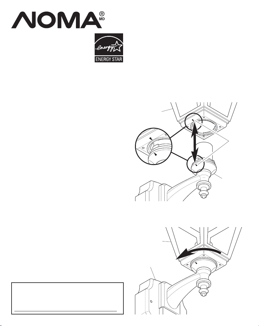
1. Place glass fixture onto base assembly.
LANTERN ASSEMBLY
2. Line up the arrow on the bottom of glass fixture
with the arrow on the fixture base (see illustration
below).
Glass Fixture
Arrows
Fixture Base
3. Gently push the two pieces together and rotate the
glass fixture 90° as shown below.
Glass Fixture
Before installation, record the model number listed
inside the xture. Attach receipt in case of possible
warranty issues.
Model Number:
Fixture Base
598-1286-01
Page 2
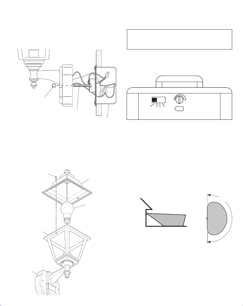
For best performance, mount the fixture about 6 feet (1.8
m) above the ground.
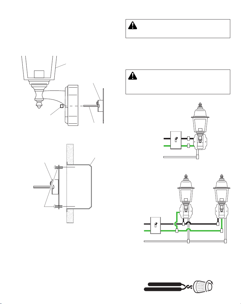
1. Remove two decorative nuts.
2. Remove X-Bar.
3. Tighten mounting screws on X-Bar finger tight.
4. Attach X-Bar to junction box.
Lantern
WIRINGINSTALLATION
WARNING: Turn power o at circuit breaker
or fuse.
Note: All wiring must be run in accordance with the
Canadian Electrical Code through conduit or another
acceptable means. Contact a qualified electrician if there
is any question as to the suitability of the system.
X-Bar
Decorative Nut
Lantern Mounting
Screw
Junction Box
X-Bar
Bracket Mounting
Screw
Note: We recommend having an assistant help hold the
lantern assembly during the wiring process.
CAUTION: DO NOT connect the RED wire unless
you want to control other lights from the motion
sensor (see Optional Wiring).
Black
Green or
Bare
White
One Motion Light
Black
Green or
Bare
White
Two Motion Lights
Connect the fixture wires to the wires in the junction
box. Twist the wires together and secure with wire connectors.
2
598-1286-01
Page 3
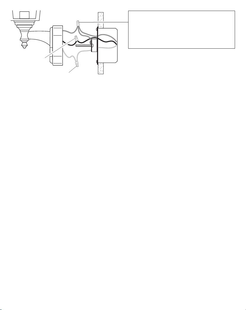
Recommended Grounding Method
Use a green ground “pigtail” (not provided) and twist
one end together with the bare fixture wire and the
box ground wire. Secure with a wire connector. Secure
the other end of the “pigtail” with the GND screw on
the X-bar.
Black to black
If you have metal junction box, you may not need the green
“pigtail”. If you are unsure about the grounding method,
consult your local building code.
White to white
598-1286-01
3
Page 4
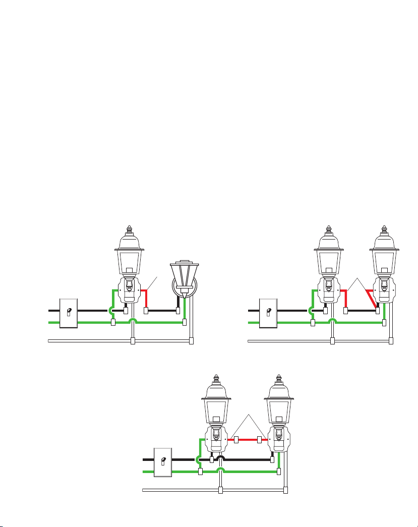
OPTIONAL WIRING
is fixture is provided with a sensor rated for 360 Watts. Since the fixture is only rated 100 Watts, 260 Watts of additional
lighting may be controlled by this sensor.
When determining what a fixture is rated for, do not simply look at the rating on the lamp in the fixture. Look at the
marking which specifies the maximum lamp wattage for which the fixture is suitable.
Once you have selected the fixtures to be connected and determined their maximum ratings, add these ratings up.
For instance, if you have 3 fixtures rated 100 Watts, 150 Watts, and 75 Watts respectively, you have a total load of 325
Watts.
Wiring Diagram 1 – When wiring to control a standard light xture: Strip the motion sensor’s red wire and con-
nect to the standard light’s black wire. Connect all white wires together. Total fixture ratings must not exceed 360 Watts
(3.0 A).
Wiring Diagram 2 – When wiring to control another motion sensing light xture (Master / Slave): Strip the
red wire in both light fixtures. Connect the red wire of the controlling (master) fixture to the red and black wires of the
controlled (slave) fixture. Connect all white wires together. Total fixture ratings must not exceed 360 Watts (3.0 A).
Wiring Diagram 3 – When wiring so either motion light turns on the both motion lights (Master / Master):
Strip the red wire in both light fixtures. Connect the red wire of one fixture to the red wire of the second fixture. Note:
In most installations, an additional wire (same gage as existing house wire) will have to be installed in the house to
connect the two fixtures as master / master. Connect all white wires together and all black wires together. Total fixture
ratings must not exceed 360 Watts (3.0 A).
Master
(Standard)
Slave
Black
Green or
Bare
White
Wiring Diagram 1
Black
Green or
Bare
White
Red
Green or
Master
Wiring Diagram 3
4
Red
Black
Bare
White
Wiring Diagram 2
Master
Red
598-1286-01
Page 5
1. Push the wires into the junction box. Make sure none
TEST 1 5 10
MINUTE
– +
SEN
FINAL ASSEMBLY
of the wires get pinched.
2.
Slide the fixture assembly onto the mounting screws.
Tighten decorative nuts removed in step 1 of Installation
section securely against fixture base.
Decorative Nut
Mounting Screw
Junction Box
3. Install one medium base light bulb (100 Watt maximum).
4. Place top cover onto fixture and attach using the two
decorative nuts (included). Hand tighten only.
5. After completing the tests on page 5, caulk around
fixture base with silicone weather sealant.
Decorative Nut
Top Cover
TESTING AND ADJUSTMENTS
1. Turn on the circuit breaker and light switch.
Note: Sensor has a 1 1/2 minute warm up period before
it will detect motion. When first turned on wait 1 1/2
minutes.
2. Set:
ON-TIME switch to TEST
SENSITIVITY dial to Midway
3.
Walk through the coverage area noting where you are
when the lights turn on. In TEST mode, light will stay
on for 5 seconds after sensing motion and then turn
off.
4. Adjust the SENSITIVITY to increase or decrease
the range as needed. Too much sensitivity may cause
false triggering due to heat sources in the coverage
area (see
Adjustment of Coverage Area or Troubleshooting
section).
5. Set the amount of ON-TIME you want the light to stay
on after motion is detected (1, 5, or 10 minutes).
Fixture Assembly
Caulk Around
Fixture Base
598-1286-01
Light Bulb (100
Watt Maximum)
180°
6 ft.
(1.8 m)
30 ft.
(9.1 m)
Maximum Range Maximum
Coverage Angle*
(Top View)
5
Page 6

e sensor is less sensitive to motion directly towards it
MANUAL MODE
AUTO
TEST
and more sensitive to motion across coverage area.
Motion Motion
MODE SWITCHING SUMMARY
ON-TIME Switch at 1, 5, or 10
minutes
Flip light switch o for one
second then back on*
Sensor
Least Sensitive Most Sensitive
OPERATION
Mode: On-Time Works: Day Night
Test
Auto
Manual
Note: When first turned on wait about 1 1/2 minutes for
5 Seconds
1, 5, or 10
Minutes
To Dawn*
* resets to Auto Mode at dawn.
the circuitry to calibrate.
x x
x
x
MANUAL MODE
Manual mode only works at night
because daylight returns the sensor
to AUTO.
Flip the light switch off for one second then back on to toggle between
AUTO and MANUAL MODE.
Manual mode works only with the
ON-TIME switch in the 1, 5, or
10 position.
1 Second OFF
then...
... back on.
* If you get confused while switching modes, turn the power
off for one minute, then back on. After the calibration time
the control will be in the AUTO mode.
ADJUSTMENT OF COVERAGE AREA
e sensor on this light fixture detects “motion” by the
movement of heat across the coverage area. However,
following are examples of objects that also produce heat
and can cause the sensor to trigger:
• Pools of Water • Air Conditioners
• Dryer Vents • Animals
• Heating Vents • Automobile Traffic
If you suspect that a heat source of this type is triggering
the sensor, reduce the sensitivity.
SPECIFICATIONS
Range ...............................Up to 30 ft. (9.1 m) [varies with
Sensing Angle
Electrical Load .................Up to 100 Watt Maximum
Bulb Type .........................Medium Base, Type “A”, 100
Sensor Capacity ................360 Watt (3.0 A) Maximum
Power Requirements .........120 VAC, 60 Hz
Operating Modes .............TEST, AUTO, and MANU
ON-Timer ........................1, 5, 10 minutes
Test Timer ........................5 Seconds
Manual Mode Timer ........
...................180°
surrounding temperature].
Tungsten Incandescent
Watt Maximum
Tungsten Incandescent
AL MODE
Dusk-to-Dawn
-
6
598-1286-01
Page 7

TROUBLESHOOTING
If you experience a problem, follow this guide.
SYMPTOM POSSIBLE CAUSE SOLUTION
Lights will not come
on.
Lights come on in day
light.
Lights come on for no
apparent reason.
Lights stay on continu
ously.
Lights flash on and off. 1. Light control is in the TEST mode and warm
1. Light switch is turned off.
2. Lamp is loose or burned out.
3. Fuse is blown or circuit breaker is turned off.
4. Daylight turn-off is in effect.
5. Incorrect circuit wiring, if this is a new installation.
-
1. Light control may be installed in a relatively
dark location.
2. Light control is in TEST.
1. Light control may be sensing small animals or
automobile traffic.
2. Sensitivity is set too high.
-
1. e sensor may be picking up a heat source
like an air vent, dryer vent, or brightly painted,
heat-reflective surface.
2. Light control is in Manual Mode.
3. Sensitivity is set too high.
ing up.
2. Heat being reflected from other objects may
be affecting the sensor.
No Service Parts Available for this Product
1. Turn light switch on.
2. Check lamp and replace if burned out.
3. Replace fuse or turn circuit breaker on.
4. Recheck after dark.
5. Verify wiring is correct.
1. e fixture is operating normally under these conditions.
2. Set control switch to 1, 5, or 10 minutes.
1. Reduce sensitivity.
2. Reduce sensitivity.
1. Reduce sensitivity.
2. Switch to Auto.
3. Reduce sensitivity.
-
1. Flashing is normal under these conditions.
2. Reduce sensitivity.
598-1286-01
7
Page 8

Modèles 52-4473-6
52-4474-4
Lanterne cochère
à détecteur de
mouvement
Instructions d'installation
et mode d'emploi
CARACTÉRISTIQUES
• S’allume automatiquement lors de la détection d’un
mouvement.
• S’éteint automatiquement.
• Cellule photo-électrique qui garde l’éclairage fermé
pendant la journée.
EXIGENCES
• La commande d’éclairage exige du courant 120 V c.a.
• Pour utiliser le mode de fonctionnement manuel, la commande d’éclairage doit être reliée à un interrupteur.
• Dans certaines localités, le code de l’électricité exige
que l’installation soit confiée à un électricien qualifié. Veuillez vérifier les codes en vigueur dans votre
région.
DÉBALLAGE
Retirez tout le contenu de l’emballage et assurez-vous
d’avoir en main tous les éléments avant de débuter l’assemblage. L’emballage contient les éléments suivants :
• Lanterne (comprend : couvercle supérieur, luminaire de
verre, socle du luminaire)
• Console de montage universelle (Barre-X)
• Ferrures de montage
• Serre-fils
• Guide du propriétaire
ASSEMBLAGE DE LA LANTERNE
1. Placez le luminaire de verre sur le socle.
2. Faites coïncider la flèche au bas du luminaire de verre
avec celle sur le socle (voir l’illustration ci-dessous).
Luminaire de
verre
Flèches
Socle du
luminaire
3. Insérez doucement les deux pièces l’une dans l’autre,
puis faites une rotation de 90 °, comme illustré cidessous.
Luminaire de
verre
Avant l’installation, inscrivez ici le numéro de
modèle qui se trouve à l’intérieur de l’appareil.
Joignez-y le reçu d’achat pour les réclamations
sous garantie.
Numéro de modèle :
Socle du luminaire
8
598-1286-01
598-1286-01 F
Page 9

Pour un rendement optimal, montez le luminaire à environ
1,8 m au-dessus du sol.
1. Retirez les deux écrous décoratifs.
2. Enlevez la barre-X.
3. Serrez à la main les vis de la croix en « X ».
4. Fixez la barre-X à la boîte de jonction.
Lanterne
CÂBLAGEINSTALLATION
MISE EN GARDE : Coupez l’alimentation au
disjoncteur ou au fusible.
Note : Le câblage doit être conforme aux exigences du
Code canadien de l’électricité et être installé dans des
canalisations ou autres dispositifs acceptables.
avez des doutes concernant la convenance du système,
consultez un électricien reconnu.
Si vous
Barre-X
Écrou décoratif
Vis de montage de
la lanterne
Boîte de jonction
Barre-X
Vis de montage du
support
Note : Il est recommandé de demander à une autre personne
de tenir la lanterne pendant le passage des fils.
AVERTISSEMENT: NE PAS raccorder le l ROUGE
à moins que vous ne vouliez commander d’autres
luminaires au moyen du détecteur de mouvement
(voir Câblage Facultatif).
Noir
Vert ou
dénudé
Blanc
Une lanterne à détecteur de mouvement
Noir
Vert ou
dénudé
Blanc
Deux lanternes à détecteur de mouvement
598-1286-01
Branchez les fils du luminaire aux fils dans la boîte de
raccordement. Torsadez ces fils ensemble, puis ajoutez-y
un connecteur de fils.
9
Page 10

Méthode de mise à la terre recommandée
Utilisez une «queue de cochon» verte (non fournie) et
torsadez-en une extrémité avec le fil nu du luminaire et
le fil de terre de la boîte de jonction. Utilisez un serre-fils.
Fixez l'autre extrémité de la «queue de cochon» avec la
vis de terre (GND) sur la plaque de montage.
noir/noir
blanc/blanc
Si la boîte de jonction est en métal, vous pourriez nécessiter une «queue de cochon» verte. Si vous avez des
doutes sur la méthode de mise à la terre, consultez votre
code du bâtiment.
10
598-1286-01
Page 11

CÂBLAGE FACULTATIF
Ce luminaire est pourvu d'un capteur de 360 W.
260 W d’éclairage supplémentaire.
Lorsque vous déterminez l'intensité que peut supporter un luminaire, ne vous contentez pas de simplement lire l'intensité
indiquée sur l'ampoule. Recherchez l'étiquette indiquant le wattage d'ampoule maximal de l'appareil.
Une fois que vous avez choisi les luminaires à raccorder et déterminé leur intensité maximale respective, additionnez les
intensités. Par exemple, si vous avex 3 appareils dont l'intensité est 100 Watts, 150 Watts et 75 Watts respectivement,
la charge totale est 325 Watts.
Diagramme de câblage 1 – Câblage d’un luminaire standard : dénudez le fil
et raccordez-le au fil noir du luminaire standard. Raccordez tous les fils blancs ensemble. L'intensité maximale ne noit
pas dépasser 360 Watts (3,0 A).
Diagramme de câblage 2 – Câblage d’un autre luminaire à détecteur de mouvement (Maître / Satellite) :
dénudez le fil rouge des deux luminaires. Branchez le fil rouge du luminaire de commande (maître) aux fils rouge et
noir du luminaire commandé (satellite). Branchez tous les fils blancs ensemble. La consommation totale des luminaires
ne doit pas être supérieure à 360 W (3,0 A).
Diagramme de câblage 3 – Câblage de sorte que l’une ou l’autre des commandes déclenche les deux lumi
naires (Maître / Maître) : dénudez le fil rouge des deux luminaires. Branchez le fil rouge d’un luminaire au fil rouge
du second luminaire. Note : Dans la plupart des cas, un fil supplémentaire (de même calibre que le fil de la résidence)
doit être installé pour raccorder les deux luminaires en configuration « principal / principal ». Raccordez tous les fils
blancs ensemble, puis faites de même avec tous les fils noirs. La consommation totale des luminaires ne doit pas être
supérieure à 360 W (3,0 A).
Comme ce luminaire ne consomme que 100 W, le capteur peut commander
rouge du détecteur de mouvement
Maître
(Standard)
Satellite
-
Noir
Vert ou
dénudé
Blanc
598-1286-01
Diagramme de câblage 1
Noir
Vert ou
dénudé
Blanc
Rouge
Diagramme de câblage 3
Maître
11
Noir
Vert ou
dénudé
Blanc
Rouge
Diagramme de câblage 2
Maître
Rouge
Page 12

1. Repoussez les fils dans la boîte de raccordement.
TEST 1 5 10
MINUTE
– +
SEN
ASSEMBLAGE FINAL
Assurez-vous qu’aucun des fils n’est pincé.
2. Faites glisser le socle du luminaire sur les vis de
montage. Serrez solidement sur le socle les écrous
décoratifs retirés à l’étape 1, à la section
Écrou décoratif
Vis de montage
3. Installez une ampoule à culot moyen (maximum de
100 W).
4. Placez le couvercle supérieur sur le luminaire et fixez-le
au moyen des deux écrous décoratifs fournis. Serrez à
la main seulement.
5. Après avoir effectué les essais de la page 12, appliquez
un agent d’étanchéité à base de silicone autour du socle
mural.
Écrou décoratif
Installation
Boîte de jonction
Couvercle supérieur
Ampoule (100 W
maximum)
ESSAIS ET RÉGLAGES
1. Ré-enclenchez le disjoncteur puis ouvrez l’inter-
rupteur.
Note : Le capteur exige 1 1/2 minute avant de détecter
.
les mouvements. Lors de la première mise sous tension,
attendez 1 1/2 minute.
2. Réglages :
Commutateur ON TIME à TEST
Cadran SENSITIVITY au milieu
3. Déplacez-vous dans la zone de couverture en notant
l’endroit où vous vous trouvez lorsque l’éclairage
s’allume. En mode TEST, l’éclairage demeure allumé
pendant 5 secondes après qu’un mouvement est dé
tecté.
4. Réglez la SENSIBILITÉ (SENSITIVITY) afin d’augmenter ou de réduire la couverture, au besoin. Une trop
grande sensibilité pourrait entraîner des déclenchements
intempestifs attribuables à des sources de chaleur dans
la zone de couverture (consultez les sections
la zone de couverture ou Dépannage
5.
Réglez la période (ON TIME) pendant laquelle vous
souhaitez que l’éclairage fonctionne après détection d’un
mouvement (1, 5 ou 10 minutes).
).
-
Réglage de
180°
Luminaire
Agent d’étanchéité
autour du socle
1,8 m
9,1 m
Portée maximale Angle de
couverture maximale
(Vue en plongée)
12
598-1286-01
Page 13

Le capteur est moins sensible aux déplacements directement
PRIORITÉ MANUELLE
AUTO
TEST
vers lui; il est plus sensible aux mouvements traversant la
zone de couverture.
MouvementMouvement
RÉSUMÉ DU MODE DE COMMUTATION
Placer l’interrupteur ON-TIME à
1, 5 ou 10 minutes
Mettre l’interrupteur hors
circuit pendant une seconde, puis le remettre
en circuit
Capteur
Le moins sensible Le plus sensible
FONCTIONNEMENT
Mode: Temps en circuit:
Essai
Auto
Manuel
* Revient au mode automatique au lever du soleil.
Note: Ap rès mise en circuit, attendre enfiron
1 1/2 minute pour que l’étalonnage du circuit soit
complété.
5 secondes
1, 5 ou 10 min. x
au choix, amanecer*
En fonction:
jour nuit
x x
x
PRIORITÉ MANUELLE
Le mode manuel ne fonctionne
que la nuit parce que la lumière
du jour remet le capteur en
mode AUTO.
Mettre l’interrupteur hors
circuit pendant une seconde,
plus en circuit pour alterner
entre les modes AUTO et
MANUEL.
Le mode manuel ne fonctionne
que lorsque l’interrupteur
ON-TIME est aux positions
1, 5 ou 10.
hors circuit pendant
1 seconde, puis ...
... à nouveau en circuit
* Si vous ne savez plus dans quel mode se trouve l’appareil,
couper l’alimentation pendant une minute puis la rétablir.
Après le temps d’étalonnage, la commande reviendra au
mode AUTO.
RÉGLAGE DE LA ZONE DE COUVERTURE
Le capteur de ce luminaire détecte les mouvements lors
des « déplacements de chaleur » dans la zone de couverture. Quoi qu’il en soit, les objets suivants produisent
aussi de la chaleur et peuvent entraîner le déclenchement
du capteur :
• Piscine • Appareil de climatisation
• Évent de sécheuse • Animaux
• Évent de ventilation • Circulation automobile
Si vous croyez qu’une source de chaleur de ce type déclenche
le capteur, réduisez sa sensibilité.
598-1286-01
13
Page 14

FICHE TECHNIQUE
Portée ........................Jusqu’à 9,1 m [varie selon la tem-
Angle de détection .....
Charge électrique ....... Jusqu’à 100 W maximum Tungstène
Type d’ampoule ......... Culot moyen, type A, 100 W
Capacité du
détecteur .................... Jusqu’à 360 W (3,0 A) maximum
pérature environnante].
180°
à incandescence.
maximum
Tungstène à incandescence
Courant requis ...........120 V c.a., 60 Hz
Modes de
fonctionnement .........ESSAI, AUTO et MANUEL
Minuterie de
fonctionnement .........1, 5 ou 10 minutes
Minuterie d’essai ........5 secondes
Minuterie du mode
MANUEL ................
Du coucher au lever du soleil
Si vous éprouvez des difficultés, suivez ce guide.
DÉPANNAGE
SYMPTOM POSSIBLE CAUSE SOLUTION
L’éclairage ne s’allume
pas.
L’éclairage s’allume en
plein jour.
L’éclairage s’allume sans
raison apparente.
L’éclairage demeure al
lumé continuellement.
L’éclairage clignote. 1. La commande d’éclairage est en mode essai et
1. L’interrupteur d’éclairage est hors tension.
2. L’ampoule est lâche ou grillée.
3. Le fusible a sauté ou le disjoncteur a été déclenché.
4. La fonction de fermeture pendant le jour est
activée.
5. Mauvais câblage du circuit, dans le cas d’une
nouvelle installation.
1. La commande peut être installée dans un
endroit relativement sombre.
2. La commande d’éclairage est en mode essai.
1. Le capteur détecte peut-être de petits animaux ou
la circulation automobile.
2. Le réglage de portée est trop élevé.
-
1. Le capteur peut percevoir une source de chaleur
comme une sortie d’air, un évent de sécheuse
ou une surface de couleur claire réfléchissant
la chaleur.
2. La commande d’éclairage est en mode Manuel.
3. Le réglage de portée est trop élevé.
se réchauffe.
2.
La chaleur qui est réfléchie par d’autres objets peut
affecter la commande d’éclairage.
1. Mettre l’interrupteur sous tension.
2. Vérifier l’ampoule et la remplacer si elle est grillée.
3. Remplacer le fusible ou réenclencher le disjoncteur.
4. Essayer de nouveau après la tombée de la nuit.
5. S’assurer que le câblage est approprié.
1. Le luminaire fonctionne normalement dans de telles
conditions.
2. Réglez le commutateur de commande à 1, 5 ou 10
minutes.
1. Réduisez la portée.
2. Réduisez la portée.
1. Réduisez la portée.
2. Faites-la passer au mode Auto.
3. Réduisez la portée.
1. Le clignotement est normal dans ces deux cas.
2. Réduisez la portée.
Aucune pièce de rechange n’est disponible pour ce produit.
14
598-1286-01
Page 15

NOTES____________________________
__________________________________
__________________________________
__________________________________
__________________________________
__________________________________
__________________________________
__________________________________
__________________________________
__________________________________
__________________________________
__________________________________
__________________________________
__________________________________
__________________________________
__________________________________
__________________________________
__________________________________
598-1286-01
15
Page 16

NOTES____________________________
__________________________________
__________________________________
__________________________________
__________________________________
__________________________________
__________________________________
__________________________________
__________________________________
__________________________________
__________________________________
__________________________________
__________________________________
__________________________________
__________________________________
__________________________________
__________________________________
__________________________________
16
598-1286-01
 Loading...