

Page 1
DU
AL
B
RITE
®
O
N-
TI
ME
TE
S
T 1
5
10
M
I
N
O
FF
3
6
DU
S
K
TO
DA
W
N
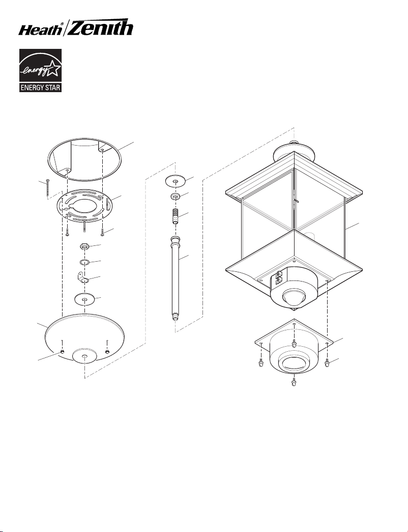
Motion Sensing Pendant Light
Meets the ENERGY STAR
lines when DualBrite® function
is off.
Model 4350
1
8
®
guide-
FEATURES
• Light comes on when motion is detected.
• Automatically turns light off.
• Optional half power accent lighting.
• Photocell keeps the light off during daylight
hours.
• Hinged door for easy bulb access.
Junction Box
(Not Included)
10
2
3
4
5
6
7
11
12
14
13
15
9
16
Be sure to remove all contents from packaging and verify all items are present before assembling this
light xture. This package includes the following items:
1 - Canopy Screws (x3)
2 - Universal Mounting Bracket
3 - Mounting Bracket Screws
(x2)
4 - Nut
5 - Star Washer
6 - S-Hanger Terminal
7 - Flat Washer
8 - Canopy
© 2007 HeathCo LLC 598-1219-05
9 - Knurled Canopy Nuts (x3)
10 - Decorative Flat Washer
11 - Small, Thick, Decorative
Washer
12 - 1" (25.4 mm) Threaded
Rod
13 - Mounting Rods (x3)
- 6" (15.2 cm) Rod
- 12" (30.5 cm) Rod (x2)
14 - Pendant Light Fixture
15 - Sensor Cover
16 - Sm o o t h Sensor C o v e r
Screws (x4)
Other Items Not Shown:
- Wire Nuts (x3)
- Lens Shield (x2)
- S-Hanger
- Foam Tape
Page 2
MANUAL MODE
AUTO
TEST
Before installation, record the model number
listed inside the xture. Attach receipt in case
of possible warranty issues.
Model Number:
REQUIREMENTS
• The light control requires 120 volts AC.
• If you want to use Manual Mode, the control must
be wired through a switch.
• Some electrical codes require installation by
a qualied electrician.
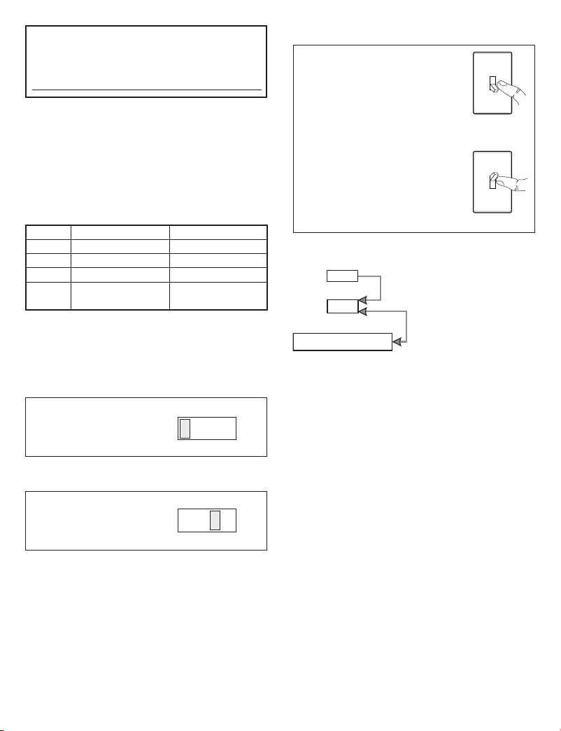
OPERATION
Mode: On-Time Works: Day Night
Test 5 Seconds
Auto 1, 5, or 10 Min
Manual To Dawn* x
Accent Off, 3, 6 Hr,
to Dawn
* resets to Auto Mode at dawn.
Note: When rst turned on wait about 1 1/2 minutes
for the circuitry to calibrate.
x x
x
x
TEST
Set the ON-TIME switch
on the sensor to TEST.
ON-TIME
TEST 1 5 10 MIN
AUTO
Set ON-TIME switch to
1, 5, or 10 minutes.
ON-TIME
TEST 1 5 10 MIN
MANUAL MODE
Manual mode only works at
night because daylight returns
the sensor to AUTO.
Flip the light switch off for
one second then back on to
toggle between AUTO and
MANUAL MODE.
Manual mode works only with
the ON-TIME switch in the 1,
5, or 10 position.
1 Second OFF
then...
... back on.
MODE SWITCHING SUMMARY
ON-TIME Switch at 1, 5, or
10 minutes
Flip light switch off
for one second then
back on*
* If you get confused while switching modes, turn the
power off for one minute, then back on. After the calibration time the control will be in the AUTO mode.
DualBrite® DIMMER CONTROL
Light comes on half bright for selected time after
dusk (Off, 3 hr., 6 hr., until dawn). Selecting OFF
disables this feature. The motion sensing features
will continue to work as described in this manual.
If motion is sensed, the light turns on full bright for
the ON-TIME (1, 5, or 10 minutes) then returns
to dim mode.
2
598-1219-05
Page 3
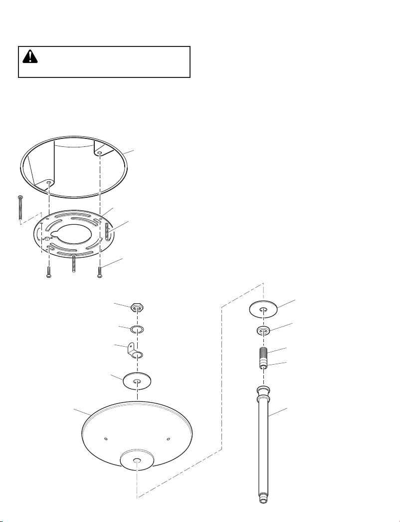
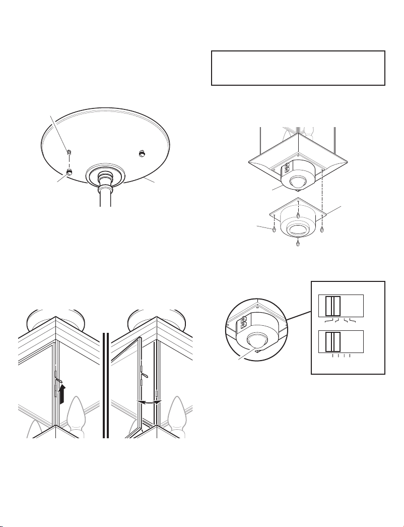
INSTALL UNIVERSAL MOUNTING
BRACKET
WARNING: Turn power off at circuit
breaker or fuse.
1. Remove universal mounting bracket from canopy
by removing the 3 knurled canopy nuts.
2. Tighten the three canopy screws nger tight.
3. Attach universal mounting bracket to junction
box securely with the two screws provided.
Junction Box
Universal Mounting
Bracket
Canopy Screw (x3)
(Tightened Finger
Tight)
Mounting Bracket
Screw (x2)
1. Determine the number of mounting rods needed
ASSEMBLE CANOPY
to mount the pendant light. Any combination of
the 3 mounting rods may be used. Note: For
best performance, mount the xture so that the
sensor is between 8 and 10 feet (2.4 m) above
the ground.
2. Determine which mounting rod will connect to
canopy.
3. Locate the 1" (25.4 mm) threaded rod.
4. Connect the end of the threaded rod with the
thread sealant to the mounting rod that will
connect to the canopy. Hand tighten securely.
Note: Excess sealant may have to be trimmed
away for best appearance.
5. Place the small, thick, decorative washer onto
the threaded rod.
6. Place the decorative at washer onto the
threaded rod.
7. Place canopy onto threaded rod.
8. Place the other large washer onto the threaded
rod.
9. Place the S-Hanger Terminal onto the threaded
rod with tab facing away from canopy.
10. Place star washer onto threaded rod.
11. Screw nut onto threaded rod and tighten securely with wrench.
598-1219-05
Star Washer
S-Hanger Terminal
Flat Washer
Canopy
Nut
Decorative Flat Washer
Small, Thick,
Decorative Washer
1" (25.4 mm) Threaded Rod
End with Thread
Sealant
Mounting Rod
3
Page 4
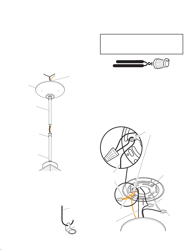
ASSEMBLE PENDANT LIGHT
1. Route light xture wires through mounting rod
(threaded end rst) that will connect to the
xture.
2. Screw rod into light xture. Tighten mounting
rod securely.
3. Continue this process until desired number of
mounting rods are connected to light xture
(including the rod connected to the canopy).
IMPORTANT: TIGHTEN all connections
securely.
Note: If necessary, trim away any excess thread
sealant for best appearance.
2. Trim light xture wire length if needed.
3. Connect the junction box wires and the xture
wires together as shown in the following diagram.
4. Twist and secure wires with wire nuts.
IMPORTANT: This light xture is polarized.
Connect the ribbed wire to the house white
wire. Connect the wire with writing on it to the
house black wire.
Fixture Bare
Canopy
Mounting Rod
(Attached to
Canopy)
Light Fixture Wiring
First Mounting Rod
Ground Wire
WIRING LIGHT FIXTURE
Note: All wiring should be run in accordance with
the National Electrical Code through conduit or
another acceptable means. Contact a qualied
electrician if there is any question as to the
suitability of the system.
1. To simplify installation, attach one end of S-hanger
to S-hanger terminal (located inside canopy) and
the other end to mounting
bracket.
S-Hanger
S-Hanger
Terminal
Recommended Grounding Method
1. Loop the xture ground wire around the xture
ground screw (located on mounting bracket)
once.
2. Tighten ground screw.
3. Attach end of xture ground wire to the bare
ground wire inside the junction box using supplied wire nut.
If you are uncertain about the grounding method,
consult your local building code.
Fixture Ground Screw
Fixture Bare
Ground Wire
Bare Ground
Wire
S-Hanger
Junction Box
Black to Wire
with Text
Printed On It
White to
Ribbed Wire
4
598-1219-05
Page 5
INSTALL PENDANT LIGHT TO
DU
AL
BRIT
E
®
O
N-
T
I
ME
TE
ST
1
5
10
M
I
N
O
FF
3
6
DU
S
K
TO
DA
W
N
DUAL
B
R
IT
E
®
O
N-
T
IME
T
E
ST
1
5
10 MI
N
O
FF
3
6
DU
S
K
T
O
DA
WN
DualBrite
®
ON-TIME
DUSK
OFF
3HR 6HR TO DAWN
TEST 1 5 10 MIN
JUNCTION BOX
1. Push wires into the junction box.
2. Remove S-Hanger.
3. Slide canopy onto canopy screws and tighten
knurled canopy nuts securely against the
canopy. Note: Canopy should t tight against
mounting surface.
Canopy Screw
Knurled
Canopy Nut
Canopy
BULB INSTALLATION AND
REPLACEMENT
1. Slide door latch up to unlock door. Pull latch to
open door.
2. Install two candelabra base light bulbs (60
Watts maximum each).
3. After installing bulbs, close door and slide latch
down to securely lock door.
1. Turn on the circuit breaker and light
TESTING
switch.
Note: Sensor has a 1 1/2 minute warm up period
before it will detect motion. When rst turned on
wait 1 1/2 minutes.
2. To remove sensor cover, unscrew the 4 sensor cover screws holding the sensor cover on
bottom of light xture.
Sensor
Sensor Cover
Sensor Cover
Nut
3. Set the ON-TIME switch to the TEST position and
the DualBrite® switch to the OFF position.
Lift Latch Up Open Door
598-1219-05
Sensor
Lens
4. Walk through the coverage area noting where
you are when the lights turn on. In TEST mode,
light will stay on for only 5 seconds then turn
off.
5
Page 6
5. Adjust the SENSITIVITY to increase or de-
SE
N
SITIV
IT
Y
+
–
+
–
SENSITIVITY
crease the range as needed. Too much sensitivity may cause false triggering due to heat
sources in the coverage area (see Adjustment of
Coverage Area or Troubleshooting section).
6. Set the amount of ON-TIME you want the light
to stay on after motion is detected (1, 5, or 10
minutes).
7. Set the amount of time you want the light to
stay on in the Accent mode (Off, 3 hours, 6
hours, or dusk-to-dawn).
Note: Meets the ENERGY STAR® guidelines when
DualBrite® function is off.
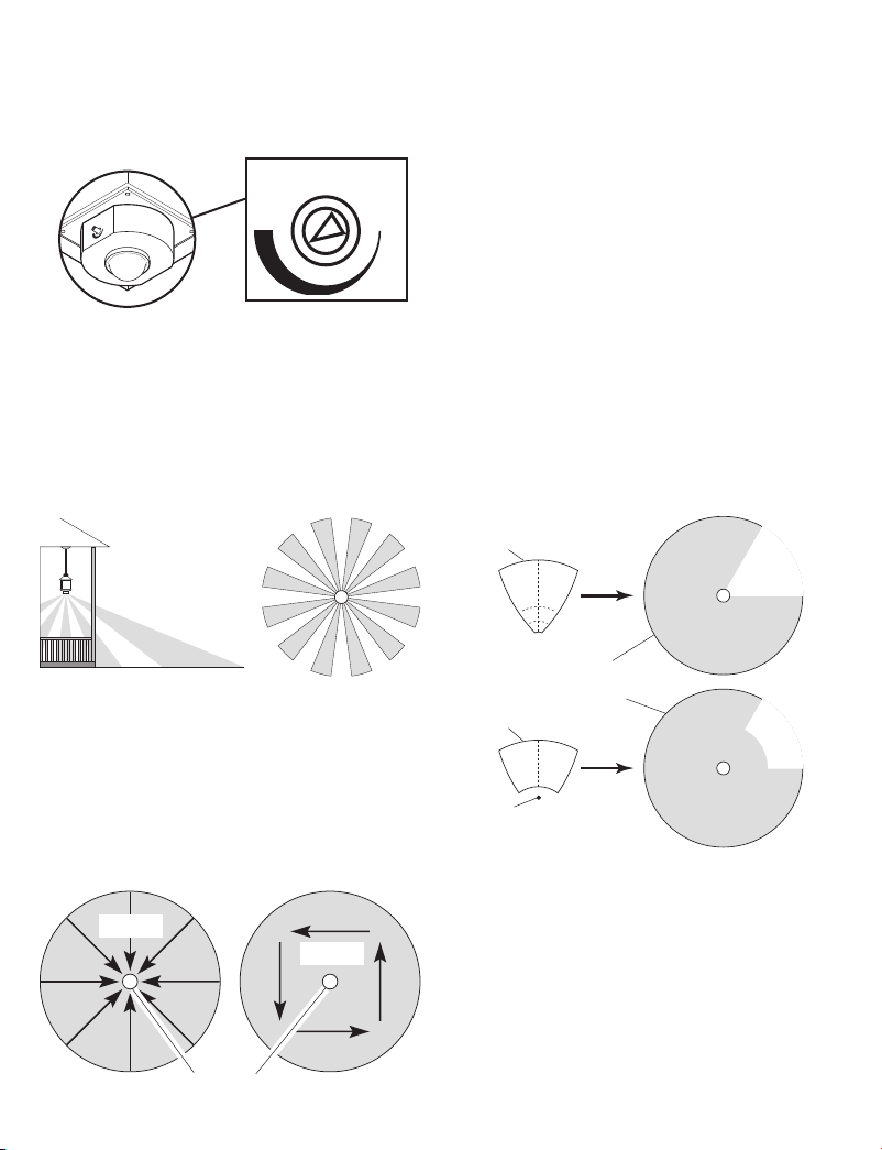
360°
8 ft. (2.4 m)
ADJUSTMENT OF COVERAGE
AREA
The sensor on this light xture detects “motion”
by the movement of heat (body heat) across the
coverage area. However, following are examples
of objects that also produce heat and can cause
the sensor to false trigger:
• Pools of Water • Air Conditioners
• Dryer Vents • Fenced-In Animals
• Heating Vents • Automobile Trafc
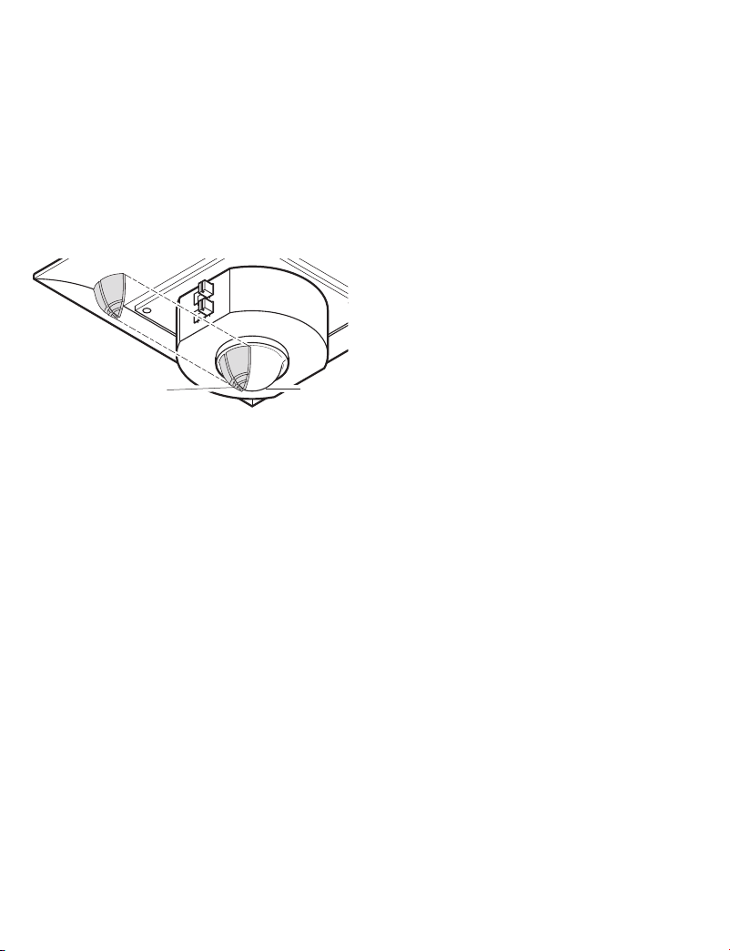
If you suspect that a heat source of this type is falsely
triggering the sensor and reducing the sensitivity
does not solve the problem, then a lens shield
(included) can be installed. The plastic lens shield
is divided into 6 sections. Each section will reduce the
coverage angle by 30 degrees. Also, the tip of each
section may be removed to change the effective
range of the sensor.
1. Break off the amount of lens shield needed to
block the desired area of coverage.
Lens
Shield
Area
Blocked
30 Feet (9.1 m)
in all Directions
Maximum Range Coverage Angle*
(Top View)
* Without lens shield installed.
The sensor is less sensitive to motion directly
towards it and more sensitive to motion across
coverage area.
Motion
Motion
Least Sensitive Most Sensitive
Sensor
6
Effective Coverage
Area (Top View)
Lens
Shield
Portion
Removed
Area
Blocked
598-1219-05
Page 7
DUAL
B
R
IT
E
®
O
N-
T
IME
T
E
ST
1
5
10 MI
N
O
FF
3
6
DU
S
K
T
O
DA
WN
2. Cut desired amount of foam tape needed to
adhere the lens shield to the sensor lens.
3. Remove paper backing from one side of cut
foam tape and adhere foam tape to inside of
lens shield.
4. Remove paper backing from other side of cut foam
tape and adhere lens shield to sensor lens.
5. Retest to conrm that the sensor is no longer
false triggering.
6. After switches are set and testing is complete,
use the 4 sensor cover screws to install the
sensor cover.
Lens Shield
Sensor
Lens
Note: To help determine amount of lens shield
required, apply small sections one at a time. Additional sections can be applied if necessary.
SPECIFICATIONS
Range ........................... Up to 30 ft. (9.1 m)
Sensing Angle
...............360°
Electrical Load .............. Up to 120 Watt
Bulb Type ......................Candelabra Base, Type
Power Requirements ....
Operating Modes .......... TEST, AUTO/ACCENT,
ON-Timer ......................1, 5, 10 minutes
ualBrite
®
Timer ..........Off, 3, 6 Hrs, Dusk-to-
D
HeathCo LLC reserves the right to discontinue
products and to change specications at any time
without incurring any obligation to incorporate new
features in products previously sold.
[varies with surrounding
temperature].
Maximum Tungsten
Incandescent (Up to 60
Watt Maximum each
lampholder).
“B”, 60 Watt Maximum
120 VAC, 60 Hz
and MANUAL MODE
Dawn
598-1219-05
7
Page 8

TROUBLESHOOTING GUIDE
SYMPTOM
Li g h t wi l l no t
come on.
Light comes on
in daylight.
Light comes on
for no apparent
reason.
POSSIBLE CAUSE
1. Light switch is turned off.
2. Bulbs are loose or burned out.
3. Fuse is blown or circuit breaker
is turned off.
4. Daylight turn-off is in effect
check after dark).
5. Incorrect circuit wiring, if this is
a new installation.
1. Sensor may be installed in a
relatively dark location.
2. Sensor is in Test. (Set control
switch to an ON-TIME position.)
1. Sensor may be sensing small
animals or automobile traffic.
(Reduce sensitivity.)
(re-
SYMPTOM
Light stays on
continuously.
Light ashes on
and off.
Light does not
stay on in Man-
ual mode.
POSSIBLE CAUSE
1. There is a heat source like an
air vent, dryer vent, or brightly-
painted, heat-reective surface in
the coverage area. (Install shield
on sensor in the direction of heat
source.)
2. Sensor is in Manual Mode. (Switch
to Auto.)
3. Sensor is in DualBrite® mode.
4. Sensitivity is set too high. (Reduce
sensitivity.)
1. Sensor is in the Test mode. (While
in TEST mode, light only stays on
for 5 seconds.)
1. Nearby large, light-colored objects
reecting light may trigger the
shut-off feature. Do not point other
lights at the sensor.
TECHNICAL SERVICE
Please call 1-800-858-8501 (English speaking only) for assistance before returning
product to store.
If you experience a problem, follow this guide. You may also want to visit our Web site at: www.hzsupport.com. If the problem persists, call* for assistance at 1-800-858-8501 (English speaking only), 7:30
AM to 4:30 PM CST (M-F). You may also write* to:
HeathCo LLC
P.O. Box 90004, Bowling Green, KY 42102-9004
ATTN: Technical Service
* If contacting Technical Service, please have the following information available: Model Number, Date
of Purchase, and Place of Purchase.
No Service Parts Available for this Product
This is a “Limited Warranty” which gives you specic legal rights. You may also have other rights which vary from state to state or
province to province.
For a period of ve years from the date of purchase, any malfunction caused by factory defective parts or workmanship will be corrected at no charge to you.
Not Covered - Repair service, adjustment and calibration due to misuse, abuse or negligence, light bulbs, batteries, and other ex-
pendable items are not covered by this warranty. Unauthorized service or modication of the product or of any furnished component
will void this warranty in its entirety. This warranty does not include reimbursement for inconvenience, installation, setup time, loss
of use, unauthorized service, or return shipping charges.
This warranty covers only HeathCo LLC assembled products and is not extended to other equipment and components that a customer
uses in conjunction with our products.
THIS WARRANTY IS EXPRESSLY IN LIEU OF ALL OTHER WARRANTIES, EXPRESS OR IMPLIED, INCLUDING ANY WARRANTY,
REPRESENTATION OR CONDITION OF MERCHANT ABILITY OR THAT THE PRODUCTS ARE FIT FOR ANY PARTICULAR PURPOSE OR USE, AND SPECIFICALLY IN LIEU OF ALL SPECIAL, INDIRECT, INCIDENTAL, OR CONSEQUENTIAL DAMAGES.
REPAIR OR REPLACEMENT SHALL BE THE SOLE REMEDY OF THE CUSTOMER AND THERE SHALL BE NO LIABILITY ON
THE PART OF HEATHCO LLC FOR ANY SPECIAL, INDIRECT, INCIDENTAL, OR CONSEQUENTIAL DAMAGES, INCLUDING
BUT NOT LIMITED TO ANY LOSS OF BUSINESS OR PROFITS, WHETHER OR NOT FORESEEABLE. Some states or provinces
do not allow the exclusion or limitation of incidental or consequential damages, so the above limitation or exclusion may not apply to
you. Please keep your dated sales receipt, it is required for all warranty requests.
FIVE YEAR LIMITED WARRANTY
8
598-1219-05
Page 9

DU
AL
B
RI
TE
®
O
N-
TI
ME
TE
S
T 1
5
10
M
I
N
O
FF
3
6
DU
S
K
TO
DA
W
N
Modelo 4350
Cumple con las normas ENERGY
STAR® cuando la función DualBrite®
está apagada.
Lámpara colgante con detector
de movimiento
CARACTERÍSTICAS
Caja de empalmes
(no incluida)
• La luz se prende cuando se detecta movimiento.
• Apaga la luz automáticamente.
•
Alumbrado decorativo opcional a media potencia.
• La fotocélula mantiene la luz apagada durante
las horas del día.
• Puerta abisagrada para tener fácil acceso a la
bombilla.
1
2
10
11
12
3
14
4
5
13
6
7
8
15
9
16
Asegúrese de retirar todo el contenido del paquete y vericar que todas las partes estén incluidas antes
de ensamblar este artefacto de luz. Este paquete incluye las siguientes partes:
1 - Tornillos del escudete (x3)
2 -
Consola universal de montaje
3 - Tornillos de la consola de
montaje (x2)
4 - Tuerca
5 - Arandela estrellada
6 - Terminal de la percha-S
7 - Arandela plana
8 - Escudete
9 - Tuercas estriadas del
10 - Arandela decorativa plana
11 - Arandela decorativa
pequeña, gruesa
12 - Varilla roscada de 25,4 mm
(1 pulg.)
13 - Varillas de montaje (x3)
- Varilla de 15,2 cm
(6 pulg.)
- Varilla de 30,5 cm
(12 pulg.) (x2)
14 - Artefacto colgante de luz
15 - Tapa del detector
16 - Tornillos de la tapa del
detector liso
Otros elementos no mostrados:
- Conectores de alambre (x3)
- Cubierta de la placa
traslúcida (x2)
- Percha-S
- Cinta espumosa
escudete (x3)
598-1219-05
© 2007 HeathCo LLC 598-1219-05 S
9
Page 10

PRUEBA
AUTOM.
MODO
MANUAL
Antes de instalar, registre el número del modelo
mostrado dentro del aparato. Fije el recibo en
caso posibles reclamos por la garantía.
Número del modelo:
REQUISITOS
• El control de luz requiere 120 VCA.
• Para usar el Sobrecontrol Manual, conecte el
control con un interruptor.
• Algunos códigos requieren instalación por
un electricista calicado.
MODO MANUAL
El modo manual funciona sólo
por la noche porque la luz del
día pone al detector en modo
AUTOMATICO.
Apague el interruptor por un se
gundo y vuélvalo a prender.
El modo manual funciona sólo
cuando el interruptor de tiempo
(ON-TIME) está en la posición
de 1, 5 ó 10 minutos.
-
1 segundo
APAGADO
luego...
FUNCIONAMIENTO
Modalidad: A tiempo: Trabaja: Día Noche
Prueba 5 seg. x x
Autom. 1, 5, ó 10 min. x
Manual Hasta el
amanecer*
Adorno Apagado, 3,6
hrs, hasta el
amanecer
*Se pone en Automático al amanecer.
Nota: Cuando lo prenda por primera vez espere
1 1/2 minutos para que el circuito se claibre.
x
x
PRUEBA
Ponga el interruptor de
ON-TIME (DURACIÓN)
del detector en TEST
(PRUEBA).
ON-TIME
TEST 1 5 10 MIN
AUTOMATICO
Ponga el interruptor de
tiempo (ON-TIME) en
la posición de 1, 5 ó 10
minutos.
ON-TIME
TEST 1 5 10 MIN
...préndalo.
RESUMEN DE LAS MODALIDADES
DEL INTERRUPTOR
Mueva el interruptor de tiempo
(ON-TIME) a 1, 5 ó 10 minutos
Apague el interruptor por
un segundo y préndalo de
nuevo*
* Si se confunde mientras cambia de fases, apa-
gue la electricidad por un minuto y préndala de
nuevo. Después del tiempo de calibración el
control estará en fase AUTO(MATICA).
LUZ DE ADORNO (DualBrite®)
La luz se prende con media brillantez por el tiempo
escogido después del atardecer (apagado, 3 hr.,
6 hrs., hasta el amanecer). Si escoge OFF (APAGADO) deshabilita esta función. Las funciones
que detectan movimiento continuarán funcionando
como se describen en este manual. Si detecta mo-
vimiento, la luz se prende con todo su resplandor
por el tiempo de duración o de ON-TIME (1, 5 ó
10 minutos) y luego regresa a media luz.
10
598-1219-05
Page 11

INSTALE LA CONSOLA UNIVERSAL
DE MONTAJE
ADVERTENCIA: Desconecte la
energía en el disyuntor.
1.
Retire del escudete la consola universal de montaje
retirando las 3 tuercas estriadas del escudete.
2. Apriete a mano las tres tuercas del escudete.
3. Sujete bien la consola universal de montaje
a la caja de empalmes con los dos tornillos
provistos.
Caja de empalme
Soporte universal
de montaje
Tornillo del escudete (x3) (apretado a
mano)
Tornillo de la consola
de montaje (x2)
ENSAMBLE EL ESCUDETE
1. Determine el número de varillas de montaje que
necesita para montar la lámpara colgante. Se
puede usar cualquier combinación de las 3 varillas
de montaje. Nota: Para un mejor desempeño
monte el artefacto de modo que el detector esté
entre 2,4m (8 y 10 pies) por encima del suelo.
2. Determine la varilla de montaje que va a conectar al escudete.
3. Localice la varilla roscada de 25,4 mm (1 pulg.).
4. Conecte el extremo de la varilla roscada que tiene
sellador de roscas a la varilla de montaje que va
a conectar al escudete. Apriete bien a mano.
Nota: Para dar una mejor apariencia puede
que tenga que recortarse y retirarse el exceso
de sellante.
5. Coloque la arandela decorativa pequeña y
gruesa en la varilla roscada.
6. Coloque la arandela decorativa plana en la
varilla roscada.
7. Coloque el escudete en la varilla roscada.
8. Coloque la arandela grande en la varilla
roscada.
9. Coloque el terminal de la percha-S en la varilla
roscada con la aleta hacia fuera del escudete.
10. Coloque la arandela estrellada en la varilla
roscada.
11. Enrosque la tuerca en la varilla roscada y
apriete bien con una llave.
598-1219-05
Tuerca
Arandela estrellada
Terminal percha en S
Arandela plana
Escudete
Arandela decorativa plana
Arandela decorativa
pequeña, gruesa
Varilla roscada de 25,5 mm (1 pulg.)
Extremo con sellador
de roscas
Varilla de montaje
11
Page 12

ENSAMBLE LA LÁMPARA
COLGANTE
1. Pase los conductores del artefacto de luz a través de la varilla de montaje (primero el extremo
roscado) que va a conectar al artefacto.
2. Enrosque la varilla en el artefacto de luz. Apriete
bien la varilla de montaje.
3. Siga este proceso hasta que al artefacto de
luz estén conectadas el número deseado
de varillas de montaje (incluyendo la varilla
conectada al escudete).
IMPORTANTE: APRIETE bien todas las
conexiones.
Nota: Si es necesario, recorte y retire cualquier
exceso del sellador de roscas para dar una mejor
apariencia.
Conductor
desnudo de
Escudete
Varilla de montaje
(Sujeto al escudete)
Cableado del
artefacto de luz
puesta a tierra
del artefacto
2. Si es necesario recorte el conductor del arte-
facto de luz.
3. Conecte entre sí los conductores de la caja de
empalmes con los del artefacto de luz como
se muestra en la siguiente ilustración.
4. Enrosque y asegure los conductores con
conectores de alambre.
IMPORTANTE: Este artefacto de luz está polarizado. Conecte el conductor rayado al conductor
blanco de la casa. Conecte el conductor con
escritura al conductor negro de la casa.
MÉTODO RECOMENDADO DE
PUESTA A TIERRA
1. Dé una vuelta el conductor de tierra del artefacto
alrededor del tornillo de tierra del artefacto (que
está en la consola de montaje).
2. Apriete el tornillo de puesta a tierra.
3. Conecte el extremo del conductor de puesta
a tierra del artefacto al conductor desnudo de
puesta tierra, que viene de la caja de empalmes,
usando el conector de alambres provisto.
Si tiene dudas en cuanto al método de puesta a tierra,
consulte el código de la construcción de su localidad.
Tornillo de puesta a
tierra del artefacto
Primera varilla
de montaje
CABLEADO DEL APARATO DE LUZ
Nota: Todo el cableado debe ser hecho de acuerdo
al Código Eléctrico Nacional por medio de conductos para cables u otras formas aceptables. Póngase
en contacto con un electricista calicado si
existe duda sobre la aptitud del sistema.
1. Para simplicar la instalación, sujete un extremo
de la percha-S al terminal
de la percha-S (que está
dentro del escudete) y el
otro extremo a la consola
de montaje.
Percha-S
Terminal
de la
percha-S
Conductor
desnudo de
puesta a tierra
del artefacto
Conductor desnudo
de conexión a tierra
Percha-S
12
Caja de empalme
El negro con
el conductor
con escritura
impresa
El blanco con
conductor rayado
598-1219-05
Page 13

INSTALACIÓN DE LA LÁMPARA A
DU
AL
BRIT
E
®
O
N-
T
I
ME
TE
ST
1
5
10
M
I
N
O
FF
3
6
DU
S
K
TO
DA
W
N
DUAL
B
R
IT
E
®
O
N-
T
IME
T
E
ST
1
5
10 MI
N
O
FF
3
6
DU
S
K
T
O
DA
WN
DualBrite
®
ON-TIME
DUSK
OFF
3HR 6HR TO DAWN
TEST 1 5 10 MIN
LA CAJA DE EMPALMES
1. Empuje los conductores para meterlos en la
caja de empalmes.
2. Retire la percha-S.
3. Deslice el escudete hasta ensartar con sus
tornillos y apriete luego las tuercas estriadas
contra el escudete. Nota: El escudete debe
encajar apretadamente contra la supercie de
montaje.
Tornillo del
escudete
Tuerca
estriada del
escudete
Escudete
COLOCACIÓN Y CAMBIO DE LA
BOMBILLA
1. Mueva hacia arriba el pestillo de la puerta para
desbloquearla. Hale del pestillo para abrir la
puerta.
2. Instale dos bombillas de casquillo tipo candelabro (máximo 60 vatios cada una).
3. Luego de colocar las bombillas, cierre la puerta
y mueva el pestillo hacia abajo para bloquear
bien la puerta.
1. Prenda el cortacircuitos y el interruptor de
PRUEBA
luz.
Nota: El detector tiene un período de cerca
de 1 1/2 minutos de calentamiento antes de
detectar movimiento. Cuando lo prenda por
primera vez, espere 1 1/2 minutos.
2. Para retirar la tapa del detector, desenrosque
los 4 tornillos de esta tapa mientras sostiene
la tapa del detector de la parte inferior del
artefacto de luz.
Detector
Tapa del
detector
Tuerca de la
tapa del detector
3. Calibre en interruptor ON-TIME poniéndolo en la
posición TEST (PRUEBA) y el interruptor Dual-
Brite® en la posición OFF (APAGADO).
Levante el pestillo Abra la puerta
598-1219-05
Placa traslúcida
del detector
4. Camine por el área de protección dándose
cuenta dónde está cuando la luz se prende.
En la fase PRUEBA, la luz se encenderá sólo
5 segundos y luego se apagará.
13
Page 14

5. Regule la SENSIBILIDAD para aumentar o
SE
N
SITIV
IT
Y
+
–
+
–
SENSITIVITY
disminuir el margen según sea necesario. Demasiada sensibilidad puede ocasionar activaciones
falsas debido a fuentes de calor en las áreas de
cobertura (Vea Regulación del área de cobertura
o la sección Análisis de averías).
6. Fije el período de tiempo (ON-TIME) que la luz
debe quedarse prendida después de detectar
movimiento (1, 5 ó 10 minutos).
7. Fije el lapso de tiempo que desea encendidas
las luces en la fase ACCENT (Decorativo)
(Apagado, 3 horas, 6 horas, ó crepúsculoamanecer).
Nota: Cumple con las normas ENERGY STAR®
cuando la función DualBrite® está apagada.
360°
REGULACIÓN DEL ÁREA DE
COBERTURA
El detector de este aparato de luz detecta “movimiento” gracias al movimiento del calor (calor
corporal) a través del área de cobertura. Sin
embargo, lo que sigue son ejemplos de objetos
que pueden también producir calor y hacer que
el detector se active erróneamente.
• Charcos de agua • Acondicionadores de aire
• Respiraderos de secadoras
• Respiraderos de la calefacción
• Animales tras las vallas • Tráco automotor
Si usted sospecha que una fuente de calor de este
tipo está activando erróneamente el detector y que
reduciendo la sensibilidad no soluciona el problema,
entonces puede instalarse la cubierta de la placa
traslúcida (incluida). La cubierta plástica de la
placa traslúcida está dividida en 6 secciones.
Cada sección reducirá el área de cobertura en
30 grados. Además, puede retirarse la punta de
cada sección para cambiar el alcance efectivo de
cada detector.
1. Rompa la cantidad necesaria de cubierta que
necesita para bloquear una área deseada de la
cobertura.
2.4 m
9.1m en todas
las direcciones
Alcance Máximo Angulo de
Cobertura Máxima*
(Vista desde arriba)
* Sin la cubierta de la placa traslúcida instalada.
El detector es menos sensible a movimientos
hacia el detector y más sensible a movimientos
transversales en el área de cobertura.
Movimiento
Movimiento
Lo menos sensible Lo más sensible
Detector
Cubierta de la
placa traslúcida
Cubierta de la
placa traslúcida
Parte retirada
14
Área
bloqueada
Área efectiva de
cobertura (Vista
desde arriba)
Área
bloqueada
598-1219-05
Page 15

DUAL
B
R
IT
E
®
O
N-
T
IME
T
E
ST
1
5
10 MI
N
O
FF
3
6
DU
S
K
T
O
DA
WN
2. Corte la cantidad necesaria de cinta espumosa
que necesita para adherir la cubierta a la placa
traslúcida.
3. Retire el papel protector de un lado de la cinta
espumosa y adhiérala al interior de la cubierta.
4. Retire el papel protector del otro lado de la
cinta espumosa cortada y adhiera la cubierta
a la placa traslúcida del detector.
5. Vuelva a probar para conrmar que el detector
ya no presenta activaciones erróneas.
6. Luego que los interruptores estén calibrados
y la prueba esté terminada, coloque la tapa
del detector usando los cuatro tornillos de
esta tapa.
Cubierta de la
placa traslúcida
Placa traslúcida
del detector
Nota: Para ayudar a determinar la cantidad de
cubierta requerida en la placa traslúcida, ponga las
secciones pequeñas una por vez. Si es necesario
puede añadir secciones.
ESPECIFICACIONES
Alcance .............................Hasta 9.1 m (varía con la
Angulo de detección .........
Carga Eléctrica .................
Tipo de bombilla ...............
Requisitos de Energía ......
Fases de Operación .........FASES DE PRUEBA,
Temporizador de duración
(del encendido) .................1, 5, 10 minutos
Temporizador
ualBrite
®
........................Apagado, 3, 6 horas, del
D
HeathCo LLC se reserva el derecho de descontinuar
productos y de cambiar especicaciones a cualquier
momento sin incurrir en ninguna obligación de
tener que incorporar nuevas características en los
productos vendidos con anterioridad.
temperatura del medio
ambiente).
360°
Hasta un máximo de
120 Vatios de tungsteno incandescente
(hasta 60V máximo por
cada portalámparas).
Base candelabro, tipo “B”
de 60 vatios máximo
120 VCA, 60 Hz
AUTOMÁTICO/DECORATIVO Y MANUAL
atardecer al amanecer
598-1219-05
15
Page 16

GUIA DE INVESTIGACION DE AVERIAS
SINTOMA
La luz no se
enciende.
La luz se prende
durante el día.
La luz se prende
sin ninguna ra-
zón aparente.
POSIBLE CAUSA
1. El interruptor de luz está apagado.
2. Las bombillas están ojas o que
madas.
3. El fusible está quemado o el cortacircuitos está apagado.
4. La desconexión de luz del día
está en efecto. (Compruébelo al
anochecer).
5. Alambrado incorrecto, si ésta es
una nueva instalación.
1. El detector debe ser instalado en
un lugar relativamente oscuro.
2. El detector esta en la posición prue
ba. (Fije el interruptor del control a
la posición de TIEMPO).
1. El detector puede estar detectando
animales pequeños o tráco automotor. (Reduzca la sensibilidad).
-
-
SINTOMA
La luz se queda
prendida continua-mente.
La luz se prende
y se apaga.
La luz no queda
encendida en el
modo manual.
POSIBLE CAUSA
1. Hay una fuente de calor como
ventosas de aire, respiradero de
secadora, o hay en el área de
cobertura una supercie brillante
que reeja calor. (Instale la cubierta
en el detector en la dirección de la
fuente de calor).
2. El control de luz está en fase
Manual (Cámbiela a Auto).
3. El control de luz está en fase
DualBrite®.
4.
La Sensibilidad es demasiado alta.
(Apague el Aumento de Distancia).
1. El detector está en la fase Prueba.
(Mientras está en la fase PRUEBA,
la luz sólo queda encendida por 5
segundos).
1. Objetos cercanos, grandes y de
colores brillantes que reejan luz
pueden activar la característica de
apagado. No apunte otras luces
hacia el detector.
SERVICIO TÉCNICO
Favor de llamar al 1-800-858-8501 (sólo para hablar en inglés) para pedir ayuda antes
Si tiene algún problema, siga esta guía. Usted puede también visitar nuestro sitio Web: www.hzsupport.
com. Si el problema continúa, llame al 1-800-858-8501 (sólo para hablar en inglés), de 7:30 AM a 4:30
PM CST (L-V). Usted puede también escribir a:
HeathCo LLC, P.O. Box 90004, Bowling Green, KY 42102-9004
ATTN: Technical Service (Servicio Técnico)
* Si se llama al Servicio Técnico, por favor tener lista la siguiente información: Número de Modelo, Fecha
de compra y Lugar de compra.
No hay piezas de servicio disponibles para este producto.
de devolver el producto a la tienda.
Esta es una “Garantía Limitada” que le da a Ud. derechos legales especícos. Usted puede también tener otros derechos que varían
de estado a estado o de provincia a provincia.
Por un período de 5 años desde la fecha de compra, cualquier mal funcionamiento ocasionado por partes defectuosas de fábrica o
mano de obra será corregido sin cargo para Ud.
No cubierto - Servicio de reparación, ajuste y calibración debido al mal uso, abuso o negligencia, bombillas, baterías, u otras partes
fungibles no están cubiertas por esta garantía. Los Servicios no autorizados o modicaciones del producto o de cualquier componente
que se provee invalidarán esta garantía en su totalidad. Esta garantía no incluye reembolso por inconveniencia, instalación, tiempo
de instalación, perdida de uso, servicio no autorizado, o costos de transporte de retorno.
Esta garantía cubre solamente los productos ensamblados por HeathCo LLC y no se extiende a otros equipos o componentes que
el consumidor usa junto con nuestros productos.
ESTA GARANTÍA ESTÁ EXPRESAMENTE EN LUGAR DE OTRAS GARANTÍAS, EXPRESADAS O SOBREENTENDIDAS, IN
CLUYENDO CUALQUIER GARANTÍA, REPRESENTACIÓN O CONDICIÓN DE COMERCIABILIDAD O QUE LOS PRODUCTOS
SE ADAPTEN PARA CUALQUIER PROPÓSITO O USO EN PARTICULAR, Y ESPECIFICAMENTE EN LUGAR DE TODOS LOS
DAÑOS ESPECIALES, INDIRECTOS, INCIDENTALES Y CONSECUENTES.
LA REPARACIÓN O EL REEMPLAZO DEBERÍA SER LA ÚNICA SOLUCIÓN DEL CLIENTE Y NO HABRÁ RESPONSABILIDAD POR
PARTE DE HEATHCO LLC POR CUALQUIER DAÑO ESPECIAL, INDIRECTO, INCIDENTAL O CONSECUENTE, INCLUIDOS PERO
NO LIMITADOS A CUALQUIER PÉRDIDA DE NEGOCIO O GANACIAS SEAN O NO PREVISIBLES. Algunos estados o provincias
no permiten la exclusión o limitación de daños incidentales o consecuentes, de modo que la limitación o exclusión arriba indicada
puede que no se aplique a Ud. Por favor guarde su recibo de venta fechado; se lo requiere para cualquier solicitud de garantía.
GARANTÍA LIMITADA A 5 AÑOS
16
598-1219-05
-
Page 17

Luminaire suspendu à
DU
AL
B
RI
TE
®
O
N-
TI
ME
TE
S
T 1
5
10
M
I
N
O
FF
3
6
DU
S
K
TO
DA
W
N
détecteur de mouvement
Modèle 4350
Conforme aux exigences ENERGY
STARMD lorsque la fonction Dual-
BriteMD est désactivée.
1
8
• Allume l’éclairage lorsqu’un mouvement est
CARACTÉRISTIQUES
détecté.
• Éteint automatiquement l’éclairage.
• Éclairage d’appoint facultatif, à mi-puissance.
• Photocellule qui maintient l’éclairage éteint
pendant la période de lumière du jour.
• Porte à charnière qui facilite l’accès aux ampoules.
Boîte de connexion
(non fournie)
10
2
3
4
5
6
7
11
12
14
13
15
9
16
Videz complètement l’emballage et assurez-vous d’avoir en main tous les éléments avant de débuter
l’assemblage du luminaire. L’emballage devrait comprendre :
1 - Vis de la monture (3)
2 - Support universel
3 - Vis du support universel (2)
4 - Écrou
5 - Rondelle en étoile
6 - Raccord de support en S
7 - Rondelle plate
8 - Monture
9 - Écrou moleté (3)
10 - Rondelle plate décorative
11 - Petite rondelle décorative
épaisse
12 - Tige letée de 25,4 mm
(1 po)
13 - Tiges d’installation (3)
- Tige de 15,2 cm (6 po)
- Tige de 30,5 cm (12 po) (2)
598-1219-05
© 2007 HeathCo LLC 598-1219-05 F
17
14 - Luminaire suspendu
15 - Couvercle du détecteur
16 - Vis du couvercle souple du
détecteur (4)
Autres éléments non illustrés :
- Coinceur câblé (3)
- Protecteur de lentille (2)
- Support en S
- Ruban-mousse
Page 18

Avant l’installation, inscrivez ici le numéro
PRIORITÉ MANUELLE
AUTO
TEST
de modèle qui se trouve à l’intérieur de
l’appareil. Joignez-y le reçu d’achat pour les
réclamations sous garantie.
Numéro de modèle :
EXIGENCES
• La commande d'éclairage nécessite une alimentation 120 volts c.a.
• Si vous désirez utiliser la priorité manuelle, la
commande doit être branchée à un interrupteur.
• Certains codes de bâtiment locaux peuvent
exiger que l’installation soit faite par un
électricien qualié.
FONCTIONNEMENT
Mode: Temps en circuit: En fonction:
Essai 5 secondes
Auto 1, 5, ou 10 min.
Manuel Auchoix, amanecer* x
Accen
-
tuation
* Revient au mode automatique au lever du soleil.
Note : Après mise en circuit, attendre enron
Fermé, 3,6 h jusqu'à
l'aurore
1 1/2 minute pour que l’étalonnage du circuit
soit complété.
Jour Nuit
x x
x
x
ESSAI
Placez le commutateur
ON-TIME à la position
TEST.
ON-TIME
TEST 1 5 10 MIN
AUTOMATIQUE
Amener l’interrupteur
de temps en circuit
(ON-TIME) à la position correspondant à 1,
5 ou 10 minutes.
ON-TIME
TEST 1 5 10 MIN
PRIORITÉ MANUELLE
Le mode manuel ne fonctionne que la nuit parce que
la lumière du jour remet le
capteur en mode AUTO.
Mettre l’interrupteur hors
circuit pendant une se
conde, plus en circuit pour
alterner entre les modes
AUTO et MANUEL.
Le mode manuel ne fonc
tionne que lorsque l’interrupteur ON-TIME est aux
positions 1, 5 ou 10.
hors circuit pen
-
dant 1 seconde,
puis ...
-
... à nouveau en circuit
RÉSUMÉ DU MODE DE COMMUTATION
Placer l’interrupteur ONTIME à 1, 5 ou 10 minutes
Mettre l’interrupteur
hors circuit pendant
une seconde, puis le
remettre en circuit
* Si vous ne savez plus dans quel mode se trouve
l’appareil, couper l’alimentation pendant une minute
puis la rétablir. Après le temps d’étalonnage, la
commande reviendra au mode AUTO.
MINUTERIE DualBrite
La lumière s'allume à mi-intensité pour le temps
choisi après le crépuscule [Off (hors circuit) 3h, 6h,
jusqu'à l'aurore]. Pour désactiver cette fonction, pla-
cez le commutateur à OFF. La fonction de détection
de mouvement continuera toutefois de fonctionner
tel que décrit dans ce guide. Si un mouvement est
détecté, la lumière s'allume à pleine intensité pour
le temps (ON-TIME) choisi (1, 5 ou 10 minutes),
puis revient en mode faible intensité.
-
MD
18
598-1219-05
Page 19

INSTALLATION DU SUPPORT
UNIVERSEL
MISE EN GARDE : Coupez l’alimen-
tation au disjoncteur ou au fusible.
1. Retirez le support universel de la monture en
enlevant les trois écrous moletés.
2. Serrez les trois vis de la monture à la main.
3. Fixez solidement le support universel à la
boîte de connexion au moyen des deux vis
fournies.
Boîte électrique
Support de xation
universel
Vis de la monture
(3) (serrées à la
main)
Vis du support
universel (2)
ASSEMBLAGE DE LA MONTURE
1. Déterminez le nombre de tiges nécessaires à
l’installation du luminaire suspendu. Vous pouvez
utiliser n’importe quelle association des tiges
fournies. Note : Pour un rendement optimum,
installez le luminaire de sorte que le détecteur
soit situé entre 2,4 m (8 et 10 pi) du sol.
2. Déterminez laquelle des tiges sera raccordée
à la monture.
3. Prenez la tige letée de 25,4 mm (1 po).
4. Raccordez l’extrémité de la tige letée dotée de la
garniture d’étanchéité à la tige qui sera raccordée
à la monture. Serrez solidement à la main. Note :
Vous pourriez avoir à enlever l’excès de garniture
d’étanchéité pour améliorer l’apparence.
5. Glissez la petite rondelle décorative épaisse
sur la tige letée.
6. Glissez la rondelle décorative sur la tige letée.
7. Glissez la monture sur la tige letée.
8. Glissez l’autre grande rondelle sur la tige
letée.
9. Glissez le raccord de support en S sur la tige
leté, la partie en angle pointant dans la direc-
tion opposée à la monture.
10. Glissez la rondelle en étoile sur la tige letée.
11. Vissez l’écrou sur la tige letée et serrez-le
solidement au moyen d’une clé.
Rondelle en étoile
Raccord de support en S
Rondelle plate
Monture
598-1219-05
Écrou
Rondelle plate décorative
Petite rondelle décorative
épaisse
Tige letée de 25,4 mm (1 po)
Extrémité avec garniture
d’étanchéité
Tige
19
Page 20

ASSEMBLAGE DU LUMINAIRE
SUSPENDU
1. Faites passer les ls d’alimentation dans la tige
d’installation (en commençant par l’extrémité
letée) qui sera raccordée au luminaire.
2. Vissez la tige dans le luminaire en la serrant
solidement.
3. Poursuivez cette opération jusqu’à ce que le
nombre souhaité de tiges soit raccordé au
luminaire (y compris la tige raccordée à la
monture). IMPORTANT : SERREZ solidement
tous les raccords.
Note :
Au besoin, enlevez l’excès de garniture
d’étanchéité pour améliorer l’apparence.
2. Coupez les ls du luminaire à la longueur
souhaitée, au besoin.
3. Raccordez les ls de la boîte de connexion
aux ls du luminaire comme indiqué dans le
diagramme plus loin.
4. Torsadez les ls ensemble et raccordez-les au
moyen des connecteurs.
IMPORTANT : Le luminaire est polarisé. Raccor-
dez le l strié du luminaire au l blanc de la boîte
de connexion, puis raccordez le l comportant
des lettres au l noir.
Fil de terre
dénudé du
Monture
Tige
Fils du luminaire
Première tige
luminaire
BRANCHEMENT DES FILS
Note : Le câblage doit être conforme aux exigences
du Code canadien de l'électricité et être dans une
canalisation ou un autre moyen acceptable. Si vous
avez des doutes sur la convenance du système,
communiquez avec un électricien compétent.
1. Pour simplier l’installation,
raccordez une extrémité du
support en S au raccord
de support en S (situé à
l’intérieur de la monture) et
l’autre extrémité au support
universel.
Support
en S
Raccord
de support en S
Méthode de mise à la terre recommandée
1. Enroulez le l de terre du luminaire une fois
autour de la vis de mise à la terre du luminaire
(située sur le support universel).
2. Serrez la vis de mise à la terre.
3. Raccordez ensuite le l de terre du luminaire
au l de terre dénudé à l’intérieur de la boîte
de connexion au moyen d’un connecteur.
Si vous avez des doutes quant à la méthode de
mise à la terre, consultez le code du bâtiment/
d’électricité local.
Vis de mise à la terre
du luminaire
Fil de terre
dénudé du
luminaire
Fil de terre dénudé
Support en S
20
Boîte électrique
Fil noir avec
le l comportant des
lettres
Fil blanc avec
le l strié
598-1219-05
Page 21

FIXATION DU LUMINAIRE
DU
AL
BRIT
E
®
O
N-
T
I
ME
TE
ST
1
5
10
M
I
N
O
FF
3
6
DU
S
K
TO
DA
W
N
DUAL
B
R
IT
E
®
O
N-
T
IME
T
E
ST
1
5
10 MI
N
O
FF
3
6
DU
S
K
T
O
DA
WN
DualBrite
®
ON-TIME
DUSK
OFF
3HR 6HR TO DAWN
TEST 1 5 10 MIN
SUSPENDU À LA BOÎTE DE
CONNEXION
1. Repoussez les ls à l’intérieur de la boîte de
connexion.
2. Enlevez le support en S.
3. Insérez la monture sur les vis de monture, puis
serrez solidement les écrous moletés contre
la monture. Note : La monture doit être bien
accollée à la surface de montage.
Vis de la
monture
1. Mettre en circuit le disjoncteur et l’interrup-
ESSAIS
teur d’éclairage.
1
Note : Le capteur doit se réchauffer 1
nute avant de pouvoir détecter le mouvement.
Lorsque l’appareil est mis en circuit, attendre
1 1/2 minute.
2. Pour retirer le couvercle du détecteur de mou-
vements, dévissez les quatre écrous qui xent
le couvercle au bas du luminaire.
/2 mi-
Écrou moleté
INSTALLATION ET
REMPLACEMENT DE L’AMPOULE
1. Poussez sur le loquet de la porte vers le haut
pour la déverrouiller. Tirez ensuite sur le loquet
pour ouvrir la porte.
2. Installez deux ampoules à culot de type candélabre (maximum de 60 W chacune).
3. Une fois les ampoules installées, refermez la
porte puis rabaissez le loquet pour verrouiller
la porte.
Soulevez le loquet Ouvrez la porte
598-1219-05
Monture
Détecteur
Couvercle du
Écrou du
détecteur
couvercle du
détecteur
3. Placez le commutateur ON-TIME à la position
TEST et le commutateur DualBrite® à la position
OFF.
Lentille du
capteur
4. Marcher dans la zone de couverture et noter à
quel endroit l’éclairage se déclenche. En mode
TEST, l’éclairage s’allume pendant 5 secondes
seulement avant de s’éteindre.
21
Page 22

5. Réglez la SENSIBILITÉ pour augmenter ou
SE
N
SITIV
IT
Y
+
–
+
–
SENSITIVITY
réduire la portée du détecteur, au besoin.
Une trop grande sensibilité peut entraîner des
déclenchements intempestifs attribuables à la
présence de source de chaleur dans la zone de
couverture (consultez la section Réglage de la
zone de couverture ou Guide de dépannage
).
6. Réglez, à votre goût, le ON-TIME de fonc
tionnement du luminaire après détection du
mouvement (1, 5 ou 10 minutes).
7. Réglez le délai pendant lequel vous désirez que
l’éclairage d’appoint demeure allumé (fermé, 3
h, 6 h ou du coucher au lever du soleil).
Note : Conforme aux exigences ENERGY STAR
MD
lorsque la fonction DualBriteMD est désactivée.
360°
2.4 m
9.1 m dans
toute direction
Portée maximale Angle de
couverture
(Vue en plongée)
* Sans le protecteur de lentille.
Le capteur est moins sensible aux mouvements des
objets qui se dirigent vers lui qu’aux mouvements
des objets qui traversent la zone de couverture.
RÉGLAGE DE LA ZONE DE
COUVERTURE
Le capteur de ce détecteur décèle les mouvements en
raison du passage de la chaleur (chaleur corporelle)
dans la zone de couverture. Cependant, vous trouverez ci-dessous des exemples d’objets qui produisent
de la chaleur et qui, par conséquent, pourraient
entraîner le déclenchement de l’appareil :
• Eaux de piscine • Climatiseur
• Sortie de séchoir à linge • Animaux en cage
• Évent de chauffage • Circulation automobile
Si vous croyez qu’une telle source de chaleur entraîne
le déclenchement du luminaire et que vous n’arrivez
pas à régler le problème en réduisant la sensibilité
du capteur, vous pouvez installer un protecteur de
lentille (fourni). Le protecteur de lentille en plastique
est formé de 6 sections. Chaque section réduit
l’angle de couverture d’environ 30 °. De plus, il est
possible d’enlever la pointe de chaque section pour
modier la portée efcace du capteur.
1. Séparez le nombre de sections dont vous avez
besoin pour cacher la zone de couverture.
Protecteur de
lentille
Zone de portée efcace
(Vue en plongée)
Protecteur
de lentille
Partie retirée
Zone
bloquée
Zone
bloquée
Mouvement
Mouvement
Le moins sensible Le plus sensible
Détecteur
22
598-1219-05
Page 23

DUAL
B
R
IT
E
®
O
N-
T
IME
T
E
ST
1
5
10 MI
N
O
FF
3
6
DU
S
K
T
O
DA
WN
2. Découpez la quantité de ruban-mousse nécessaire pour coller le protecteur sur la lentille du
capteur.
3. Retirez la pellicule protectrice d’un côté du
ruban-mousse, puis collez le ruban à l’intérieur
du protecteur de lentille.
4. Retirez la pellicule protectrice de l’autre côté
du ruban-mousse, puis collez-le sur le capteur
de mouvement.
5. Faites un nouvel essai pour vous assurer que la
source de chaleur ne cause plus de problème.
6. Une fois les commutateurs réglés et les essais
terminés, remettez le couvercle du détecteur
en place au moyen des quatre écrous.
Protecteur de lentille
Lentille du
capteur
Note : Pour déterminer le nombre de sections de
protecteur dont vous avez besoin, appliquez les
sections une à la fois. Vous pouvez toujours rajouter
des sections au besoin.
FICHE TECHNIQUE
Portée ............................. Jusqu’à 9,1 m [varie
Angle de détection ..........
Charge électrique ...........Jusqu’à 120 W maximum
Type d’ampoule .............. Culot de candélabre,
60 W maximum
Courant requis ................
Modes de
fonctionnement ............... TEST, AUTO/APPOINT
Minuterie de
fonctionnement ............... 1, 5 ou 10 minutes
Minuterie D
ualBrite ........Fermé, 3h, 6h, jusqu'à
HeathCo LLC se réserve le doit d’abandonner tout
produit et d’en changer les spécications, en tout
temps et sans contracter quelque obligation que ce
soit quant à l’incorporation de nouvelles caractéristiques aux produits déjà vendus.
selon la température
environnante].
360°
Tungstène à incandes
cence [maximum de 60
W par support].
Type B,
120 V c.a., 60 Hz
et MAUNEL
l'aurore
-
598-1219-05
23
Page 24

GUIDE DE DÉPANNAGE
SYMPTÔME
La lampe ne s’allume pas.
La lampe s’allume
le jour.
La lampe s’allume
sans raison apparente.
CAUSE POSSIBLE
1. L’interrupteur d’éclairage est en position hors circuit.
2. L es amp oules sont lâc hes ou
grillées.
3. Le fusible du circuit a sauté ou le disjoncteur est en position hors circuit.
4. La fonction de mise hors circuit à la
lumière du jour est engagée. (Revé-
rier quand il fait nuit).
5. Mauvais câblage, s’il s’agit d’une
nouvelle installation.
1. Le capteur peut être installé dans un
endroit relativement sombre.
2. C apteur en m ode Tes t. ( Pl ac er
l’interrupteur ON-TIME à 1, 5 ou 10
minutes).
1. Le capteur détecte peut-être de petits
animaux ou la circulation automobile.
(Réduisez la portée).
SYMPTÔME
La lampe reste allumées continuellement.
La lampe clignote.
L’éclairage ne demeure pas allumé
en mode Manuel.
SERVICE TECHNIQUE
Veuillez faire le 1 800 858-8501 (service en anglais seulement) pour obtenir de l’aide avant de
En cas de problème, suivez ce guide. Vous pouvez aussi visiter notre site Web à www.hzsupport.com.
Si le problème persiste, composez* le 1 800 858-8501 (service en anglais seulement), entre 7 h 30 et 16
h 30, HNC, du lundi au vendredi. Vous pouvez aussi écrire au :
HeathCo LLC
P.O. Box 90004, Bowling Green, KY 42102-9004
ATTN: Technical Service (Service technique)
* Lors d’un appel au service technique, veuillez avoir les renseignements suivants à portée de main :
numéro du modèle, date d’achat et endroit de l’achat.
Aucune pièce de rechange n’est disponible pour ce produit.
retourner l’article au magasin.
CAUSE POSSIBLE
1. La zone de couverture comprend une
source de chaleur : évent, sortie de
séchoir à linge ou surface brillante
qui reète la chaleur. (Installez une
section de protecteur sur la lentille du
capteur, dans la direction de la source
de chaleur.)
2.
La commande d’éclairage est en mode
Manuel (faites-la passer au mode Auto).
3. La commande d’éclairage est en mode
DualBriteMD.
4. Le réglage de portée est trop élevé.
(Réduisez la portée).
1. Le capteur est en mode TEST. (En
mode TEST, l’éclairage demeure allumé
seulement pendant 5 secondes.)
1. Un grand objet de couleur pâle se
trouve à proximité et reète la lumière,
ce qui déclenche la fonction d’arrêt.
Évitez de diriger d’autres lumières sur
le capteur.
Il s’agit d’une « Garantie limitée » qui vous confère des droits juridiques spéciques. Vous pouvez également jouir d’autres droits,
GARANTIE LIMITÉE DE 5 ANS
variables d’une province à l’autre.
Pendant une période de 5 ans à compter de la date d’achat, toute anomalie de fonctionnement imputable à un vice de matériau ou
de main-d’oeuvre sera corrigée gratuitement.
Exclusions de la garantie - Réparations, réglage et calibrage dus à une mauvaise utilisation, un mauvais traitement ou à la négli-
gence. Les ampoules, les piles et des autres articles non durables ne sont pas couverts par cette garantie. Le service non autorisé
ou la modication du produit ou d’un ou l’autre de ses composants fournis invalidera totalement la présente garantie.Cette garantie
n'inclut pas le remboursement pour le dérangement, l'installation, le réglage, la perte d'utilisation, le service non autorisé ou les frais
d'expédition pour le renvoi de la marchandise.
La garantie ne couvre que les produits assemblés HeathCo LLC et ne s’étend pas aux autres équipements et composants que le
client pourrait utiliser conjointement avec nos produits.
CETTE GARANTIE TIENT EXPRESSÉMENT LIEU DE TOUTES AUTRES GARANTIES, EXPLICITES OU IMPLICITES, Y COM
PRIS DE TOUTE GARANTIE DE REPRÉSENTATION OU DE CONDITION DE CONVENANCE À LA COMMERCIALISATION OU
À L’EFFET QUE LES PRODUITS CONVIENNENT À UN BUT OU À UNE UTILISATION PARTICULIÈRE, ET SPÉCIFIQUEMENT
DE TOUS DOMMAGES SPÉCIAUX, DIRECTS, INDIRECTS OU SECONDAIRES.
LE REMPLACEMENT OU LA RÉPARATION CONSTITUENT LE SEUL RECOURS DU CLIENT ET HEATHCO LLC NE POURRA ÊTRE
TENUE RESPONSABLE DE TOUS DOMMAGES SPÉCIAUX, DIRECTS, INDIRECTS OU SECONDAIRES, Y COMPRIS, SANS S’Y
LIMITER, LES PERTES COMMERCIALES ET PERTES DE PROFIT, QU’ELLES SOIENT PRÉVISIBLES OU NON. Certaines provinces
n’autorisent pas l’exclusion ou la limitation des dommages indirects ou secondaires, et la limitation ou l’exclusion ci-dessus pourrait ne pas
s’appliquer à vous. Pour toute réclamation en vertu de la garantie, il est nécessaire de présenter une preuve d'achat.
24
598-1219-05
-
 Loading...