

Page 1
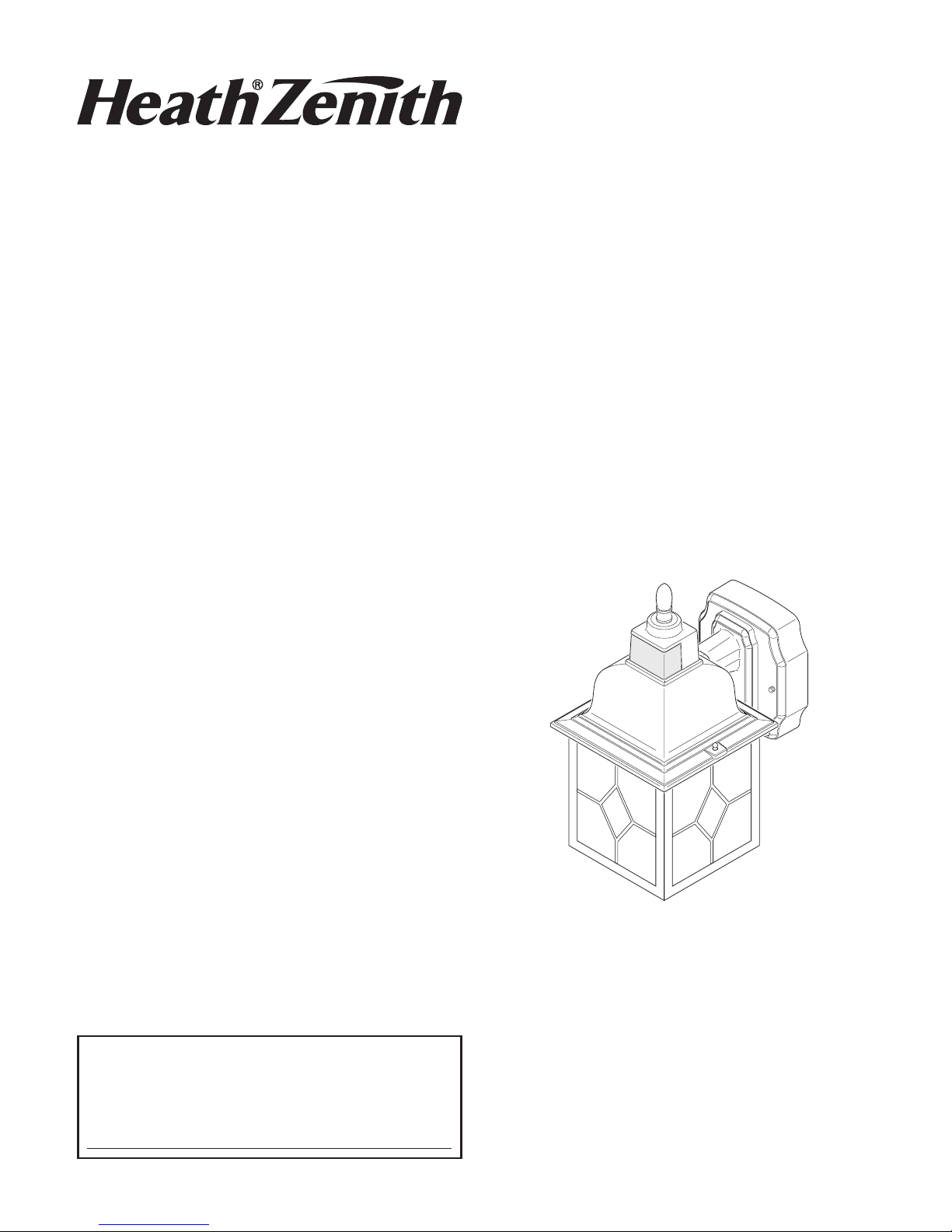
FEATURES
• Automatically comes on when motion is detected.
• Automatically turns light o.
• Dusk Accent lighting.
• Photocell keeps the light o during daylight
hours.
is package includes:
• Coach Light
• Mounting Bracket and Screws
• Wire Connectors
• Owner’s Manual
REQUIREMENTS
• e light control requires 120 volts AC.
• If you want to use Manual Mode, the control
must be wired through a switch.
• Some electrical codes require installation by
a qualied electrician. Please check the codes
in your area.
Model 4167
Before installation, record the model number listed inside the xture. Attach receipt
in case of possible warranty issues.
Model Number:
© 2013 HeathCo LLC 200471-02A
Installation and
Operating Instructions
DualBrite® Motion
Sensing Coach Light
Coach Light
Page 2
2
200471-02
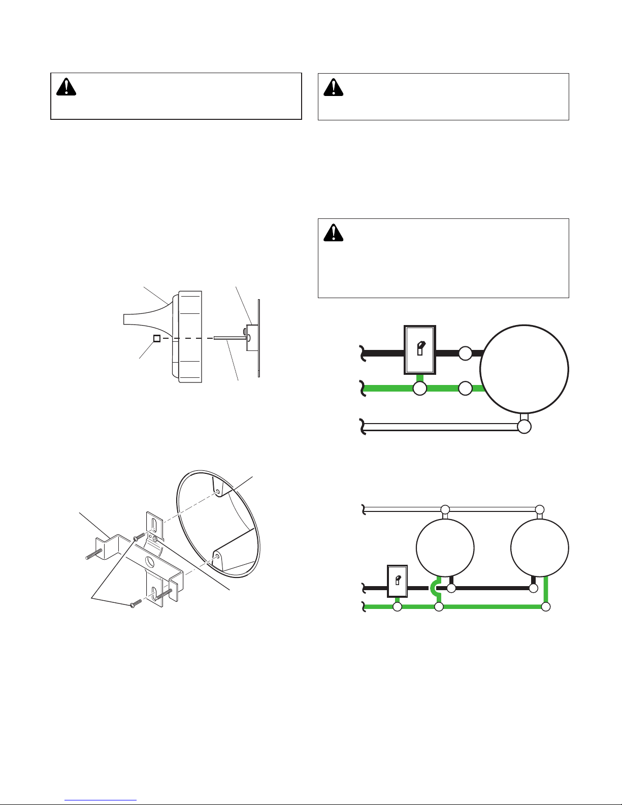
GND
WIRING
CAUTION: DO NOT connect the RED
wire unless you want to control other
lights from the motion sensor (see Op-
tional Wiring).
Note: All wiring must be run in accordance with
the National Electrical Code through conduit
or another acceptable means. Contact a quali-
ed electrician if there is any question as to the
suitability of the system.
WARNING: Turn power o at circuit
breaker or fuse.
One Motion Light
Two Motion Lights
Black
White
Green
or Bare
Light
Fixture
Black
White
Green
or Bare
Light
Fixture
Light
Fixture
Ground Screw
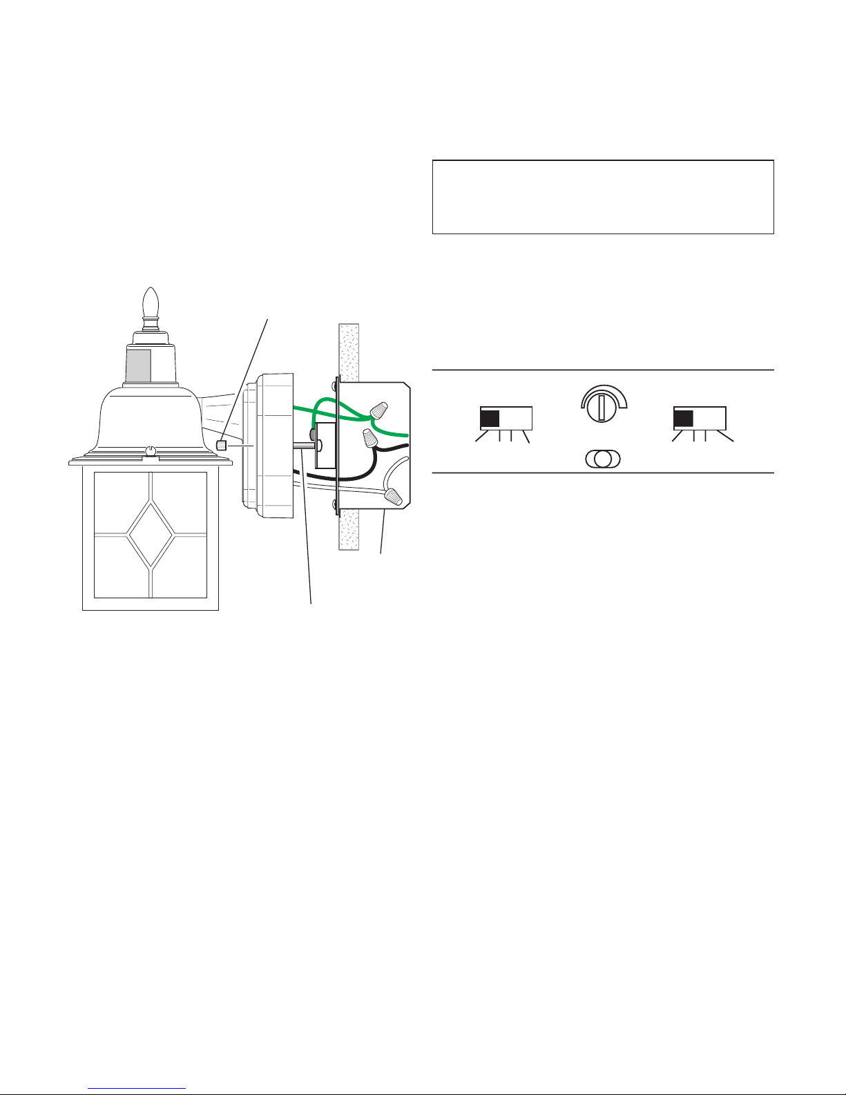
INSTALLATION
Bracket
Mounting
Screws
Junction
Box
Note: We recommend having an assistant help hold
the lantern assembly during the wiring process.
For best performance, mount the xture about 6
feet (1.8 m) above the ground.
1. Remove two decorative nuts.
2. Remove X-Bar.
3. Tighten mounting screws on X-Bar nger
tight.
4. Attach X-Bar to junction box.
WARNING: Turn power o at circuit
breaker or fuse.
X-Bar
Decorative Nut
Lantern Base
Lantern Mounting
Screw
X-Bar
Page 3
3
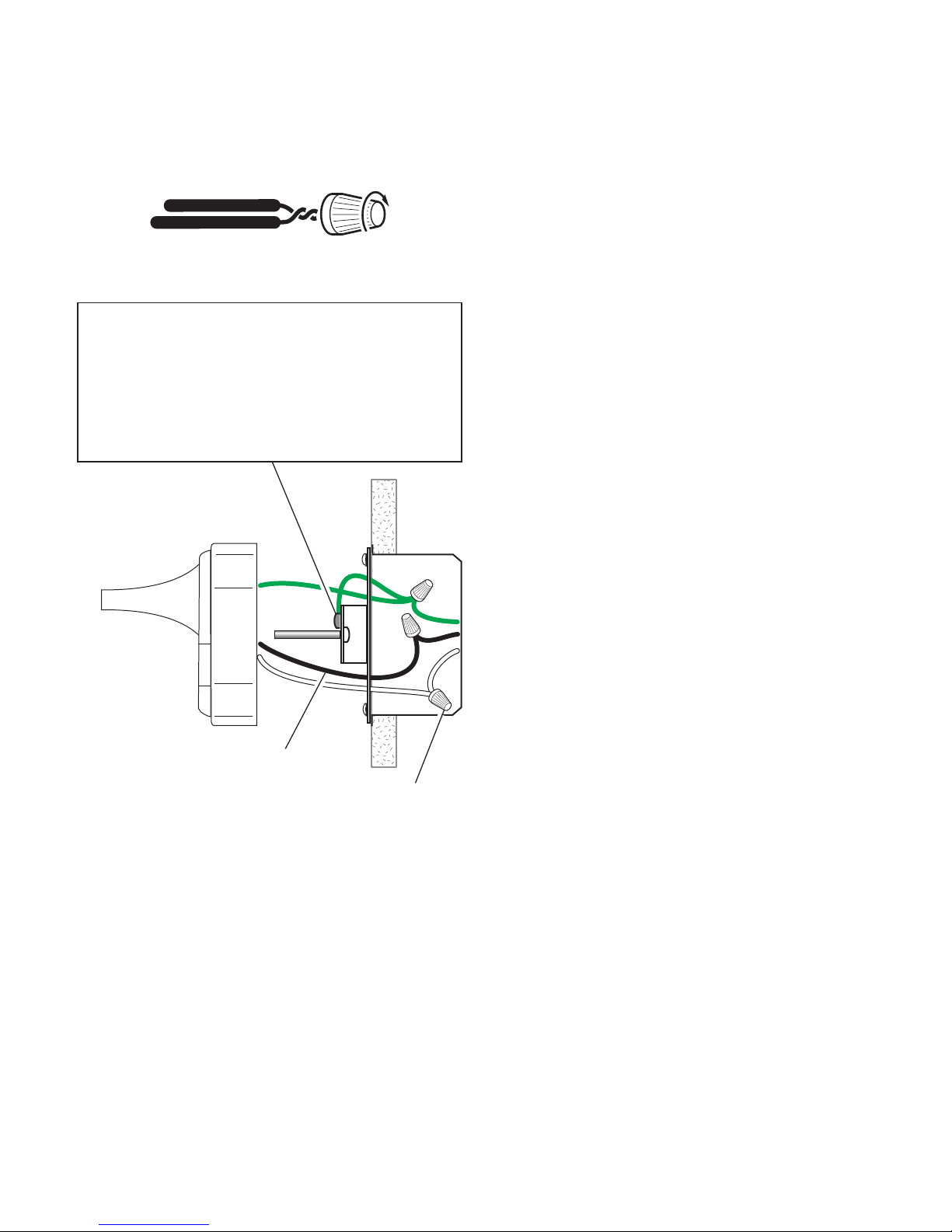
200471-02
Black to black
White to white
Recommended Grounding Method
Use a green ground “pigtail” (not provided) and
twist one end together with the bare xture wire
and the box ground wire. Secure with a wire
connector. Secure the other end of the “pigtail”
with the GND screw on the mounting plate.
Connect the xture wires to the wires in the junction box. Twist the wires together and secure with
wire connectors.
If you have metal junction box, you may not need
the green “pigtail”. If you are unsure about the
grounding method, consult your local building
code.
Page 4
4
200471-02
OPTIONAL WIRING
is xture is provided with a sensor rated for 360 Watts. Since the xture is only rated 100 Watts,
260 Watts of additional lighting may be controlled by this sensor.
When determining what a xture is rated for, do not simply look at the rating on the light bulb in
the xture. Look at the marking which species the maximum bulb wattage for which the xture
is suitable.
Once you have selected the xtures to be connected and determined their maximum ratings, add these
ratings up. For instance, if you have 3 xtures rated 100 Watts, 150 Watts, and 75 Watts respectively,
you have a total load of 325 Watts.
Wiring Diagram 1 – When wiring to control a standard light xture: Strip the motion sensor’s
red wire and connect to the standard light’s black wire. Connect all white wires together. Total xture
ratings must not exceed 360 Watts (3.0 A).
Wiring Diagram 2 – When wiring to control another motion sensing light xture (Master /
Slave): Strip the red wire in both light xtures. Connect the red wire of the controlling (master)
xture to the red and black wires of the controlled (slave) xture. Connect all white wires together.
Total xture ratings must not exceed 360 Watts (3.0 A).
Wiring Diagram 3 – When wiring so either motion light turns on the both motion lights
(Master / Master): Strip the red wire in both light xtures. Connect the red wire of one xture
to the red wire of the second xture. Note: In most installations, an additional wire (same gauge as
existing house wire) will have to be installed in the house to connect the two xtures as master /
master. Connect all white wires together and all black wires together. Total xture ratings must not
exceed 360 Watts (3.0 A).
Black
White
Green
or Bare
Light
Fixture
Light
Fixture
(Standard) Master Slave
Black
White
Green
or Bare
Light
Fixture
Light
Fixture
Red
Red
Wiring Diagram 1 Wiring Diagram 2
Wiring Diagram 3
Master Master
Black
White
Red
Green
or Bare
Light
Fixture
Light
Fixture
Page 5
5
200471-02
Junction
Box
FINAL ASSEMBLY
1. Push the wires into the junction box. Make
sure none of the wires get pinched.
2.
Slide the xture assembly onto the mounting
screws. Tighten decorative nuts removed in step
1 of Installation section securely against xture
base.
Mounting Screw
Decorative Nut
3. Install one medium base light bulb (100 Watt
maximum).
4. Caulk around xture base with silicone weather
sealant after all
Testing and Adjustments
are
complete.
TESTING AND ADJUSTMENTS
1. Turn on the circuit breaker and light
switch.
Note: Sensor has a 1 1/2 minute warm up period
before it will detect motion. When rst turned
on wait 1 1/2 minutes.
2. Set:
• ON-TIME switch to TEST
• DB® switch to OFF
• SENSITIVITY dial to Midway
3.
Walk through the coverage area noting where
you are when the lights turn on. In TEST mode,
light will stay on for 5 seconds after sensing
motion and then turn o.
TEST 1 5 10
MINUTE
OFF 3 6 DUSK TO
HOUR DAWN
– +
SEN
Page 6
6
200471-02
Note: When rst turned on wait about 1 1/2 minutes
for the circuitry to calibrate.
* resets to Auto Mode at dawn.
OPERATION
MANUAL MODE
4.
Adjust the SENSITIVITY to increase or
decrease the range as needed. Too much sensitivity may cause false triggering due to heat
sources in the coverage area (see Adjustment
of Coverage Area or Troubleshooting section).
5. Set the amount of ON-TIME you want the
light to stay on after motion is detected (1, 5,
or 10 minutes).
6. Set the DB® switch to o, 3 hours, 6
hours, or dusk-to-dawn.
Mode: On-Time Works: Day Night
Test
5 Seconds x x
Auto
1, 5, or 10
Minutes
x
Accent
3, 6 Hour,
To Dawn
x
Manual
To Dawn* x
... back on.
1 Second
OFF then...
Manual mode only works at
night because daylight returns
the sensor to AUTO.
Flip the light switch o for one
second then back on to toggle
between AUTO and MANUAL
MODE.
Manual mode works only with
the ON-TIME switch in the 1,
5, or 10 position.
30 ft.
(9.1 m)
6 ft.
(1.8 m)
180°
Maximum
Maximum Range Coverage Angle*
(Top View)
Least Sensitive Most Sensitive
e sensor is less sensitive to motion directly
towards it and more sensitive to motion across
coverage area.
Sensor
Motion Motion
Page 7

7
200471-02
ADJUSTMENT OF COVERAGE AREA
e sensor on this light xture detects “motion”
by the movement of heat across the coverage
area. However, following are examples of objects
that also produce heat and can cause the sensor
to trigger:
• Pools of Water • Air Conditioners
• Dryer Vents • Animals
• Heating Vents • Automobile Trac
If you suspect that a heat source of this type is
triggering the sensor, reduce the sensitivity.
SPECIFICATIONS
Range .................................................Up to 30 ft. (9.1 m) [varies with surrounding temperature]
Sensing Angle.....................................Up to 180°
Electrical Load ................................... Up to 100 Watt Maximum Incandescent
Bulb Type ...........................................Medium Base, Type “A”, 100 Watt Maximum
Sensor Capacity .................................. Up to 360 Watt (3.0 A) Maximum Tungsten
Power Requirements ...........................120 VAC, 60 Hz
Operating Modes ...............................TEST, AUTO, and MANUAL MODE
ON-Timer .......................................... 1, 5, 10 minutes
DB® Timer ........................... O, 3, 6 hours, dusk-to dawn
Test Timer .......................................... 5 Seconds
Manual Mode Timer .......................... Dusk-to-Dawn
MANUAL MODE
AUTO
TEST
ON-TIME Switch at 1, 5,
or 10 minutes
MODE SWITCHING SUMMARY
Flip light switch
o for one second
then back on*
* If you get confused while switching modes, turn
the power o for one minute, then back on. After
the calibration time the control will be in the AUTO
mode.
DualBrite® Dimmer Control
Light comes on half bright for selected time after
dusk (O, 3 hr., 6 hr., until dawn). Selecting OFF
disables this feature. e motion sensing features
will continue to work as described in this manual.
If motion is sensed, the light turns on full bright
for the ON-TIME (1, 5, or 10 minutes) then
returns to dim mode.
Page 8

8
200471-02
SYMPTOM POSSIBLE CAUSE SOLUTION
Lights will not
come on.
1. Light switch is turned o.
2. Light bulb is loose or burned out.
3. Fuse is blown or circuit breaker is turned o.
4. Daylight turn-o is in eect.
5. Sensor not detecting movement.
6. Incorrect circuit wiring, if this is a new installation.
1. Turn light switch on.
2. Check bulb and replace if burned out.
3. Replace fuse or turn circuit breaker on.
4. Recheck after dark.
5. Re-aim the sensor to cover desired area.
6. Verify wiring is correct.
Lights come on in
daylight.
1. Light control may be installed in a relatively dark
location.
2. Light control is in TEST.
1. e xture is operating normally under these
conditions.
2. Set control switch to 1, 5, or 10 minutes.
Lights come on for
no apparent reason.
1. Light control may be sensing small animals or automobile
trac.
2. Sensitivity is set too high.
1. Re-aim sensor. Reduce sensitivity.
2. Reduce sensitivity.
Lights stay on
continuously.
1. e sensor may be picking up a heat source like an air
vent, dryer vent, or brightly painted, heat-reective
surface.
2. Light control is in Manual Mode.
3. Light control is in DB® mode.
4. Sensitivity is set too high.
1. Re-aim sensor. Reduce sensitivity.
2. Switch to Auto.
3. Slide DB® switch to OFF position.
4. Reduce sensitivity.
Lights ash on
and o.
1. Light control is in the TEST mode and warming up.
2. Heat being reected from other objects may be aecting
the sensor.
1. Flashing is normal under these conditions.
2. Re-aim sensor. Reduce sensitivity.
TROUBLESHOOTING GUIDE
TECHNICAL SERVICE
Please call 1-800-858-8501 (English speaking only) for assistance before
returning product to store.
If you experience a problem, follow this guide. You may also want to visit our Web site at: www.
hzsupport.com. If the problem persists, call* for assistance at 1-800-858-8501 (English speaking
only), 8:00 AM to 5:00 PM CST (M-F). You may also write* to:
HeathCo LLC
P.O. Box 90045
Bowling Green, KY 42102-9045
ATTN: Technical Service
* If contacting Technical Service, please have the following information available: Model Number,
Date of Purchase, and Place of Purchase.
No Service Parts Available for this Product
Please keep your dated sales receipt, it is required for all warranty requests.
Page 9

9
200471-02
TWO YEAR LIMITED WARRANTY
is is a “Limited Warranty” which gives you specic legal rights. You may also have other rights
which vary from state to state or province to province.
For a period of two years from the date of purchase, any malfunction caused by factory defective
parts or workmanship will be corrected at no charge to you.
Not Covered - Repair service, adjustment and calibration due to misuse, abuse or negligence,
light bulbs, batteries, and other expendable items are not covered by this warranty. Unauthorized
service or modication of the product or of any furnished component will void this warranty in
its entirety. is warranty does not include reimbursement for inconvenience, installation, setup
time, loss of use, unauthorized service, or return shipping charges.
is warranty covers only HeathCo LLC assembled products and is not extended to other equipment and components that a customer uses in conjunction with our products.
THIS WARRANTY IS EXPRESSLY IN LIEU OF ALL OTHER WARRANTIES, EXPRESS
OR IMPLIED, INCLUDING ANY WARRANTY, REPRESENTATION OR CONDITION OF MERCHANT ABILITY OR THAT THE PRODUCTS ARE FIT FOR ANY
PARTICULAR PURPOSE OR USE, AND SPECIFICALLY IN LIEU OF ALL SPECIAL,
INDIRECT, INCIDENTAL, OR CONSEQUENTIAL DAMAGES.
REPAIR OR REPLACEMENT SHALL BE THE SOLE REMEDY OF THE CUSTOMER
AND THERE SHALL BE NO LIABILITY ON THE PART OF HEATHCO LLC FOR
ANY SPECIAL, INDIRECT, INCIDENTAL, OR CONSEQUENTIAL DAMAGES,
INCLUDING BUT NOT LIMITED TO ANY LOSS OF BUSINESS OR PROFITS,
WHETHER OR NOT FORESEEABLE. Some states or provinces do not allow the exclusion or limitation of incidental or consequential damages, so the above limitation or exclusion
may not apply to you.
Please keep your dated sales receipt, it is required for all warranty requests.
HeathCo LLC reserves the right to discontinue products and to change specications at any time
without incurring any obligation to incorporate new features in products previously sold.
Page 10

10
200471-02
© 2013 HeathCo LLC 200471-02 S
CARACTERÍSTICAS
• Se enciende automáticamente al detectar movimiento.
• Apaga la luz automáticamente.
• Iluminación ornamental de baja intensidad.
• La fotocélula mantiene la luz apagada durante
las horas diurnas.
Este paquete contiene:
• Luz de Coche
• Ménsula y tornillos para montaje
• Conectores de alambre
• Manual del propietario
REQUISITOS
• El control de luz requiere 120 VCA.
• Para usar el Modo Manual, conecte el control
con un interruptor.
• Algunos códigos requieren instalación por un
electricista calicado. Revise los códigos en su
área.
Modelo 4167
INSTRUCCIONES PARA SU
INSTALACIÓN Y FUNCIONAMIENTO
Antes de instalar, registre el número del modelo mostrado dentro del aparato. Fije el recibo
en caso posibles reclamos por la garantía.
Número del modelo:
DualBrite® Luces de
Coches Detectores de
Movimiento
Luz de Coche
Page 11

11
200471-02
INSTALACIÓN
Nota: Recomendamos tener un asistente que
ayude a sostener el conjunto del farol durante el
proceso de cableado.
Para un mejor funcionamiento, instale el aparato
a casi 1.8 m del suelo.
1. Quite dos tuercas decorativas.
2. Quite la banda “X” de montaje.
3. Ajuste los tornillos de montaje sobre el soporte
X-Bar sólo con los dedos.
4.
Monte el soporte X-Bar a la caja de empalme.
ADVERTENCIA: Desconecte la alimenta-
ción en el disyuntor o en el fusible.
GND
Tornillos del
tierra
Tornillo de
montaje
del soporte
La caja de
empalme
X-Bar
Tuerca decorativa
Base del farol
Tornillo de montaje
del farol
X-Bar
ADVERTENCIA: Desconecte la alimenta-
ción en el disyuntor o en el fusible.
CABLEADO
CUIDADO: NO conecte el cable ROJO
excepto que desee controlar otras luces
desde el detector de movimiento (Vea Co-
nexión Alterna).
Nota: Todo el cableado debe realizarse de acuerdo
con el Código Eléctrico Nacional usando tubería o
algún otro medio aceptable. Póngase en contacto
con un electricista calicado si tiene alguna
pregunta referente a la aptitud del sistema.
Luz de un movimiento
Luz de dos movimientos
Negro
Negro
Blanco
Blanco
Verde o
desnudo
Verde o
desnudo
Artefacto
de luz
Artefacto
de luz
Artefacto
de luz
Page 12

12
200471-02
Negro a negro
Blanco a blanco
Método recomendado de conexión a
tierra
Use un “cable exible” verde de tierra (no provisto) y tuerza un extremo con el cable desnudo
del aparato y con el cable de a tierra de la caja.
Asegúrelos con un conector de cables. Asegure
el otro extremo del “cable exible” con el tornillo
de a tierra de la placa de montaje.
Conecte los alambres del aparato a los alambres
de la caja de empalme. Tuerza juntos los alambres
y asegúrelos con conectores de alambre.
Si tiene una caja de empalme de metal, no necesita
el “cable exible”. Si no está seguro del método
de conexión a tierra, consulte con el código local
de construcción.
Page 13

13
200471-02
(Estándar)
Maestra Esclava
Rojo
Rojo
Esquema eléctrico 1 Esquema eléctrico 2
Esquema eléctrico 3
Maestra Maestra
Rojo
CONEXIÓN ALTERNA
Este aparato viene con un detector con una potencia de 360 Vatios. Puesto que este aparato tiene sólo
una potencia de 100 vatios, 260 vatios de luz adicional pueden ser controlados por este detector.
Cuando desee determinar la clasicación de un aparato no vea tan sólo la potencia de la lámpara. Mire
la indicación que especique el voltaje máximo de la lámpara que el aparato puede aceptar.
Una vez que ha escogido los aparatos que se conectarán y ha determinado sus máximas potencias,
súmelas. Por ejemplo, si tiene 3 aparatos de 100 , 150 y 75 Vatios respectivamente, usted tendrá un
total de 325 Vatios.
Esquema eléctrico 1 – Cuando prepare una conexión para controlar un aparato de luz estándar: Pele
el alambre rojo del detector de movimiento y conéctelo al alambre negro de la luz estándar. Conecte
todos los alambres blancos. La capacidad total no debe exceder los 360 Vatios (3.0 A).
Esquema eléctrico 2 – Cuando prepare una conexión para controlar otro aparato de luz detector
de movimiento: Pele el alambre rojo en ambos aparatos de luz. Conecte el alambre rojo del aparato
controlador (maestro) a los alambres rojo y negro del aparato controlado (esclavo). Conecte todos
los alambres blancos. La capacidad total no debe exceder los 360 Vatios (3.0 A).
Esquema eléctrico 3 – Cuando haga el cableado para que cualquier luz de movimiento prenda las
dos luces que detectan movimiento (Maestro / Maestro): Pele el conductor rojo de ambos aparatos
de luz. Conecte el conductor rojo de un aparato al conductor rojo del otro aparato. Nota: en la mayoría
de las instalaciones se deberá instalar un conductor adicional (del mismo calibre que el conductor
de la casa) dentro de la casa para conectar los dos aparatos como maestro / maestro. Conecte entre
si todos los alambres blancos y todos los alambres negros. La potencia nominal total del aparato no
debe ser más de 360 vatios (3.0 Amp).
Negro
Negro
Negro
Blanco
Blanco
Blanco
Verde o
desnudo
Verde o
desnudo
Verde o
desnudo
Artefacto
de luz
Artefacto
de luz
Artefacto
de luz
Artefacto
de luz
Artefacto
de luz
Artefacto
de luz
Page 14

14
200471-02
MONTAJE FINAL
1. Meta los alambres en la caja de empalme.
Asegúrese que ninguno de estos alambres
quede pellizcado.
2. Deslice el conjunto del aparato sobre los tornillos de montaje. Ajuste bien contra la base del
aparato las tuercas de montaje que se quitaron
en el paso 1 de la sección de Instalación.
3. Instale una base media para bombilla (100
vatios máximo).
4. Calafatee alrededor de la base del aparato con
un sellador de silicona contra la intemperie
después de completar todos los
Pruebas y
Ajustes
.
PRUEBAS Y AJUSTES
1. Conecte el disyuntor y el interruptor de la
luz.
Nota: El detector tiene un período de calentamiento de 1 1/2 minutos antes de detectar
movimiento. Cuando encienda por primera
vez, espere 1 1/2 minutos.
2. Ponga:
• El interruptor de TIEMPO en TEST
(PRUEBA)
• DB® interruptor para OFF (apagado)
• El cuadrante SENSITIVITY (de SENSIBILIDAD) en medio recorrido
3. Camine por el área de cobertura y note su
ubicación cuando se enciendan las luces. En
la fase TEST (PRUEBA), luego de detectar
movimiento, la luz quedará encendida por 5
segundos y luego se apagará.
La caja de
empalme
Tornillo de montaje
Tuerca decorativa
TEST 1 5 10
MINUTE
OFF 3 6 DUSK TO
HOUR DAWN
– +
SEN
Page 15

15
200471-02
Nota: Cuando encienda por primera vez, espere
1 1/2 minutos para que los circuitos se calibren.
*Se pone en Automático al amanecer.
OPERACIÓN
MODO MANUAL
4. Regule la SENSIBILIDAD para aumentar
o disminuir el alcance según lo que necesite.
Demasiada sensibilidad puede ocasionar falsas
alarmas debido a fuentes de calor en la zona
de cobertura (vea la sección Ajuste de la zona
de cobertura o la sección análisis de averías).
5. Fije el período de tiempo (ON-TIME) que la
luz debe quedarse prendida después de detectar
movimiento (1, 5 o 10 minutos).
6. Ponga el interruptor DB® en apagado
(o), 3 horas, 6 horas, o dusk-to-dawn (del
anochecer al amanecer).
...préndalo.
1 segundo
APAGADO
luego...
El modo manual funciona sólo
por la noche porque la luz del
día pone al detector en modo
AUTOMÁTICO.
Apague el interruptor por un
segundo y vuélvalo a prender para
conmutar entre MODO AUTOMÁTICO y MANUAL.
El modo manual funciona solamente con el interruptor de DURACIÓN DE TIEMPO en la
posición de 1, 5 o 10 minutos.
Modalidad: A tiempo: Trabaja:
Día Noche
Prueba
5 segundos x x
Automático
1, 5 o 10
minutos
x
Adorno
3, 6 hrs, hasta
el amanecer
x
Manual
Hasta el
amanecer*
x
9.1 m
1.8 m
180°
Alcance Máximo Ángulo de
Cobertura Máxima*
(Vista desde arriba)
Lo menos sensible Lo más sensible
Dentro del área de cobertura el detector es menos
sensible a movimientos en su dirección y más
sensible a movimientos transversales.
Detector
Movimiento Movimiento
Page 16

16
200471-02
RESUMEN DE LAS MODALIDADES
DEL INTERRUPTOR
REGULACIÓN DEL ÁREA DE
COBERTURA
El detector de este aparato de luz detecta “movimiento” debido al movimiento del calor a través
del área de cobertura. Sin embargo, a continuación
tiene ejemplos de objetos que también producir
calor y pueden hacer que el detector se active:
• Charcos de agua
• Acondicionadores de aire
• Ventosas de la secadora • Animales
• Ventosas de calefacción • Tráco automotor
Si sospecha que una fuente de calor de este tipo está
activando el detector, reduzca la sensibilidad.
ESPECIFICACIONES
Alcance ..................................................
Hasta 9.1 m. (varía con la temperatura del medio ambiente).
Ángulo de detección .............................. Hasta 180°
Carga Eléctrica ...................................... Hasta un máximo de 100 vatios de incandescente
Tipo de bombilla ................................... Casquillo mediano, tipo “A” de 100 vatios máximo
Capacidad del Detector .........................
Foco de tungsteno de hasta 360 vatios (3.0 A) como máximo
Requisitos de Energía ............................ 120 VCA, 60 Hz
Fases de Operación ................................ PRUEBA, AUTOMÁTICO y MODO MANUAL
Temporizador de duración
(del encendido) ...................................... 1, 5 o 10 minutos
Temporizador de DB® ............. Apagado, 3, 6 horas, del atardecer al amanecer
Temporizador de prueba ........................ 5 segundos
Temporizador de la fase manual ............ Del atardecer al amanecer
Mueva el interruptor de
tiempo (ON-TIME) a 1, 5 o
10 minutos
Apague el interruptor por
un segundo y préndalo de
nuevo*
PRUEBA
AUTOM.
MODO
MANUAL
* Si se confunde mientras cambia de fases, apague
la electricidad por un minuto y préndala de nuevo.
Después del tiempo de calibración el control estará
en fase AUTO(MÁTICA).
Luz de Adorno (DualBrite®)
La luz se prende con media brillantez por el
tiempo escogido después del atardecer (apagado,
3 hr., 6 hrs., hasta el amanecer). Si escoge OFF
(APAGADO) deshabilita esta función. Las
funciones que detectan movimiento continuarán
funcionando como se describen en este manual.
Si detecta movimiento, la luz se prende con todo
su resplandor por el tiempo de duración o de
ON-TIME (1, 5 o 10 minutos) y luego regresa
a media luz.
Page 17

17
200471-02
GUÍA DE INVESTIGACIÓN DE AVERÍAS
SÍNTOMA POSIBLE CAUSA SOLUCIÓN
Las luces no se prenden. 1. El interruptor de luz está apagado.
2. La bombilla está oja o quemada.
3. El fusible está quemado o el cortacircuitos está
apagado.
4. La modalidad de apagado durante el día está en
efecto.
5. El sensor no detecta el movimiento.
6. Alambrado incorrecto, si ésta es una nueva instalación.
1. Encienda el interruptor de luz.
2. Revise la lámpara y cámbiela si está quemada.
3. Cambie el fusible encienda el disyuntor.
4. Revíselo después del anochecer.
5. Apunte de nuevo el detector para cubrir las áreas
deseadas.
6. Verique que el cableado esté correcto.
Las luces se prenden
durante el día.
1. El control de luz puede estar instalado en un lugar
relativamente obscuro.
2. El control de luz está en fase de Prueba.
1. El aparato está funcionando normalmente bajo estas
condiciones.
2. Fije el interruptor de control a 1, 5 o 10 minutos.
Las luces se prenden sin
ninguna razón aparente.
1. El control de luz puede estar detectando animales
pequeños o el trásito de automóviles.
2. La Sensibilidad es demasiado alta.
1. Reposicione el detector. Reduzca la sensibilidad.
2. Reduzca la sensibilidad.
Las luces se quedan prendidas continuamente.
1. El sensor puede detectar fuentes de calor, como
ductos de calefacción y de aire acondicionado, o
supercies resplandecientes que reejan la luz.
2. El control de luz está en fase Manual.
3.
El control de luz está en la modalidad DB®.
4. La Sensibilidad es demasiado alta.
1. Reposicione el detector. Reduzca la sensibilidad.
2. Cámbiela a Auto.
3. Deslice el interruptor DB® a la posición de
apagado (o).
4. Reduzca la sensibilidad.
La luce se prenden y se
apagan.
1. El control de luz está en fase de Prueba y calentándose.
2. El calor que se reeja de otros objetos pueden
estar afectando al detector.
1. El prenderse y apagarse es normal bajo estas condiciones.
2. Reposicione el detector. Reduzca la sensibilidad.
SERVICIO TÉCNICO
Favor de llamar al 1-800-858-8501 (sólo para hablar en inglés) para pedir ayuda
antes de devolver el producto a la tienda.
Si tiene algún problema, siga esta guía. Usted puede también visitar nuestro sitio Web: www.hzsupport.com. Si el problema continúa, llame al 1-800-858-8501 (sólo para hablar en inglés), de 8:00
AM a 5:00 PM CST (L-V). Usted puede también escribir a:
HeathCo LLC
P.O. Box 90045
Bowling Green, KY 42102-9045
ATTN: Technical Service (Servicio Técnico)
* Si se llama al Servicio Técnico, por favor tener lista la siguiente información: Número de Modelo,
Fecha de compra y Lugar de compra.
No hay piezas de servicio disponibles para este producto.
Por favor guarde su recibo de venta fechado; se lo requiere para cualquier solicitud de garantía.
Page 18

18
200471-02
GARANTÍA LIMITADA A 2 AÑOS
Esta es una “Garantía Limitada” que le da a Ud. derechos legales especícos. Usted puede también
tener otros derechos que varían de estado a estado o de provincia a provincia.
Por un período de 2 años desde la fecha de compra, cualquier mal funcionamiento ocasionado
por partes defectuosas de fábrica o mano de obra será corregido sin cargo para Ud.
No cubierto - Servicio de reparación, ajuste y calibración debido al mal uso, abuso o negligencia,
bombillas, baterías, u otras partes fungibles no están cubiertas por esta garantía. Los Servicios no
autorizados o modicaciones del producto o de cualquier componente que se provee invalidarán
esta garantía en su totalidad. Esta garantía no incluye reembolso por inconveniencia, instalación,
tiempo de instalación, perdida de uso, servicio no autorizado, o costos de transporte de retorno.
Esta garantía cubre solamente los productos ensamblados por HeathCo LLC y no se extiende a
otros equipos o componentes que el consumidor usa junto con nuestros productos.
ESTA GARANTÍA ESTÁ EXPRESAMENTE EN LUGAR DE OTRAS GARANTÍAS,
EXPRESADAS O SOBREENTENDIDAS, INCLUYENDO CUALQUIER GARANTÍA,
REPRESENTACIÓN O CONDICIÓN DE COMERCIABILIDAD O QUE LOS PRODUCTOS SE ADAPTEN PARA CUALQUIER PROPÓSITO O USO EN PARTICULAR, Y ESPECIFICAMENTE EN LUGAR DE TODOS LOS DAÑOS ESPECIALES,
INDIRECTOS, INCIDENTALES Y CONSECUENTES.
LA REPARACIÓN O EL REEMPLAZO DEBERÍA SER LA ÚNICA SOLUCIÓN DEL
CLIENTE Y NO HABRÁ RESPONSABILIDAD POR PARTE DE HEATHCO LLC POR
CUALQUIER DAÑO ESPECIAL, INDIRECTO, INCIDENTAL O CONSECUENTE,
INCLUIDOS PERO NO LIMITADOS A CUALQUIER PÉRDIDA DE NEGOCIO O
GANACIAS SEAN O NO PREVISIBLES. Algunos estados o provincias no permiten la exclusión o limitación de daños incidentales o consecuentes, de modo que la limitación o exclusión
arriba indicada puede que no se aplique a Ud.
Por favor guarde su recibo de venta fechado; se lo requiere para cualquier solicitud de garantía.
HeathCo LLC se reserva el derecho de descontinuar productos y de cambiar especicaciones a cualquier momento sin incurrir en ninguna obligación de tener que incorporar nuevas características en
los productos vendidos con anterioridad.
Page 19

19
200471-02
Lanterne de carrosse
© 2013 HeathCo LLC 200471-02 F
CARACTÉRISTIQUES
• S’allume automatiquement lors de la détection
d’un mouvement.
• S’éteint automatiquement.
• Éclairage d'accentuation de crépuscule.
• Cellule photo-électrique qui garde l’éclairage
fermé pendant la journée.
Cet emballage contient:
• Lanterne de carrosse
• Vis et xation de montage
• Connecteurs de l
• Manuel du propriétaire
EXIGENCES
• La commande d’éclairage exige du courant
120 V c.a.
• Pour utiliser le mode de fonctionnement manuel,
la commande d’éclairage doit être reliée à un
interrupteur.
• Dans certaines localités, le code de l’électri-
cité exige que l’installation soit conée à un
électricien qualié. Veuillez vérier les codes
en vigueur dans votre région.
Avant l’installation, inscrivez ici le numéro
de modèle qui se trouve à l’intérieur de
l’appareil. Joignez-y le reçu d’achat pour
les réclamations sous garantie.
Numéro de modèle :
Instructions d'installation
et mode d'emploi
Lanterne de voiture
DualBrite
MD
à détecteur
de mouvement
Modèle 4167
Page 20

20
200471-02
INSTALLATION
Pour un rendement optimal, montez le luminaire
à environ 1,8 m au-dessus du sol.
1. Retirez les deux écrous décoratifs.
2. Enlevez la barre-X.
3. Serrez à la main les vis de la croix en « X ».
4. Fixez la barre-X à la boîte de jonction.
Note : Il est recommandé de demander à une
autre personne de tenir la lanterne pendant le
passage des ls.
CÂBLAGE
AVERTISSEMENT: NE PAS raccorder
le l ROUGE à moins que vous ne vouliez
commander d’autres luminaires au moyen
du détecteur de mouvement (voir Câblage
Facultatif).
Note : Le câblage doit être conforme aux exigences
du Code national de l’électricité et être installé
dans des canalisations ou autres dispositifs acceptables. Si vous avez des doutes concernant la
convenance du système, consultez un électricien
reconnu.
MISE EN GARDE : Coupez l’alimentation
au disjoncteur ou au fusible.
Une lanterne à détecteur de mouvement
Deux lanternes à détecteur de mouvement
Noir
Blanc
Vert ou
dénudé
Luminaire
Luminaire Luminaire
Noir
Blanc
Vert ou
dénudé
GND
Vis de mise
à la terre
Vis de
montage
du support
Boîte de
jonction
Barre-X
Écrou décoratif
Socle de la lanterne
Vis de montage
de la lanterne
Barre-X
Page 21

21
200471-02
Branchez les ls du luminaire aux ls dans la boîte
de raccordement. Torsadez ces ls ensemble, puis
ajoutez-y un connecteur de ls.
Si la boîte de jonction est en métal, vous pourriez
nécessiter une «queue de cochon» verte. Si vous
avez des doutes sur la méthode de mise à la terre,
consultez votre code du bâtiment.
noir/noir
blanc/blanc
Méthode de mise à la terre
recommandée
Utilisez une «queue de cochon» verte (non
fournie) et torsadez-en une extrémité avec le
l nu du luminaire et le l de terre de la boîte
de jonction. Utilisez un serre-ls. Fixez l'autre
extrémité de la «queue de cochon» avec la vis de
terre (GND) sur la plaque de montage.
Page 22

22
200471-02
CÂBLAGE FACULTATIF
Ce luminaire est pourvu d'un capteur de 360 W. Comme ce luminaire ne consomme que 100 W, le
capteur peut commander 260 W d’éclairage supplémentaire.
Lorsque vous déterminez l'intensité que peut supporter un luminaire, ne vous contentez pas de simplement lire l'intensité indiquée sur l'ampoule. Recherchez l'étiquette indiquant le wattage d'ampoule
maximal de l'appareil.
Une fois que vous avez choisi les luminaires à raccorder et déterminé leur intensité maximale respective, additionnez les intensités. Par exemple, si vous avex 3 appareils dont l'intensité est 100 Watts,
150 Watts et 75 Watts respectivement, la charge totale est 325 Watts.
Diagramme de câblage 1 – Câblage d’un luminaire standard : dénudez le l rouge du détec-
teur de mouvement et raccordez-le au l noir du luminaire standard. Raccordez tous les ls blancs
ensemble. L'intensité maximale ne noit pas dépasser 360 Watts (3,0 A).
Diagramme de câblage 2 – Câblage d’un autre luminaire à détecteur de mouvement (Maître
/ Satellite) : dénudez le l rouge des deux luminaires. Branchez le l rouge du luminaire de com-
mande (maître) aux ls rouge et noir du luminaire commandé (satellite). Branchez tous les ls blancs
ensemble. La consommation totale des luminaires ne doit pas être supérieure à 360 Watts (3,0 A).
Diagramme de câblage 3 – Câblage de sorte que l’une ou l’autre des commandes déclenche les deux luminaires (Maître / Maître) : dénudez le l rouge des deux luminaires. Branchez
le l rouge d’un luminaire au l rouge du second luminaire. Note : Dans la plupart des cas, un l
supplémentaire (de même calibre que le l de la résidence) doit être installé pour raccorder les deux
luminaires en conguration « principal / principal ». Raccordez tous les ls blancs ensemble, puis
faites de même avec tous les ls noirs. La consommation totale des luminaires ne doit pas être supérieure à 360 Watts (3,0 A).
Maître Satellite
Maître Maître
Diagramme de câblage 1
Noir
Noir
Noir
Blanc
Blanc
Blanc
Vert ou
dénudé
Vert ou
dénudé
Vert ou
dénudé
Diagramme de câblage 2
(Standard)
Luminaire LuminaireLuminaire Luminaire
Rouge
Rouge
Diagramme de câblage 3
Luminaire Luminaire
Rouge
Page 23

23
200471-02
ASSEMBLAGE FINAL
1. Repoussez les ls dans la boîte de raccordement.
Assurez-vous qu’aucun des ls n’est pincé.
2. Faites glisser le socle du luminaire sur les vis
de montage. Serrez solidement sur le socle les
écrous décoratifs retirés à l’étape 1, à la section
Installation.
3. Installez une ampoule à culot moyen (maximum de 100 W).
4. Appliquer un scellant à la silicone tout autour
de la base du luminaire, une fois tous les
Essais
et Réglages
terminés.
ESSAIS ET RÉGLAGES
1. Ré-enclenchez le disjoncteur puis ouvrez
l’interrupteur.
Note : Le capteur exige 1
1
/2 minute avant de
détecter les mouvements. Lors de la première
mise sous tension, attendez 1 1/2 minute.
2. Réglages :
• Commutateur ON-TIME à TEST
• L’interrupteur DBMD est en position
OFF (ARRÊT)
• Cadran SENSITIVITY au milieu
3. Déplacez-vous dans la zone de couverture
en notant l’endroit où vous trouvez lorsque
l’éclairage s’allume. En mode TEST, l’éclairage
demeure allumé pendant 5 secondes après
qu’un mouvement est détecté.
Boîte de
jonction
Vis de montage
Écrou décoratif
TEST 1 5 10
MINUTE
OFF 3 6 DUSK TO
HOUR DAWN
– +
SEN
Page 24

24
200471-02
FONCTIONNEMENT
* Revient au mode automatique au lever du soleil.
Note : Après mise en circuit, attendre enron
1 1/2 minute pour que l’étalonnage du circuit
soit complété.
PRIORITÉ MANUELLE
4. Régler la sensibilité (SENSITIVITY) selon
les besoins. Une trop grande sensibilité pourrait
entraîner des déclenchements intempestifs attribuables à des sources de chaleur dans la zone
de couverture (consultez les sections
Réglage de
la zone de couverture ou Guide de Dépannage
).
5.
Réglez la période (ON-TIME) pendant laquelle
vous souhaitez que l’éclairage fonctionne après détection d’un mouvement (1, 5 ou 10 minutes).
6. Placer le commutateur DBMD à fermé
(o), 3 heures, 6 heures ou crépuscule-aurore
(dusk-to-dawn).
Mode: Temps en circuit:
En fonction:
jour nuit
Essai
5 secondes x x
Auto
1, 5 ou 10 min. x
Accentuation
3, 6 h jusqu’à l’aurore x
Manuel
au choix, amanecer* x
... à nouveau
en circuit
hors circuit
pendant 1
seconde, puis ...
Le mode manuel ne fonctionne que la nuit parce que
la lumière du jour remet le
capteur en mode AUTO.
Mettre l’interrupteur hors
circuit pendant une seconde,
plus en circuit pour alterner
entre les modes AUTO et
MANUEL.
Le mode manuel ne fonctionne que lorsque l’interrupteur ON-TIME est aux
positions 1, 5 ou 10.
30 ft.
(9.1 m)
6 ft.
(1.8 m)
180°
Angle de
Portée maximale couverture maximale
(Vue en plongée)
Le capteur est moins sensible aux déplacements
directement vers lui; il est plus sensible aux mouvements traversant la zone de couverture.
Capteur
Le moins sensible Le plus sensible
Mouvement Mouvement
Page 25

25
200471-02
RÉGLAGE DE LA ZONE DE
COUVERTURE
Le capteur de ce luminaire détecte les mouvements
lors des « déplacements de chaleur » dans la zone
de couverture. Quoi qu’il en soit, les objets suivants
produisent aussi de la chaleur et peuvent entraîner
le déclenchement du capteur :
• Piscine • Appareil de climatisation
• Évent de sécheuse • Animaux
• Évent de ventilation • Circulation automobile
Si vous croyez qu’une source de chaleur de ce type
déclenche le capteur, réduisez sa sensibilité.
FICHE TECHNIQUE
Portée ..........................................................Jusqu’à 9,1 m [varie selon la température environnante]
Angle de détection .......................................
Jusqu’à
180°
Charge électrique .........................................Jusqu’à une ampoule incandescentes, pour un maximum de
100 Watt
Type d’ampoule ...........................................Culot moyen, type A, 100 W maximum
Capacité du détecteur ..................................Tungstène jusqu'à 360 watts (3,0 A) maximum
Courant requis ............................................. 120 V c.a., 60 Hz
Modes de fonctionnement ........................... ESSAI, AUTO et MANUEL
Minuterie de fonctionnement ......................1, 5 ou 10 minutes
Minuterie de DBMD .......................Fermé, 3, 6 heures, crépuscule-aurore
Minuterie d’essai ..........................................5 secondes
Minuterie du mode MANUEL...................
Du coucher au lever du soleil
Placer l’interrupteur ONTIME à 1, 5 ou 10 minutes
Mettre l’interrupteur
hors circuit pendant
une seconde, puis le
remettre en circuit
* Si vous ne savez plus dans quel mode se trouve
l’appareil, couper l’alimentation pendant une minute puis la rétablir. Après le temps d’étalonnage,
la commande reviendra au mode AUTO.
Minuterie DualBrite
MD
La lumière s'allume à mi-intensité pour le temps
choisi après le crépuscule [O (hors circuit) 3h,
6h, jusqu'à l'aurore]. Pour désactiver cette fonction, placez le commutateur à OFF. La fonction
de détection de mouvement continuera toutefois
de fonctionner tel que décrit dans ce guide. Si
un mouvement est détecté, la lumière s'allume
à pleine intensité pour le temps (ON-TIME)
choisi (1, 5 ou 10 minutes), puis revient en mode
faible intensité.
PRIORITÉ MANUELLE
AUTO
TEST
RÉSUMÉ DU MODE DE
COMMUTATION
Page 26

26
200471-02
SYMPTÔME CAUSE POSSIBLE SOLUTION
L’éclairage ne
s’allume pas.
1. L’interrupteur d’éclairage est hors tension.
2. L’ampoule est lâche ou grillée.
3. Le fusible a sauté ou le disjoncteur a été
déclenché.
4. La fonction de fermeture pendant le jour est
activée.
5. Capteur, sans détection de mouvement.
6. Mauvais câblage du circuit, dans le cas d’une
nouvelle installation.
1. Mettre l’interrupteur sous tension.
2. Vérier l’ampoule et la remplacer si elle est grillée.
3. Remplacer le fusible ou ré-enclencher le disjoncteur.
4. Essayer de nouveau après la tombée de la nuit.
5. Réorienter le détecteur pour obtenir la couverture désirée.
6. S’assurer que le câblage est approprié.
L’éclairage s’allume
en plein jour.
1. La commande peut être installée dans un endroit
relativement sombre.
2. La commande d’éclairage est en mode essai.
1. Le luminaire fonctionne normalement dans de telles
conditions.
2. Réglez le commutateur de commande à 1, 5 ou 10
minutes.
L’éclairage s’allume
sans raison
apparente.
1. Le capteur détecte peut-être de petits animaux
ou la circulation automobile.
2. Le réglage de portée est trop élevé.
1. Réorientez le détecteur. Réduisez la portée.
2. Réduisez la portée.
L’éclairage
demeure allumé
continuellement.
1. Le capteur peut percevoir une source de chaleur
comme une sortie d’air, un évent de sécheuse
ou une surface de couleur claire rééchissant la
chaleur.
2. La commande d’éclairage est en mode Manuel.
3. La commande d’éclairage est en mode
DBMD.
4. Le réglage de portée est trop élevé.
1. Réorientez le détecteur. Réduisez la portée.
2. Faites-la passer au mode Auto.
3. Faire glisser le commutateur DBMD en position
OFF.
4. Réduisez la portée.
L’éclairage clignote. 1. La commande d’éclairage est en mode essai et se
réchaue.
2. La chaleur qui est rééchie par d’autres objets
peut aecter la commande d’éclairage.
1. Le clignotement est normal dans ces deux cas.
2. Réorientez le détecteur. Réduisez la portée.
GUIDE DE DÉPANNAGE
SERVICE TECHNIQUE
Veuillez faire le 1 800 858-8501 (service en anglais seulement) pour obtenir de
l’aide avant de retourner l’article au magasin.
En cas de problème, suivez ce guide. Vous pouvez aussi visiter notre site Web à www.hzsupport.com.
Si le problème persiste, composez* le 1 800 858-8501 (service en anglais seulement), entre 8 h 00 et 17
h 00, HNC, du lundi au vendredi. Vous pouvez aussi écrire au :
HeathCo LLC
P.O. Box 90045
Bowling Green, KY 42102-9045
ATTN: Technical Service (Service technique)
* Lors d’un appel au service technique, veuillez avoir les renseignements suivants à portée de main :
numéro du modèle, date d’achat et endroit de l’achat.
Aucune pièce de rechange n’est disponible pour ce produit.
Veuillez conserver le reçu portant la date d'achat; vous en aurez besoin pour toutes vos demandes
liées à la garantie.
Page 27

27
200471-02
GARANTIE LIMITÉE DE 2 ANS
Il s’agit d’une « Garantie limitée » qui vous confère des droits juridiques spéciques. Vous pouvez
également jouir d’autres droits, variables d’une province à l’autre.
Pendant une période de 2 ans à compter de la date d’achat, toute anomalie de fonctionnement
imputable à un vice de matériau ou de main-d’oeuvre sera corrigée gratuitement.
Exclusions de la garantie - Réparations, réglage et calibrage dus à une mauvaise utilisation, un
mauvais traitement ou à la négligence. Les ampoules, les piles et des autres articles non durables
ne sont pas couverts par cette garantie. Le service non autorisé ou la modication du produit ou
d’un ou l’autre de ses composants fournis invalidera totalement la présente garantie. Cette garantie
n’inclut pas le remboursement pour le dérangement, l’installation, le réglage, la perte d’utilisation,
le service non autorisé ou les frais d’expédition pour le renvoi de la marchandise.
La garantie ne couvre que les produits assemblés HeathCo LLC et ne s’étend pas aux autres
équipements et composants que le client pourrait utiliser conjointement avec nos produits.
CETTE GARANTIE TIENT EXPRESSÉMENT LIEU DE TOUTES AUTRES GARANTIES, EXPLICITES OU IMPLICITES, Y COMPRIS DE TOUTE GARANTIE
DE REPRÉSENTATION OU DE CONDITION DE CONVENANCE À LA COMMERCIALISATION OU À L’EFFET QUE LES PRODUITS CONVIENNENT À UN
BUT OU À UNE UTILISATION PARTICULIÈRE, ET SPÉCIFIQUEMENT DE TOUS
DOMMAGES SPÉCIAUX, DIRECTS, INDIRECTS OU SECONDAIRES.
LE REMPLACEMENT OU LA RÉPARATION CONSTITUENT LE SEUL RECOURS
DU CLIENT ET HEATHCO LLC NE POURRA ÊTRE TENUE RESPONSABLE DE
TOUS DOMMAGES SPÉCIAUX, DIRECTS, INDIRECTS OU SECONDAIRES, Y
COMPRIS, SANS S’Y LIMITER, LES PERTES COMMERCIALES ET PERTES DE
PROFIT, QU’ELLES SOIENT PRÉVISIBLES OU NON. Certaines provinces n’autorisent pas
l’exclusion ou la limitation des dommages indirects ou secondaires, et la limitation ou l’exclusion
ci-dessus pourrait ne pas s’appliquer à vous.
Veuillez conserver le reçu portant la date d'achat; vous en aurez besoin pour toutes vos demandes liées à la garantie.
HeathCo LLC se réserve le doit d’abandonner tout produit et d’en changer les spécications, en
tout temps et sans contracter quelque obligation que ce soit quant à l’incorporation de nouvelles
caractéristiques aux produits déjà vendus.
Page 28

28
200471-02
Staple Purchase Receipt Here
Engrape aquí el recibo de compra
Agrafez le reçu d’achat ici
PLEASE KEEP YOUR DATED SALES RECEIPT,
IT IS REQUIRED FOR ALL WARRANTY REQUESTS.
POR FAVOR GUARDE SU RECIBO DE VENTA FECHADO; SE LO
REQUIERE PARA CUALQUIER SOLICITUD DE GARANTÍA.
VEUILLEZ CONSERVER LE REÇU PORTANT LA DATE D'ACHAT;
VOUS EN AUREZ BESOIN POUR TOUTES VOS DEMANDES LIÉES À
LA GARANTIE.
Purchase Information
Información de la compra
Renseignements d’achat
Model #: ________________________ Date of Purchase: _______________________
Nº de modelo / N° de modèle Fecha de compra / Date d’achat
 Loading...