

Page 1
© 2016 HeathCo LLC 208949-01A
INSTALLATION AND OPERATING
INSTRUCTIONS
SAFETY INFORMATION ......................................2
PREPARATION ...............................................2
HARDWARE CONTENTS ......................................2
LIGHT FIXTURE INSTALLATION ...............................3
WIRING THE LIGHT FIXTURE .................................4
OPTIONAL WIRING ..........................................5
MOUNTING THE LIGHT FIXTURE .............................6
TESTING AND ADJUSTMENTS ................................6
CARE AND MAINTENANCE ...................................7
TROUBLESHOOTING GUIDE ..................................8
SPECIFICATIONS .............................................8
TECHNICAL SERVICE .........................................9
TWO YEAR LIMITED WARRANTY .............................9
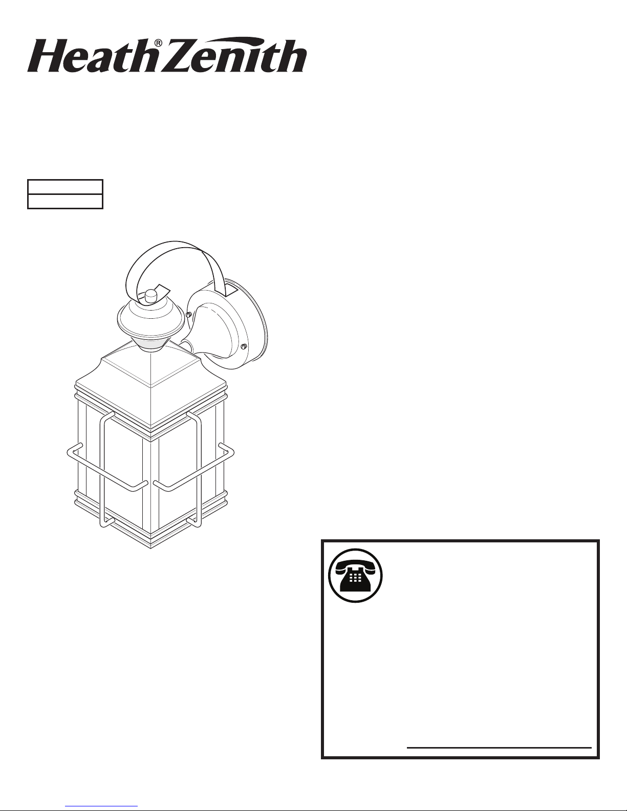
Motion Decorative Light
Questions?
Please refer to the troubleshooting guide in this manual
or call our technical service department (English speaking only) at 1-800-858-8501, 8:00 a.m. - 5:00 p.m., CST,
Monday - Friday before returning to your retailer.
Keep this manual for future reference.
ATTACH YOUR RECEIPT HERE
Receipt is required for all warranty requests.
Purchase Date
* BulbSaver - Light comes on dim and gradually increases to
full brightness. When the light turns o it will gradually dim to
half-bright, pause, and then will continue dimming until the
light turns o.
For a description of the DualBrite® technology, see page 7.
Model
4144
DualBrite® Motion Sensing
Decorative Light
Page 2
2 208949-01
SAFETY INFORMATION
Please read and understand this entire manual before attempting to assemble, operate, or install the product.
is light xture requires 120-volts AC. All wiring must be
in accordance with the National Electrical Code (Canadian
Electrical Code in Canada). Some local electrical codes
require installation by a qualied electrician.
WARNING
• Turn power o at circuit breaker or fuse when
wiring xture or replacing bulbs. Place tape over
circuit breaker switch and verify power is o at
the xture.
CAUTION
• Do not cut any wires that have factory installed
wire connectors or remove the wire connectors.
PREPARATION
Before beginning installation of product, make sure all parts
are present. Compare parts with hardware contents list. If
any part is missing or damaged, do not attempt to assemble,
install, or operate the product.
Tools Required for Assembly (not included): Phillips and
athead screwdrivers, pliers, wire strippers/cutters, multimeter, electrical tape, silicone sealant, safety glasses, work
gloves, and ladder
• For easy installation and to operate the light using Manual
mode, replace an existing light xture operated by a wall
switch.
• Do not connect to dimmers or timers.
• For best performance, mount xture about 6 feet (1.8 m)
above the ground.
Estimated Installation Time: 30 minutes
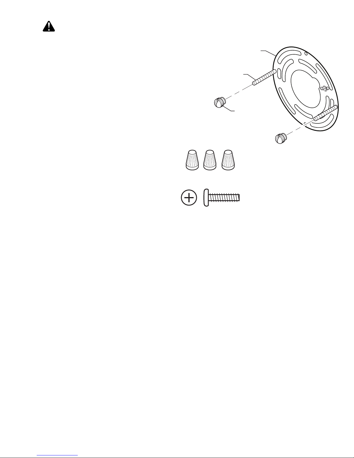
3x – Wire Connectors
2x – Mounting
Bracket Screw
A - (1x) Mounting Bracket
B - (2x) Fixture Mounting
Screws
C - (2x) Decorative Nut
(This assembly is attached to
the rear of the lantern canopy.)
HARDWARE CONTENTS
Note: Illustrations may vary from actual unit.
A
B
C
Page 3
3208949-01
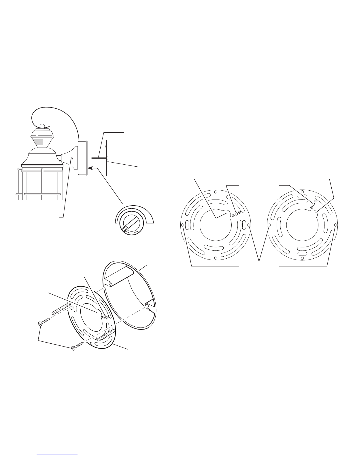
Wire Path
Ground Screw
Mounting
Plate
LIGHT FIXTURE INSTALLATION
For best performance, mount the xture about 6 feet (1.8m)
above the ground.
1. Remove two decorative nuts.
2. Remove mounting plate.
3. Tighten mounting screws nger tight.
4. Set sensitivity control on back of xture to MIN
position.
5. Attach mounting plate to junction box.
Decorative Nut
Mounting Screw
Bracket
Mounting
Screws
Mounting Plate
Junction
Box
Note: We recommend having an assistant help hold the
lantern assembly during the wiring process.
is xture comes with a universal mounting bracket. It is
pre-assembled on the xture to t the majority of junction
box applications.
If the slots on the mounting plate do not line up with the
junction box screw holes, follow these steps:
1. Remove the xture mounting screws from the mounting
plate. Note: Do not remove the ground screw.
2. Attach ground wire “pigtail” to ground screw on
mounting plate (See
Recommended Grounding Method
for additional information).
3. Flip the mounting plate over.
4. Rotate the mounting plate so the wire path is on the
upper right. Note: e wire path on the mounting plate
must be located as shown below to allow the wires on
the back of the xture to pass through.
5. Reinstall the xture mounting screws and attach the
mounting plate to the junction box as shown.
Wire Path
As Shipped Flipped and
Rotated
Wire Path
Fixture Screws
Ground Screw
MAX
SENS
MIN
Page 4
4 208949-01
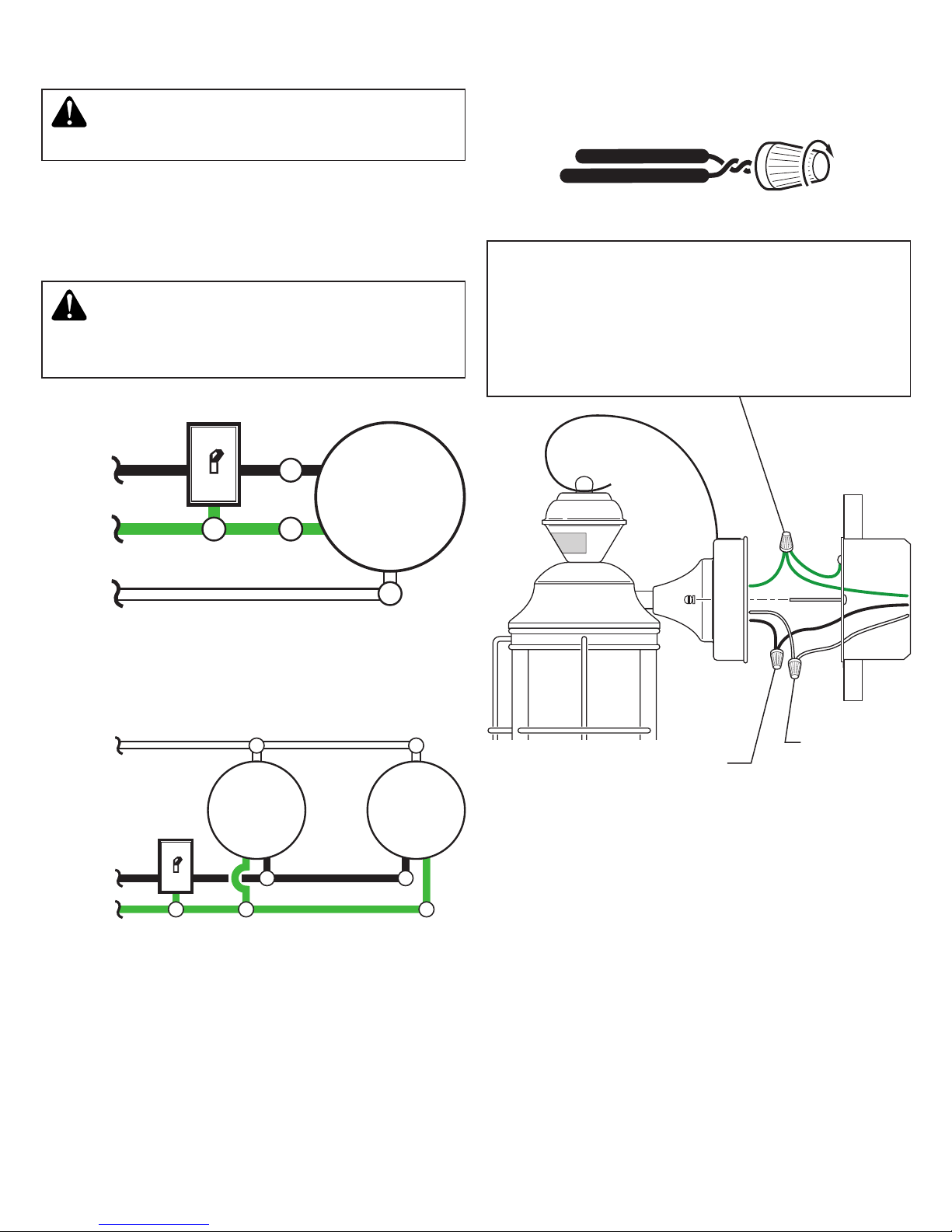
Black to black
White to white
Recommended Grounding Method
Use a green ground “pigtail” (not provided) and twist
one end together with the bare xture wire and the box
ground wire. Secure with a wire connector. Secure the
other end of the “pigtail” with the GND screw on the
mounting plate.
WIRING THE LIGHT FIXTURE
CAUTION: DO NOT connect the RED wire
unless you want to control other lights from the
motion sensor (see Optional Wiring).
Note: All wiring must be run in accordance with the National Electrical Code through conduit or another acceptable means. Contact a qualied electrician if there is any
question as to the suitability of the system.
WARNING: Turn power o at circuit breaker
or fuse.
Connect the xture wires to the wires in the junction box.
Twist the wires together and secure with wire connectors.
If you have a metal junction box, you may not need the green
“pigtail”. If you are unsure about the grounding method,
consult your local building code.
One Motion Light
Two Motion Lights
Black
White
Green
or Bare
Copper
Green
or Bare
Copper
Light
Fixture
Black
White
Light
Fixture
Light
Fixture
Page 5
5208949-01
Green
or Bare
Copper
Green
or Bare
Copper
Green
or Bare
Copper
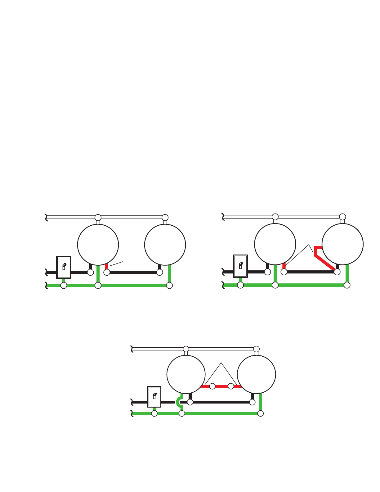
OPTIONAL WIRING
is xture is provided with a sensor rated for 360 Watts. Since the xture is only rated 100 Watts, 260 Watts of additional lighting may be controlled by this sensor.
When determining what a xture is rated for, do not simply look at the rating on the light bulb in the xture. Look at
the marking which species the maximum bulb wattage for which the xture is suitable.
Once you have selected the xtures to be connected and determined their maximum ratings, add these ratings up. For
instance, if you have 3 xtures rated 100 Watts, 150 Watts, and 75 Watts respectively, you have a total load of 325 Watts.
Wiring Diagram 1 – When wiring to control a standard light xture: Strip the motion sensor’s red wire and connect to
the standard light’s black wire. Connect all white wires together. Total xture ratings must not exceed 360 Watts (3.0 A).
Wiring Diagram 2 – When wiring to control another motion sensing light xture (Master / Slave): Strip the red wire in
both light xtures. Connect the red wire of the controlling (master) xture to the red and black wires of the controlled
(slave) xture. Connect all white wires together. Total xture ratings must not exceed 360 Watts (3.0 A).
Wiring Diagram 3 – When wiring so either motion light turns on the both motion lights (Master / Master): Strip the
red wire in both light xtures. Connect the red wire of one xture to the red wire of the second xture. Note: In most
installations, an additional wire (same gauge as existing house wire) will have to be installed in the house to connect the
two xtures as master / master. Connect all white wires together and all black wires together. Total xture ratings must
not exceed 360 Watts (3.0 A).
Black
White
Light
Fixture
Light
Fixture
(Standard)
Master
Slave
Black
White
Light
Fixture
Light
Fixture
Red
Red
Wiring Diagram 1 Wiring Diagram 2
Wiring Diagram 3
Master Master
Black
White
Red
Light
Fixture
Light
Fixture
Page 6
6 208949-01
Junction
Box
MOUNTING THE LIGHT FIXTURE
1. Make sure wire connectors and wires are inside the
junction box.
2. Slide the xture assembly onto the mounting screws.
Tighten decorative nuts removed in step 1 of
Light
Fixture Installation
section securely against xture base.
Mounting Screw
Decorative Nut
3. Install one medium base light bulb (100 Watt maximum,
tungsten incandescent).
TESTING AND ADJUSTMENTS
Initial Setup
e TEST mode overrides the photocell (daylight shuto
feature) and allows the light xture to be tested day or night
when the ON-TIME switch is in the TEST position. e
light will stay on for 5 seconds after all motion has stopped.
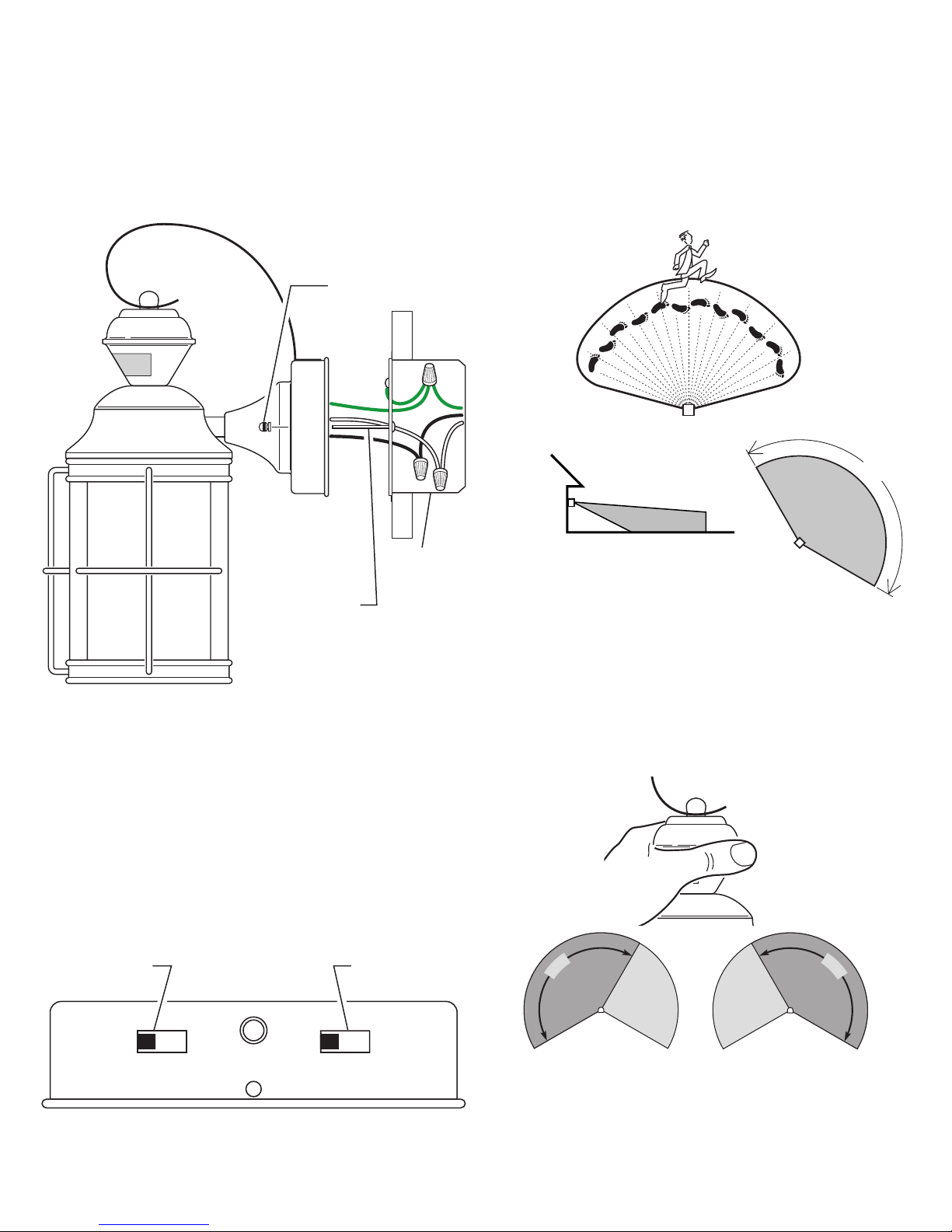
30 ft. (9.1 m)
6 ft. (1.8 m)
150°
Rotating Sensor Head to Change Coverage Area
1
5
0
°
1
5
0
°
6.
Move the sensor head left or right to change the coverage
area. Note: Grasp the sensor only as shown and turn
the entire sensor. Any other method may damage
the sensor. Do not force it past the stops.
1. Turn the DualBrite control to OFF.
2. Set the ON-TIME control to TEST.
3. Turn on the circuit breaker or fuse and the light switch.
4. Allow the sensor to completely warm up (90 seconds)
before beginning the setup process.
5. Perform a walk test. Walk in an arc across the front of
the sensor.
Sensor Controls
Maximum Range Maximum
Coverage Angle
(Top View)
TEST 1 5 10 MIN OFF 3 6 DUSK TO
HOUR DAWN
ON-TIME Switch DualBrite Switch
Page 7
7208949-01
Note: When rst turned on wait about 1 1/2 minutes for
the circuitry to calibrate.
* resets to Auto Mode at dawn.
Caulking Around Fixture Base
Mode: On-Time Works: Day Night
Test
5 Seconds x x
Auto
1, 5, or 10 Minutes x
Accent
3, 6 Hour, To Dawn x
Manual
To Dawn* x
Final Setup
1.
Adjust the sensitivity (SENS) to increase or decrease
the range as needed. Too much sensitivity may cause
false triggering due to heat sources in the coverage area
(see
Testing and Adjustments or Troubleshooting
section).
2. Set the amount of ON-TIME you want the light to
stay on after motion is detected (1, 5, or 10 minutes).
3. Set the DB® switch to o, 3 hours, 6 hours,
or dusk-to-dawn.
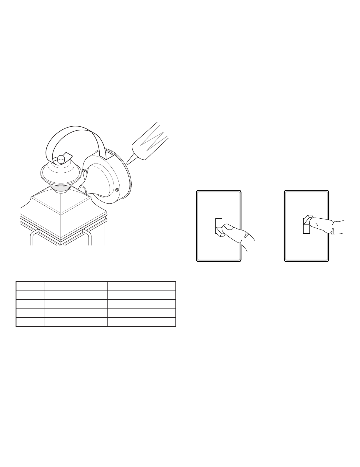
4. Caulk around xture base with silicone weather seal-
ant after all Testing and Adjustments are complete.
Turn Switch OFF for
1 to 2 seconds
Turn Switch
Back ON
CARE AND MAINTENANCE
• To prolong the original appearance, clean with clear water
and a soft damp cloth only.
• Do not use paints, solvents, or other chemicals on this
light xture. ey could cause a premature deterioration
of the nish. is is not a defect in the nish and will not
be covered by the warranty.
• Do not spray with hose or power washer.
• Optional DualBrite® Control – is optional feature
allows the light xture to turn on at a lower light level
after dusk (sunset) for the amount of time selected. When
motion is detected, the lights will turn on full bright. is
feature can be turned OFF and the motion sensor will
continue to work in AUTO mode.
• Manual Mode – is light can be activated to stay on full
bright after dusk (sunset) for only one night at a time. It
automatically resets to motion sensing at dawn (sunrise).
Manual mode must be re-activated each night. Note: If
power to the light xture is o for more than 5 seconds,
allow the electronic circuitry in the sensor to calibrate
(90 seconds) prior to switching to manual mode.
1. To turn on MANUAL mode, switch the light o at
the wall switch for 1 to 2 seconds and then back on.
2. To return to AUTO mode, switch the light o at the
wall switch for 1 to 2 seconds and then back on.
Note: e sensor will also reset to AUTO mode at
sunrise.
Operating Modes
• Motion Sensor (AUTO) – is light xture is designed
to automatically turn on when the sensor detects a temperature dierence moving across the front of the motion
sensor. e light will turn o automatically after a set
amount of time. e ON-TIME control should be set
to 1, 5, or 10 minute setting and the wall switch should
be left in the ON position at all times.
Page 8

8 208949-01
SPECIFICATIONS
Range ................................................................Up to 30 ft. (9.1 m) [varies with surrounding temperature]
Sensing Angle....................................................Up to 150°
Sensor Aiming Adjustment Angle ....................90°
Electrical Load .................................................. Up to 100 Watt Maximum Incandescent
Bulb Type ..........................................................Medium Base, Type “A”, 100 Watt Maximum
Sensor Capacity ................................................. Up to 360 Watt (3.0 A) Maximum Tungsten
Power Requirements ..........................................120 VAC, 60 Hz
Operating Modes ..............................................TEST, AUTO, and MANUAL MODE
ON-Timer ......................................................... 1, 5, 10 minutes
DB® Timer .......................................... O, 3, 6 hours, dusk-to dawn
Test Timer ......................................................... 5 Seconds
Manual Mode Timer .........................................Dusk-to-Dawn
SYMPTOM POSSIBLE CAUSE SOLUTION
Lights will not
come on.
1. Light switch is turned o.
2. Light bulb is loose or burned out.
3. Fuse is blown or circuit breaker is turned o.
4. Daylight turn-o is in eect.
5. Sensor not detecting movement.
6. Incorrect circuit wiring, if this is a new installation.
1. Turn light switch on.
2. Check bulb and replace if burned out.
3. Replace fuse or turn circuit breaker on.
4. Recheck after dark.
5. Re-aim the sensor to cover desired area.
6. Verify wiring is correct.
Lights come on in
daylight.
1. Light control may be installed in a relatively dark location.
2. Light control is in TEST.
1. e xture is operating normally under these conditions.
2. Set control switch to 1, 5, or 10 minutes.
Lights come on for
no apparent reason.
1. Light control may be sensing small animals or automobile
trac.
2. Sensitivity is set too high.
1. Re-aim sensor. Reduce sensitivity.
2. Reduce sensitivity.
Lights stay on
continuously.
1. e sensor may be picking up a heat source like an air vent,
dryer vent, or brightly painted, heat-reective surface.
2. Light control is in Manual Mode.
3. Light control is in DB® mode.
4. Sensitivity is set too high.
1. Re-aim sensor. Reduce sensitivity.
2. Switch to Auto.
3. Slide DB® switch to OFF position.
4. Reduce sensitivity.
Lights ash on
and o.
1. Light control is in the TEST mode and warming up.
2. Heat being reected from other objects may be aecting the
sensor.
1. Flashing is normal under these conditions.
2. Re-aim sensor. Reduce sensitivity.
Seasonal Temperature Changes – e closer the surrounding temperature is to a person’s body heat, the less sensitive the sensor will appear. e greater
the temperature dierence, the more sensitive the sensor will appear. e SENS control might need to be readjusted toward MIN or MAX as the outside
temperature changes for the dierent seasons. is is a normal part of the light sensor’s operation.
TROUBLESHOOTING GUIDE
Page 9

9208949-01
TECHNICAL SERVICE
Please call 1-800-858-8501 (English speaking only) for assistance
before returning product to store.
If you experience a problem, follow this guide. You may also want to visit our Web site at: www.hzsupport.com. If the
problem persists, call* for assistance at 1-800-858-8501 (English speaking only), 8:00 AM to 5:00 PM CST (M-F).
You may also write* to:
HeathCo LLC
P.O. Box 90045
Bowling Green, KY 42102-9045
ATTN: Technical Service
* If contacting Technical Service, please have the following information available: Model Number, Date of Purchase,
and Place of Purchase.
No Service Parts Available for this Product
Please keep your dated sales receipt, it is required for all warranty requests.
TWO YEAR LIMITED WARRANTY
is is a “Limited Warranty” which gives you specic legal rights. You may also have other rights which vary from state to state
or province to province.
For a period of two years from the date of purchase, any malfunction caused by factory defective parts or workmanship will be
corrected at no charge to you.
Not Covered - Repair service, adjustment and calibration due to misuse, abuse or negligence, light bulbs, batteries, and other
expendable items are not covered by this warranty. Unauthorized service or modication of the product or of any furnished component will void this warranty in its entirety. is warranty does not include reimbursement for inconvenience, installation, setup
time, loss of use, unauthorized service, or return shipping charges.
Finish Warranty Exclusions - Finishes for xtures installed outdoors are subject to change due to prolonged exposure to sunlight,
pollutants, and other environmental conditions. Metal nishes will naturally mature over time, changing in appearance and creating
a living nish. Painted nishes on outdoor xtures may naturally fade over time, depending on the xture’s exposure to the outdoor
elements. us, any claim for fading, discoloration, or “patina” of a nish on an outdoor xture is not applicable to the above warranty. See “Care and Maintenance”, page 7, for proper cleaning of the xture.
is warranty covers only HeathCo LLC assembled products and is not extended to other equipment and components that a customer
uses in conjunction with our products.
THIS WARRANTY IS EXPRESSLY IN LIEU OF ALL OTHER WARRANTIES, EXPRESS OR IMPLIED, INCLUDING
ANY WARRANTY, REPRESENTATION OR CONDITION OF MERCHANT ABILITY OR THAT THE PRODUCTS
ARE FIT FOR ANY PARTICULAR PURPOSE OR USE, AND SPECIFICALLY IN LIEU OF ALL SPECIAL, INDIRECT,
INCIDENTAL, OR CONSEQUENTIAL DAMAGES.
REPAIR OR REPLACEMENT SHALL BE THE SOLE REMEDY OF THE CUSTOMER AND THERE SHALL
BE NO LIABILITY ON THE PART OF HEATHCO LLC FOR ANY SPECIAL, INDIRECT, INCIDENTAL, OR
CONSEQUENTIAL DAMAGES, INCLUDING BUT NOT LIMITED TO ANY LOSS OF BUSINESS OR PROFITS,
WHETHER OR NOT FORESEEABLE. Some states or provinces do not allow the exclusion or limitation of incidental or
consequential damages, so the above limitation or exclusion may not apply to you.
Please keep your dated sales receipt, it is required for all warranty requests.
HeathCo LLC reserves the right to discontinue products and to change specications at any time without incurring any
obligation to incorporate new features in products previously sold.
Page 10

10 208949-01
INSTRUCCIONES PARA SU INSTALACIÓN
Y FUNCIONAMIENTO
INFORMACIÓN SOBRE LA SEGURIDAD ..................... 11
PREPARACIÓN ............................................. 11
FERRETERÍA OFRECIDA .................................... 11
INSTALACIÓN DEL APARATO DE LUZ .......................12
CABLEADO DEL APARATO DE LUZ .........................13
CONEXIÓN ALTERNA ......................................14
MONTAJE DEL APARATO DE LUZ ........................... 15
PRUEBAS Y AJUSTES ....................................... 15
CUIDADO Y MANTENIMIENTO ............................. 16
GUÍA DE INVESTIGACIÓN DE AVERÍAS .....................17
ESPECIFICACIONES ........................................17
SERVICIO TÉCNICO ........................................18
GARANTÍA LIMITADA A 2 AÑOS ............................ 18
Luz decorativa detectora de movimiento
* Bulb Saver - La luz se enciende tenue y aumenta gradualmente a su brillo completo. Cuando se apaga, la luz irá gradualmente de tenue a medio-brillante, hará una pausa, y luego
continuará atenuándose hasta que la luz se apague.
Para una descripción de la tecnología DualBrite ®, vea la página 16.
¿Preguntas?
Por favor, consulte la guía de solución de
problemas en este manual o llame a nuestro departamento de servicio técnico (solo para Inglés) al
1-800-858-8501, de 8:00 am - 5:00 pm, hora central,
de lunes a viernes antes de volverlo a la tienda.
Guarde este manual para referencia en el futuro.
ADJUNTE SU RECIBO AQUÍ
Se requiere recibo para todas las solicitudes de
garantía.
Fecha de compra
© 2016 HeathCo LLC 208949-01 S
Luz decorativa detectora de
movimiento DualBrite®
Modelo
4144
Page 11

11208949-01
INFORMACIÓN SOBRE LA
SEGURIDAD
Por favor lea y comprenda todo el manual antes de intentar
ensamblar, operar o instalar el producto.
Esta lámpara requiere de 120 voltios CA. Todo el cableado
debe ser de acuerdo con el Código Nacional de Electricidad
(Código Eléctrico Canadiense en Canadá). Algunos códigos
eléctricos locales requieren que la instalación sea hecha por
un electricista calicado.
ADVERTENCIA
• Desconecte la alimentación en el disyuntor o
fusible cuando haga el cableado de la lámpara
o cambie las bombillas. Ponga cinta adhesiva
sobre el interruptor del disyuntor y verique que
la electricidad esté apagada en la lámpara.
PRECAUCIÓN
• No corte ningún cable que tenga conectores
de cables instalados en fábrica ni retire los
conectores.
PREPARACIÓN
Antes de comenzar la instalación, asegúrese de que tiene
todas las piezas. Compare las piezas con la lista de ferretería
ofrecida. Si alguna pieza falta o está dañada, no intente
ensamblar, instalar o utilizar el producto.
Herramientas necesarias para el montaje (no incluidas):
Destornilladores Phillips y de cabeza plana, pinzas, separadores / cortadoras de alambre, multímetro, cinta aislante,
sellador de silicona, gafas de seguridad, guantes de trabajo
y escalera.
• Para una instalación fácil y para operar la luz utilizando
la modalidad Manual, cambie el aparato de luz existente
que funciona con un interruptor de pared.
• No lo conecte a atenuadores o temporizadores.
• Para un mejor funcionamiento, monte la unidad cerca de
6 pies (1,8 m) por encima del suelo.
Tiempo estimado de instalación: 30 minutos
3x – Conectores de alambre
2x – Tornillo del
soporte de montaje
FERRETERÍA OFRECIDA
Nota: Las ilustraciones pueden ser diferentes de la unidad
comprada.
A - (1x) Soporte de montaje
B - (2x) Tornillos de montaje
del aparato
C - (2x) Tuerca decorativa
(Este conjunto está sujeto a
la parte trasera del farol)
A
B
C
Page 12

12 208949-01
Paso del alambre
Paso del alambre
Como se enviaron Placa volteada
y girada
Paso del alambre
Placa de
montaje
Tuerca decorativa
Tornillo de
montaje
Tornillo de
montaje del
soporte
Placa de montaje
La caja de
empalme
INSTALACIÓN DEL APARATO DE LUZ
Para un mejor funcionamiento, instale el aparato a casi
1.8 m del suelo.
1. Quite dos tuercas decorativas.
2. Quite la placa de montaje.
3. Ajuste lo más que pueda los tornillos para montaje con
sus dedos.
4. Fije el control de sensibilidad en la parte posterior
del aparato a la posición MIN.
5. Atornille la placa de montaje a la caja de empalme.
Nota: Recomendamos tener un asistente que ayude a sostener el conjunto del farol durante el proceso de cableado.
Este aparato viene con un soporte de montaje universal.
Está pre-ensamblado en el aparato para acomodarse a la
mayoría de las aplicaciones de cajas de empalme.
Sin embargo, si las ranuras de la placa de montaje no se
alinean con los agujeros del tornillo de la caja de empalme:
1. Quite de la placa de montaje los tornillos de montaje
del aparato. Nota: No quite el tornillo de a tierra.
2. Fije el cable “exible” al tornillo de a tierra de la placa
de montaje (Vea
Método recomendado de conexión a tierra
para más información).
3. Voltee la placa de montaje
4. Voltee la placa de montaje de modo que el agujero de
paso del alambre esté en la parte derecha superior. Nota:
El agujero de paso del alambre en la placa de montaje
debe estar ubicado como se muestra abajo para que los
alambres de la parte de atrás del aparato puedan pasar.
5. Reinstale los tornillos de montaje del aparato y je la
placa de montaje a la caja de empalme como se muestra.
Tornillos del tierra
Tornillos del aparato
Tornillos del tierra
MAX
SENS
MIN
Page 13

13208949-01
ADVERTENCIA: Desconecte la alimentación en
el disyuntor o en el fusible.
Negro a negro
Método recomendado de conexión a tierra
Use un “cable exible” verde de tierra (no provisto) y
tuerza un extremo con el cable desnudo del aparato y con
el cable de a tierra de la caja. Asegúrelos con un conector
de cables. Asegure el otro extremo del “cable exible” con
el tornillo de a tierra de la placa de montaje.
CUIDADO: NO conecte el cable ROJO excepto
que desee controlar otras luces desde el detector de
movimiento (Vea Conexión Alterna).
Nota: Todo el cableado debe realizarse de acuerdo con el
Código Eléctrico Nacional usando tubería o algún otro
medio aceptable. Póngase en contacto con un electricista
calicado si tiene alguna pregunta referente a la aptitud
del sistema.
Conecte los alambres del aparato a los alambres de la caja
de empalme. Tuerza juntos los alambres y asegúrelos con
conectores de alambre.
Si tiene una caja de empalme de metal, no necesita el “cable
exible”. Si no está seguro del método de conexión a tierra,
consulte con el código local de construcción.
Luz de un movimiento
Luz de dos movimientos
Negro
Negro
Blanco
Blanco
Verde o
desnudo
Verde o
desnudo
Artefacto
de luz
Artefacto
de luz
Artefacto
de luz
Blanco a blanco
CABLEADO DEL APARATO DE LUZ
Page 14

14 208949-01
(Estándar)
Maestra Esclava
Rojo
Rojo
Esquema eléctrico 1 Esquema eléctrico 2
Esquema eléctrico 3
Maestra Maestra
Rojo
CONEXIÓN ALTERNA
Este aparato viene con un detector con una potencia de 360 Vatios. Puesto que este aparato tiene sólo una potencia de
100 vatios, 260 vatios de luz adicional pueden ser controlados por este detector.
Cuando desee determinar la clasicación de un aparato no vea tan sólo la potencia de la lámpara. Mire la indicación que
especique el voltaje máximo de la lámpara que el aparato puede aceptar.
Una vez que ha escogido los aparatos que se conectarán y ha determinado sus máximas potencias, súmelas. Por ejemplo,
si tiene 3 aparatos de 100 , 150 y 75 Vatios respectivamente, usted tendrá un total de 325 Vatios.
Esquema eléctrico 1 – Cuando prepare una conexión para controlar un aparato de luz estándar: Pele el alambre rojo
del detector de movimiento y conéctelo al alambre negro de la luz estándar. Conecte todos los alambres blancos. La
capacidad total no debe exceder los 360 Vatios (3.0 A).
Esquema eléctrico 2 – Cuando prepare una conexión para controlar otro aparato de luz detector de movimiento:
Pele el alambre rojo en ambos aparatos de luz. Conecte el alambre rojo del aparato controlador (maestro) a los alambres
rojo y negro del aparato controlado (esclavo). Conecte todos los alambres blancos. La capacidad total no debe exceder
los 360 Vatios (3.0 A).
Esquema eléctrico 3 – Cuando haga el cableado para que cualquier luz de movimiento prenda las dos luces que detectan movimiento (Maestro / Maestro): Pele el conductor rojo de ambos aparatos de luz. Conecte el conductor rojo
de un aparato al conductor rojo del otro aparato. Nota: en la mayoría de las instalaciones se deberá instalar un conductor
adicional (del mismo calibre que el conductor de la casa) dentro de la casa para conectar los dos aparatos como maestro /
maestro. Conecte entre si todos los alambres blancos y todos los alambres negros. La potencia nominal total del aparato
no debe ser más de 360 vatios (3.0 Amp).
Negro
Negro
Negro
Blanco
Blanco
Blanco
Verde o
desnudo
Verde o
desnudo
Verde o
desnudo
Artefacto
de luz
Artefacto
de luz
Artefacto
de luz
Artefacto
de luz
Artefacto
de luz
Artefacto
de luz
Page 15

15208949-01
MONTAJE DEL APARATO DE LUZ
1. Asegúrese que los conectores de alambre y los alambres
estén dentro de la caja de empalme.
2. Deslice el conjunto del aparato sobre los tornillos de
montaje. Apriete las tuercas decorativas quitadas en
el paso 1 de la sección
Instalación del Aparato de Luz
rmemente en la base del aparato.
3. Instale una base media para bombilla (100 vatios máximo,
tungsteno incandescente).
PRUEBAS Y AJUSTES
Conguración inicial
La modalidad TEST anula la fotocélula (función de apagado
durante el día) y permite que el aparato de luz sea probado
durante el día o la noche cuando el interruptor ON-TIME
se encuentra en la posición TEST. La luz permanecerá
encendida por 5 segundos después de que todo movimiento
se haya detenido.
6.
Mueva la cabeza del detector hacia la izquierda o derecha
para cambiar el área de protección. Nota: Agarre sólo
el detector, como se muestra, y gire todo el detector.
Cualquier otro método puede dañarlo. No lo forcé
más allá de los puntos de parada.
1. Gire el control DualBrite a OFF.
2. Fije el control ON-TIME a TEST.
3.
Encienda el disyuntor o fusible y el interruptor de la luz.
4. Deje que el sensor se caliente por completo (90 segundos)
antes de comenzar el proceso de instalación.
5. Haga una prueba de paso. Camine en arco por la parte
delantera del detector.
Tuerca decorativa
La caja de
empalme
Tornillo de
montaje
Controles del detector
Giro de la cabeza del detector para cambiar el área de cobertura
1
5
0
°
1
5
0
°
30 ft. (9.1 m)
6 ft.
(1.8 m)
150°
Alcance Máximo
Ángulo de
Cobertura Máxima
(
Vista desde arriba
)
TEST 1 5 10 MIN OFF 3 6 DUSK TO
HOUR DAWN
Interruptor de duración
(ON-TIME)
Interruptor DUALBRITE
Page 16

16 208949-01
Nota: Cuando encienda por primera vez, espere 1 1/2 minutos
para que los circuitos se calibren.
*Se pone en Automático al amanecer.
Modalidad: A tiempo: Trabaja:
Día Noche
Prueba
5 segundos x x
Automático
1, 5 o 10 min. x
Adorno
3, 6 hrs, hasta el
amanecer
x
Manual
Hasta el amanecer* x
Calafateo alrededor de la base del aparato
Modalidades de operación
Apague el interruptor
de 1 a 2 segundos
Vuelva a prender
el interruptor
CUIDADO Y MANTENIMIENTO
• Para prolongar la apariencia original, limpie solo con agua
clara y un paño suave y húmedo.
• No utilice pinturas, disolventes u otros productos químicos
en esta lámpara. Pueden causar un deterioro prematuro
del acabado. Esto no es un defecto en el acabado y no
estará cubierto por la garantía.
• No lo rocíe con una manguera o una lavadora a presión.
Conguración nal
1. Regule la sensibilidad (SENS) para aumentar o disminuir el alcance según lo que necesite. Demasiada
sensibilidad puede ocasionar falsas alarmas debido a
fuentes de calor en la zona de cobertura (vea la sección
Ajuste de la zona de cobertura
o la sección
Análisis de averías
).
2. Fije el período de tiempo (ON-TIME) que la luz debe
quedarse prendida después de detectar movimiento (1,
5 o 10 minutos).
3. Ponga el interruptor DBMD en apagado (o),
3 horas, 6 horas, o dusk-to-dawn (del anochecer al
amanecer).
4. Calafatee alrededor de la base del aparato con un
sellador de silicona contra la intemperie después de
completar todos los Pruebas y Ajustes.
El control ON-TIME se debe jar a 1, 5 o 10 minutos
y al interruptor de pared se lo debe dejar siempre en la
posición ON.
• Control opcional DualBrite® – Esta función opcional
permite que la lámpara se encienda a un nivel de luz baja
después del atardecer (puesta del sol) por la cantidad de
tiempo seleccionada. Cuando se detecta movimiento, las
luces se prenderán con todo su resplandor. Esta característica puede desactivarse y el detector de movimiento
seguirá trabajando en la modalidad AUTO.
• Modalidad Manual – Esta luz se puede activar para que
permanezca con todo su resplandor después del atardecer
(puesta del sol) por sólo una noche por vez. Se restablece
automáticamente para detectar movimiento al amanecer
(salida del sol). La modalidad manual se debe reactivar
cada noche. Nota: Si la lámpara está apagada por más de
5 segundos, deje que el circuito electrónico del detector
se calibre (90 segundos) antes de cambiar a la modalidad
manual.
1. Para activar la modalidad MANUAL, apague la luz
en el interruptor de pared de 1 a 2 segundos y vuelva a
prenderla.
2. Para volver a la modalidad AUTO, apague la luz en
el interruptor de pared de 1 a 2 segundos y vuelva a
prenderla. Nota: El detector también se restablecerá a
la modalidad AUTO al amanecer.
• Detector de movimiento (AUTO) – Esta lámpara está
diseñada para prenderse automáticamente cuando el sensor
detecta una diferencia de temperatura que se mueve por
el frente del detector de movimiento. La luz se apagará
automáticamente después de un determinado tiempo.
Page 17

17208949-01
ESPECIFICACIONES
Alcance ..................................................................
Hasta 9.1 m. (varía con la temperatura del medio ambiente).
Ángulo de detección .............................................. Hasta 150°
Ajuste del ángulo de visión del sensor ................... 90°
Carga Eléctrica ...................................................... Hasta un máximo de 100 vatios de incandescente
Tipo de bombilla ................................................... Casquillo mediano, tipo “A” de 100 vatios máximo
Capacidad del Detector .........................................
Foco de tungsteno de hasta 360 vatios (3.0 A) como máximo
Requisitos de Energía ............................................ 120 VCA, 60 Hz
Fases de Operación ................................................PRUEBA, AUTOMÁTICO y MODO MANUAL
Temporizador de duración
(del encendido) ...................................................... 1, 5 o 10 minutos
Temporizador de DB® ............................. Apagado, 3, 6 horas, del atardecer al amanecer
Temporizador de prueba ........................................ 5 segundos
Temporizador de la fase manual ............................ Del atardecer al amanecer
GUÍA DE INVESTIGACIÓN DE AVERÍAS
SÍNTOMA POSIBLE CAUSA SOLUCIÓN
Las luces no se prenden. 1. El interruptor de luz está apagado.
2. La bombilla está oja o quemada.
3. El fusible está quemado o el cortacircuitos está
apagado.
4. La modalidad de apagado durante el día está en
efecto.
5. El sensor no detecta el movimiento.
6. Alambrado incorrecto, si ésta es una nueva instalación.
1. Encienda el interruptor de luz.
2. Revise la lámpara y cámbiela si está quemada.
3. Cambie el fusible encienda el disyuntor.
4. Revíselo después del anochecer.
5. Apunte de nuevo el detector para cubrir las áreas deseadas.
6. Verique que el cableado esté correcto.
Las luces se prenden durante
el día.
1. El control de luz puede estar instalado en un lugar
relativamente obscuro.
2. El control de luz está en fase de Prueba.
1. El aparato está funcionando normalmente bajo estas condiciones.
2. Fije el interruptor de control a 1, 5 o 10 minutos.
Las luces se prenden sin
ninguna razón aparente.
1. El control de luz puede estar detectando animales
pequeños o el trásito de automóviles.
2. La Sensibilidad es demasiado alta.
1. Reposicione el detector. Reduzca la sensibilidad.
2. Reduzca la sensibilidad.
Las luces se quedan prendidas
continuamente.
1. El sensor puede detectar fuentes de calor, como
ductos de calefacción y de aire acondicionado, o
supercies resplandecientes que reejan la luz.
2. El control de luz está en fase Manual.
3.
El control de luz está en la modalidad DB®.
4. La Sensibilidad es demasiado alta.
1. Reposicione el detector. Reduzca la sensibilidad.
2. Cámbiela a Auto.
3. Deslice el interruptor DB® a la posición de apagado
(o).
4. Reduzca la sensibilidad.
La luce se prenden y se apagan. 1. El control de luz está en fase de Prueba y calen-
tándose.
2. El calor que se reeja de otros objetos pueden estar
afectando al detector.
1. El prenderse y apagarse es normal bajo estas condiciones.
2. Reposicione el detector. Reduzca la sensibilidad.
Cambios estacionales de temperatura - Cuanto más cerca esté la temperatura ambiental al calor del cuerpo de una persona, el detector parecerá menos
sensible. Cuanto mayor sea la diferencia de temperatura, el detector parecerá más sensible. El control SENS puede necesitar ser recalibrado hacia MIN o
MAX a medida que la temperatura exterior cambia debido a las diferentes estaciones del año. Esta es una parte normal del funcionamiento del detector de luz.
Page 18

18 208949-01
SERVICIO TÉCNICO
Favor de llamar al 1-800-858-8501 (sólo para hablar en inglés) para pedir ayuda antes de
devolver el producto a la tienda.
Si tiene algún problema, siga esta guía. Usted puede también visitar nuestro sitio Web: www.hzsupport.com. Si el
problema continúa, llame al 1-800-858-8501 (sólo para hablar en inglés), de 8:00 AM a 5:00 PM CST (L-V). Usted
puede también escribir a:
HeathCo LLC
P.O. Box 90045
Bowling Green, KY 42102-9045
ATTN: Technical Service (Servicio Técnico)
* Si se llama al Servicio Técnico, por favor tener lista la siguiente información: Número de Modelo, Fecha de compra y
Lugar de compra.
No hay piezas de servicio disponibles para este producto.
Por favor guarde su recibo de venta fechado; se lo requiere para cualquier solicitud de garantía.
GARANTÍA LIMITADA A 2 AÑOS
Esta es una “Garantía Limitada” que le da a Ud. derechos legales especícos. Usted puede también tener otros derechos que varían
de estado a estado o de provincia a provincia.
Por un período de 2 años desde la fecha de compra, cualquier mal funcionamiento ocasionado por partes defectuosas de fábrica o
mano de obra será corregido sin cargo para Ud.
No cubierto - Servicio de reparación, ajuste y calibración debido al mal uso, abuso o negligencia, bombillas, baterías, u otras partes
fungibles no están cubiertas por esta garantía. Los Servicios no autorizados o modicaciones del producto o de cualquier componente
que se provee invalidarán esta garantía en su totalidad. Esta garantía no incluye reembolso por inconveniencia, instalación, tiempo
de instalación, perdida de uso, servicio no autorizado, o costos de transporte de retorno.
Exclusiones de garantía de los acabados – Los acabados de los aparatos instalados al aire libre están sujetos a cambios debido a su
exposición prolongada a la luz solar, a los contaminantes y a otras condiciones ambientales. Los acabados de metal, naturalmente,
madurarán con el tiempo, cambiando su apariencia y creando un acabado patinado. Los acabados pintados en aparatos al aire libre
pueden desteñirse en forma natural con el tiempo, dependiendo de la exposición del aparato a la intemperie. Por lo tanto, cualquier
reclamo por desteñido, decoloración o "pátina" del acabado de un accesorio al aire libre no es aplicable a la garantía antes mencionada.
Vea la sección "Cuidado y mantenimiento" en la página 16, para una limpieza adecuada del aparato.
Esta garantía cubre solamente los productos ensamblados por HeathCo LLC y no se extiende a otros equipos o componentes que
el consumidor usa junto con nuestros productos.
ESTA GARANTÍA ESTÁ EXPRESAMENTE EN LUGAR DE OTRAS GARANTÍAS, EXPRESADAS O SOBREENTENDIDAS, INCLUYENDO CUALQUIER GARANTÍA, REPRESENTACIÓN O CONDICIÓN DE COMERCIABILIDAD O QUE LOS PRODUCTOS SE ADAPTEN PARA CUALQUIER PROPÓSITO O USO EN PARTICULAR,
Y ESPECIFICAMENTE EN LUGAR DE TODOS LOS DAÑOS ESPECIALES, INDIRECTOS, INCIDENTALES Y
CONSECUENTES.
LA REPARACIÓN O EL REEMPLAZO DEBERÍA SER LA ÚNICA SOLUCIÓN DEL CLIENTE Y NO HABRÁ
RESPONSABILIDAD POR PARTE DE HEATHCO LLC POR CUALQUIER DAÑO ESPECIAL, INDIRECTO, INCIDENTAL O CONSECUENTE, INCLUIDOS PERO NO LIMITADOS A CUALQUIER PÉRDIDA DE NEGOCIO
O GANACIAS SEAN O NO PREVISIBLES. Algunos estados o provincias no permiten la exclusión o limitación de daños
incidentales o consecuentes, de modo que la limitación o exclusión arriba indicada puede que no se aplique a Ud.
Por favor guarde su recibo de venta fechado; se lo requiere para cualquier solicitud de garantía.
HeathCo LLC se reserva el derecho de descontinuar productos y de cambiar especicaciones a cualquier momento sin
incurrir en ninguna obligación de tener que incorporar nuevas características en los productos vendidos con anterioridad.
Page 19

19208949-01
INSTRUCTIONS D’INSTALLATION ET
MODE D’EMPLOI
RENSEIGNEMENTS DE SÉCURITÉ ........................... 20
PRÉPARATION .............................................20
QUINCAILLERIE FOURNIE .................................. 20
INSTALLATION DU LUMINAIRE ............................. 21
BRANCHEMENT DU LUMINAIRE ............................22
CÂBLAGE FACULTATIF .....................................23
MONTAGE DU LUMINAIRE .................................24
ESSAIS ET RÉGLAGES ...................................... 24
ENTRETIEN ET MAINTENANCE ............................. 25
GUIDE DE DÉPANNAGE ....................................26
FICHE TECHNIQUE ......................................... 26
SERVICE TECHNIQUE ......................................27
GARANTIE LIMITÉE DE 2 ANS ..............................27
Luminaire décoratif à détecteur de mouvement
* ÉconoLampe - L’éclairage s’allume à faible intensité et passe
graduellement à la pleine intensité. Lorsque l’éclairage s’éteint,
l’intensité est graduellement réduite de moitié, fait une pause,
puis la réduction se poursuit jusqu’à l’extinction nale.
Pour une description de la technologie DualBriteMD, consultez
la page 25.
Des questions?
Consultez le guide de dépannage du guide ou
communiquez avec le service technique (en anglais
seulement) au 1800858-8501, de 8 h à 17 h, HNC,
du lundi au vendredi avant de retourner chez le
détaillant.
Conservez ce guide à titre de référence.
FIXEZ VOTRE REÇU DE CAISSE ICI
Le reçu est nécessaire pour toute demande sous
garantie.
Date d’achat
© 2016 HeathCo LLC 208949-01 S
Luminaire décoratif à
détecteur de mouvement et
fonction DualBrite
MD
Modèle
4144
Page 20

20 208949-01
RENSEIGNEMENTS DE SÉCURITÉ
Veuillez lire et bien comprendre le guide avant de tenter
d’assembler, d’utiliser ou d’installer le produit.
Ce luminaire exige une alimentation de 120 volts c.a. Tout
le câblage doit être conforme au National Electrical Code
(Code canadien de l’électricité au Canada). Certains codes
électriques locaux exigent qu’un électricien accrédité installe
ce luminaire.
AVERTISSEMENT
• Coupez l’alimentation au niveau du disjoncteur
ou du fusible pour brancher le luminaire ou
remplacer les lampes. Placez un bout de ruban
adhésif sur le disjoncteur assurez-vous que le
courant est bien coupé au luminaire.
ATTENTION
• Ne coupez aucun l doté de capuchons de
connexion installés en usine et ne retirez pas ces
capuchons de connexion.
PRÉPARATION
Avant de commencer l’installation du produit, assurez-vous
de bien avoir toutes les pièces. Comparez les pièces avec la
liste de la quincaillerie fournie. S’il manque une pièce ou
si l’une d’elles est endommagée, ne tentez pas d’assembler
d’installer ou d’utiliser le produit.
Outils nécessaires à l’assemblage (non fournis):Tournevis
Phillips et à lame droite, pinces, pinces à dénuder et à couper,
multimètre, ruban adhésif électrique, scellant d’étanchéité
à la silicone, lunettes de sécurité, gants de travail et échelle.
• Pour une installation et une utilisation faciles au moyen du
mode Manuel, remplacez un luminaire existant commandé
par interrupteur mural.
• Ne connectez pas ce luminaire à un gradateur ni à une
minuterie.
• Pour un meilleur rendement, installez le luminaire à
environ 6 pieds (1,8 m) du sol.
Durée estimative de l’installation:30 minutes
3x – Capuchons de
connexion
2x – Vis de montage
du support
A - (1x) Support de montage
B - (2x) Vis de montage du
luminaire
C - (2x) Écrou décoratif
(Cet élément est xé
à l’endos du couvercle de
la lanterne.)
QUINCAILLERIE FOURNIE
Remarque: Les illustrations peuvent être diérentes de
l’appareil acheté.
A
B
C
Page 21

21208949-01
Vis de
montage du
support
Remarque : Il est recommandé de demander à une autre
personne de tenir la lanterne pendant le passage des ls.
Ce luminaire vous est fourni avec un support universel; déjà
xé au luminaire, ce support convient à la majorité des boîtes
de raccordement électrique.
Toutefois, si les rainures de la plaque de montage ne correspondent pas aux trous des vis de la boîte :
1. Retirez les vis de xation au luminaire de la plaque de
montage. Remarque : Ne retirez pas la vis de mise à la
terre.
2. Fixez la « rallonge » du l de terre à la vise de mise à
la terre de la plaque de montage (consultez la section
Méthode de mise à la terre recommandée
pour plus de détails).
3. Retournez la plaque de montage.
4. Faites tourner la plaque de montage de sorte que l’orice
de passage des ls se trouve dans le coin supérieur droit.
Remarque : L’orice de passage des ls de la plaque de
montage doit être placé comme illustré ci-dessous pour
permettre le passage des ls à l’arrière du luminaire.
5. Remettez en place les vis de xation au luminaire et la
vis de mise à la terre, puis xez la plaque de montage à
la boîte de raccordement, comme illustré.
Tel qu’expédié Plaque retournée,
après rotation
Passage
des ls
Passage
des ls
Passage des ls
Vis de mise à la terre
Plaque de
montage
Écrou décoratif
Vis de montage
Plaque de montage
Boîte de
jonction
INSTALLATION DU LUMINAIRE
Pour un rendement optimal, montez le luminaire à environ
1,8 m au-dessus du sol.
1. Retirez les deux écrous décoratifs.
2. Enlever la plaque de montage.
3. Serrez à la main les vis de la croix.
4. Réglez à MIN la commande de sensibilité à l’arrière
du luminaire.
5. Fixer la plaque de montage à la boîte de jonction.
Vis de mise à la
terre
Vis de xation au
luminaire
MAX
SENS
MIN
Page 22

22 208949-01
AVERTISSEMENT: NE PAS raccorder le l ROUGE
à moins que vous ne vouliez commander d’autres
luminaires au moyen du détecteur de mouvement
(voir Câblage Facultatif).
Remarque : Le câblage doit être conforme aux exigences
du Code national de l’électricité et être installé dans des
canalisations ou autres dispositifs acceptables. Si vous
avez des doutes concernant la convenance du système,
consultez un électricien reconnu.
MISE EN GARDE : Coupez l’alimentation au
disjoncteur ou au fusible.
Branchez les ls du luminaire aux ls dans la boîte de
raccordement. Torsadez ces ls ensemble, puis ajoutez-y
un connecteur de ls.
Si la boîte de jonction est en métal, vous pourriez nécessiter
une «queue de cochon» verte. Si vous avez des doutes sur la
méthode de mise à la terre, consultez votre code du bâtiment.
Une lanterne à détecteur de mouvement
Deux lanternes à détecteur de mouvement
Noir
Blanc
Vert ou
dénudé
Luminaire
Luminaire Luminaire
Noir
Blanc
Vert ou
dénudé
noir/noir
blanc/blanc
Méthode de mise à la terre recommandée
Utilisez une «queue de cochon» verte (non fournie) et
torsadez-en une extrémité avec le l nu du luminaire et
le l de terre de la boîte de jonction. Utilisez un serre-ls.
Fixez l’autre extrémité de la «queue de cochon» avec la
vis de terre (GND) sur la plaque de montage.
BRANCHEMENT DU LUMINAIRE
Page 23

23208949-01
CÂBLAGE FACULTATIF
Ce luminaire est pourvu d’un capteur de 360 W. Comme ce luminaire ne consomme que 100 W, le capteur peut commander 260 W d’éclairage supplémentaire.
Lorsque vous déterminez l’intensité que peut supporter un luminaire, ne vous contentez pas de simplement lire l’intensité
indiquée sur l’ampoule. Recherchez l’étiquette indiquant le wattage d’ampoule maximal de l’appareil.
Une fois que vous avez choisi les luminaires à raccorder et déterminé leur intensité maximale respective, additionnez les
intensités. Par exemple, si vous avex 3 appareils dont l’intensité est 100 Watts, 150 Watts et 75 Watts respectivement,
la charge totale est 325 Watts.
Diagramme de câblage 1 – Câblage d’un luminaire standard : dénudez le l rouge du détecteur de mouvement
et raccordez-le au l noir du luminaire standard. Raccordez tous les ls blancs ensemble. L’intensité maximale ne noit
pas dépasser 360 Watts (3,0 A).
Diagramme de câblage 2 – Câblage d’un autre luminaire à détecteur de mouvement (Maître / Satellite) :
dénudez le l rouge des deux luminaires. Branchez le l rouge du luminaire de commande (maître) aux ls rouge et
noir du luminaire commandé (satellite). Branchez tous les ls blancs ensemble. La consommation totale des luminaires
ne doit pas être supérieure à 360 Watts (3,0 A).
Diagramme de câblage 3 – Câblage de sorte que l’une ou l’autre des commandes déclenche les deux luminaires (Maître / Maître) : dénudez le l rouge des deux luminaires. Branchez le l rouge d’un luminaire au l rouge du
second luminaire. Remarque : Dans la plupart des cas, un l supplémentaire (de même calibre que le l de la résidence)
doit être installé pour raccorder les deux luminaires en conguration « principal / principal ». Raccordez tous les ls
blancs ensemble, puis faites de même avec tous les ls noirs. La consommation totale des luminaires ne doit pas être
supérieure à 360 Watts (3,0 A).
Maître Satellite
Maître Maître
Diagramme de câblage 1
Noir
Noir
Noir
Blanc
Blanc
Blanc
Vert ou
dénudé
Vert ou
dénudé
Vert ou
dénudé
Diagramme de câblage 2
(Standard)
Luminaire LuminaireLuminaire Luminaire
Rouge
Rouge
Luminaire Luminaire
Rouge
Diagramme de câblage 3
Page 24

24 208949-01
Boîte de
jonction
MONTAGE DU LUMINAIRE
1. Assurez-vous que les capuchons de connexion et les ls
sont bien insérés dans la boîte de jonction.
2. Faites glisser le socle du luminaire sur les vis de montage.
Serrez solidement les écrous décoratifs retirés à l’étape
1 de la section
Installation du luminaire
contre la base
du luminaire base.
Vis de montage
Écrou décoratif
3. Installez une ampoule à culot moyen (maximum de
100 W, tungstène à incandescence).
ESSAIS ET RÉGLAGES
Réglage initial
Le mode TEST contourne la photocellule (fonction d’arrêt
pendant la journée) et permet de faire l’essai du luminaire
pendant la journée ou la nuit lorsque le commutateur «ONTIME» est en position TEST. L’éclairage demeure allumé
pendant cinq secondes après que le mouvement s’est arrêté.
6. Déplacer la tête du détecteur vers la gauche, le droit ou
le côté pour modier la zone de couverture. Remarque:
Saisir le détecteur seulement de la façon indiquée et
tourner tout l’ensemble. Toute autre façon de faire
pourrait endommager le détecteur. Ne pas le forcer
au-delà des butées.
1. Placez la commande DualBrite à OFF.
2. Placez la commande ON-TIME à TEST.
3. Réenclenchez le disjoncteur ou le fusible et placez
l’interrupteur à ON.
4. Laissez le détecteur se réchauer complètement (90
secondes) avant de commencer le réglage.
5. Eectuez un test de passage. Déplacez-vous selon un
arc de cercle devant le détecteur.
30 ft. (9.1 m)
6 ft.
(1.8 m)
150°
Commandes du détecteur
Portée maximale Angle de
couverture maximale
(Vue en plongée)
Rotation du capteur pour modier la zone de couverture
1
5
0
°
1
5
0
°
TEST 1 5 10 MIN OFF 3 6 DUSK TO
HOUR DAWN
Commutateur de DURÉE
DE FONCTIONNEMENT
Commutateur DualBrite
Page 25

25208949-01
* Revient au mode automatique au lever du soleil.
Remarque : Après mise en circuit, attendre enron 1 1/2
minute pour que l’étalonnage du circuit soit complété.
Mode: Temps en circuit:
En fonction:
jour nuit
Essai
5 secondes x x
Auto
1, 5 ou 10 min. x
Accentuation
3, 6 h jusqu’à l’aurore x
Manuel
au choix, amanecer* x
Réglage nal
1. Régler la sensibilité (SENS) selon les besoins. Une trop
grande sensibilité pourrait entraîner des déclenchements
intempestifs attribuables à des sources de chaleur dans
la zone de couverture (consultez les sections
Essais et
réglages
ou
Guide de dépannage
).
2. Réglez la période (ON-TIME) pendant laquelle vous
souhaitez que l’éclairage fonctionne après détection
d’un mouvement (1, 5 ou 10 minutes).
3. Placer le commutateur DBMD à fermé (o), 3
heures, 6 heures ou crépuscule-aurore (dusk-to-dawn).
4. Appliquer un scellant à la silicone tout autour de la
base du luminaire, une fois tous les Essais et Réglages
terminés.
ENTRETIEN ET MAINTENANCE
• Pour conserver l’apparence originale du luminaire, nettoyez-le uniquement au moyen d’eau douce et d’un chion
mouillé.
• N’appliquez aucune peinture, solvant ou produit chimique
sur ce luminaire. Cela pourrait entraîner une détérioration
prématurée du ni. Il ne s’agit pas d’un défaut du ni et
ce ne sera pas couvert dans le cadre de la garantie.
• Évitez d’asperger au moyen d’un boyau ou d’un nettoyeur
à pression.
Modes de fonctionnement
Scellant d’étanchéité autour de la base
Placez l’interrupteur à
OFF pendant
1 à 2 secondes.
Replacez l’interrupteur
à ON.
La commande ON-TIME devrait être réglée à 1, 5 ou 10
minutes et l’interrupteur devrait être constamment placé
en position ON.
• Commande DualBriteMD facultative – Cette fonction
facultative fait en sorte que le luminaire s’allume à
intensité réduite après le coucher du soleil, pendant le
délai de fonctionnement xé. Lorsqu’un mouvement est
détecté, la lumière s’allume à pleine intensité. Cette
fonction peut être désactivée (OFF), et le détecteur de
mouvement continuera de fonctionner en mode AUTO.
• Mode Manuel – Ce luminaire peut être réglé pour
demeurer allumé à pleine intensité après le coucher du
soleil, une nuit à la fois. Il revient automatiquement à l’état
initial (AUTO) au lever du soleil. Le mode Manuel doit
être réactivé chaque soir. Remarque :En cas de coupure
de courant pendant plus de 5 secondes, il faut laisser au
circuit électronique le temps de s’étalonner (90 secondes)
avant de passer en mode manuel.
1. Pour activer le mode MANUEL, fermez le luminaire au
niveau de l’interrupteur mural pendant 1 à 2 secondes,
puis remettez-le sous tension.
2. Pour repasser en mode AUTO, fermez le luminaire au
niveau de l’interrupteur mural pendant 1 à 2 secondes,
puis remettez-le sous tension. Remarque:Le détecteur
repassera aussi en mode AUTO au lever du soleil.
•
Détecteur de mouvement (AUTO) – Ce luminaire est
conçu pour s’allumer automatiquement lorsque le détecteur décèle une diérence de température qui se déplace
devant lui dans la zone de couverture. La lumière s’éteindra
automatiquement après le délai de fonctionnement xé.
Page 26

26 208949-01
FICHE TECHNIQUE
Portée ...........................................................................Jusqu’à 9,1 m [varie selon la température environnante]
Angle de détection ........................................................
Jusqu’à
150°
Angle d’ajustement de visée du capteur ........................ 90°
Charge électrique .......................................................... Jusqu’à une ampoule incandescentes, pour un maximum
de 100 Watt
Type d’ampoule ............................................................ Culot moyen, type A, 100 W maximum
Capacité du détecteur ................................................... Tungstène jusqu’à 360 watts (3,0 A) maximum
Courant requis .............................................................. 120 V c.a., 60 Hz
Modes de fonctionnement ............................................ ESSAI, AUTO et MANUEL
Minuterie de fonctionnement ....................................... 1, 5 ou 10 minutes
Minuterie de DBMD ........................................ Fermé, 3, 6 heures, crépuscule-aurore
Minuterie d’essai ........................................................... 5 secondes
Minuterie du mode MANUEL....................................
Du coucher au lever du soleil
SYMPTÔME CAUSE POSSIBLE SOLUTION
L’éclairage ne s’allume
pas.
1. L’interrupteur d’éclairage est hors tension.
2. L’ampoule est lâche ou grillée.
3. L e fusible a sauté ou le disjoncteur a été déclenché.
4. La fonction de fermeture pendant le jour est activée.
5. Capteur, sans détection de mouvement.
6. Mauvais câblage du circuit, dans le cas d’une
nouvelle installation.
1. Mettre l’interrupteur sous tension.
2. Vérier l’ampoule et la remplacer si elle est grillée.
3. Remplacer le fusible ou ré-enclencher le disjoncteur.
4. Essayer de nouveau après la tombée de la nuit.
5. Réorienter le détecteur pour obtenir la couverture désirée.
6. S’assurer que le câblage est approprié.
L’éclairage s’allume en
plein jour.
1. La commande peut être installée dans un endroit
relativement sombre.
2. La commande d’éclairage est en mode essai.
1. Le luminaire fonctionne normalement dans de telles conditions.
2. Réglez le commutateur de commande à 1, 5 ou 10 minutes.
L’éclairage s’allume
sans raison apparente.
1. Le capteur détecte peut-être de petits animaux ou
la circulation automobile.
2. Le réglage de portée est trop élevé.
1. Réorientez le détecteur. Réduisez la portée.
2. Réduisez la portée.
L’éclairage
demeure allumé
continuellement.
1. Le capteur peut percevoir une source de chaleur
comme une sortie d’air, un évent de sécheuse ou
une surface de couleur claire rééchissant la chaleur.
2. La commande d’éclairage est en mode Manuel.
3. La commande d’éclairage est en mode
DBMD.
4. Le réglage de portée est trop élevé.
1. Réorientez le détecteur. Réduisez la portée.
2. Faites-la passer au mode Auto.
3. Faire glisser le commutateur DBMD en position OFF.
4. Réduisez la portée.
L’éclairage clignote. 1. La commande d’éclairage est en mode essai et se
réchaue.
2. L a chaleur qui est rééchie par d’autres objets peut
aecter la commande d’éclairage.
1. Le clignotement est normal dans ces deux cas.
2. Réorientez le détecteur. Réduisez la portée.
Changements saisonniers de température – Plus la température environnante se rapprochera de la température corporelle d’une personne, moins le détecteur
semblera sensible. Plus l’écart de température sera important, plus le détecteur semblera sensible. La commande SENS pourrait devoir être réglée de nouveau, en
direction du MIN ou du MAX, à mesure que la température change d’une saison à l’autre. Cela fait partie du fonctionnement normal du détecteur du luminaire.
GUIDE DE DÉPANNAGE
Page 27

27208949-01
SERVICE TECHNIQUE
Veuillez faire le 1 800 858-8501 (service en anglais seulement) pour obtenir de l’aide avant de
retourner l’article au magasin.
En cas de problème, suivez ce guide. Vous pouvez aussi visiter notre site Web à www.hzsupport.com. Si le problème
persiste, composez* le 1 800 858-8501 (service en anglais seulement), entre 8 h 00 et 17 h 00, HNC, du lundi au vendredi.
Vous pouvez aussi écrire au :
HeathCo LLC
P.O. Box 90045
Bowling Green, KY 42102-9045
ATTN: Technical Service (Service technique)
* Lors d’un appel au service technique, veuillez avoir les renseignements suivants à portée de main : numéro du modèle,
date d’achat et endroit de l’achat.
Aucune pièce de rechange n’est disponible pour ce produit.
Veuillez conserver le reçu portant la date d’achat; vous en aurez besoin pour toutes vos demandes liées à la garantie.
GARANTIE LIMITÉE DE 2 ANS
Il s’agit d’une « Garantie limitée » qui vous confère des droits juridiques spéciques. Vous pouvez également jouir d’autres droits,
variables d’une province à l’autre.
Pendant une période de 2 ans à compter de la date d’achat, toute anomalie de fonctionnement imputable à un vice de matériau ou
de main-d’oeuvre sera corrigée gratuitement.
Exclusions de la garantie - Réparations, réglage et calibrage dus à une mauvaise utilisation, un mauvais traitement ou à la négligence.
Les ampoules, les piles et des autres articles non durables ne sont pas couverts par cette garantie. Le service non autorisé ou la
modication du produit ou d’un ou l’autre de ses composants fournis invalidera totalement la présente garantie. Cette garantie
n’inclut pas le remboursement pour le dérangement, l’installation, le réglage, la perte d’utilisation, le service non autorisé ou les
frais d’expédition pour le renvoi de la marchandise.
Exclusions de la garantie sur le ni - Le ni des luminaires installés à l’extérieur peut changer en raison de l’exposition prolongée
au soleil, aux polluants et aux intempéries. Les nis métalliques vieillissent avec le temps, de sorte que leur apparence change pour
adopter un ni patiné. La peinture des luminaires extérieurs peut se décolorer avec le temps, selon le degré d’exposition de l’appareil
aux éléments extérieurs. Par conséquent, la décoloration, la dégradation de la couleur et l’apparence patinée du ni d’un luminaire
extérieur ne peuvent faire l’objet d’une demande d’indemnisation en vertu de la garantie ci-dessus. Consultez la section Entretien
et maintenance à la page 25 pour connaître la procédure appropriée de nettoyage du luminaire.
La garantie ne couvre que les produits assemblés HeathCo LLC et ne s’étend pas aux autres équipements et composants que le
client pourrait utiliser conjointement avec nos produits.
CETTE GARANTIE TIENT EXPRESSÉMENT LIEU DE TOUTES AUTRES GARANTIES,
EXPLICITES OU IMPLICITES, Y COMPRIS DE TOUTE GARANTIE DE REPRÉSENTATION OU
DE CONDITION DE CONVENANCE À LA COMMERCIALISATION OU À L’EFFET QUE LES
PRODUITS CONVIENNENT À UN BUT OU À UNE UTILISATION PARTICULIÈRE, ET SPÉCIFIQUEMENT DE
TOUS DOMMAGES SPÉCIAUX, DIRECTS, INDIRECTS OU SECONDAIRES.
LE REMPLACEMENT OU LA RÉPARATION CONSTITUENT LE SEUL RECOURS DU CLIENT ET HEATHCO
LLC NE POURRA ÊTRE TENUE RESPONSABLE DE TOUS DOMMAGES SPÉCIAUX, DIRECTS, INDIRECTS
OU SECONDAIRES, Y COMPRIS, SANS S’Y LIMITER, LES PERTES COMMERCIALES ET PERTES DE PROFIT,
QU’ELLES SOIENT PRÉVISIBLES OU NON. Certaines provinces n’autorisent pas l’exclusion ou la limitation des dommages
indirects ou secondaires, et la limitation ou l’exclusion ci-dessus pourrait ne pas s’appliquer à vous.
Veuillez conserver le reçu portant la date d’achat; vous en aurez besoin pour toutes vos demandes liées à la garantie.
HeathCo LLC se réserve le doit d’abandonner tout produit et d’en changer les spécications, en tout temps et sans
contracter quelque obligation que ce soit quant à l’incorporation de nouvelles caractéristiques aux produits déjà vendus.
Page 28

208949-01
Staple Purchase Receipt Here
Engrape aquí el recibo de compra
Agrafez le reçu d’achat ici
PLEASE KEEP YOUR DATED SALES RECEIPT,
IT IS REQUIRED FOR ALL WARRANTY REQUESTS.
POR FAVOR GUARDE SU RECIBO DE VENTA FECHADO; SE LO
REQUIERE PARA CUALQUIER SOLICITUD DE GARANTÍA.
VEUILLEZ CONSERVER LE REÇU PORTANT LA DATE D’ACHAT;
VOUS EN AUREZ BESOIN POUR TOUTES VOS DEMANDES LIÉES
À LA GARANTIE.
Purchase Information
Información de la compra
Renseignements d’achat
Model #: ________________________ Date of Purchase: _____________________
Nº de modelo / N° de modèle Fecha de compra / Date d’achat
 Loading...