

Page 1
ASSEMBLING
AND
USING
YOUR
-II
e_a±/z.k
ii:
-·'·
Signal
Generator
Model SG-6
THE
HEATH
COMPANY
BENTON
HARBOR,
MICH.
PRICE
$1.00
.
Page 2
,,,,,,,,,,,,,,,,,,,,,,,,,,,,,,,,,,,,,,,,,,,,..
,,,,,,,,,,,,,,,,,,, ,,,,,,,,,,,
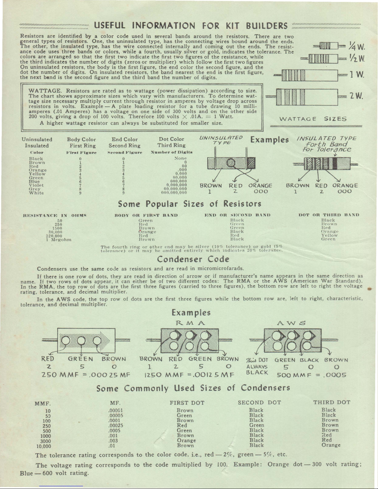
Resistors
general
The
ance
colors
the
On
dot
the
are
types
other,
code
are
third
indicates
uninsulated
the
number
next
band
identified
o~
resistors.
the
insulated
uses
three
arranged
resistors,
of
is
the
''"''
.....
so
the
digits.
second
''
,,,,,,
by a color
type,
bands
that
number
the
On
U S E F U L
One,
the
has
or
colors,
the
first
of
digits
body
insulated
figure
and
INFORMATION
code
used
uninsulated
the
wire
while a fourth,
two
indicate
(zeros
is
the
first
resistors,
the
third
in
several
type,
connected
the
or
multiplier)
figure,
the
band
has
internally
usually
first
the
end
band
the
bands
the
connecting
silver
two
figures
which
color
nearest
number
FOR
around
and
coming
or
of
follow
the
the
of
digits.
the
wires
gold,
the
the
second
end
is
KIT
resistors.
bound
out
the
indicates
resistance,
first
two
figure,
the
first figure,
BU
I L
There
around
ends.
the
tolerance. The
while
figures
and
the
DE
are
the
The
''''''''''''''''''''"''"'"'''''''''''''''''''
two
ends.
resist-
=l!ID=~w.
''"'''''''''''''''''''''''''''"''''''''''''''
Rs
=m~~~
--1~~~
F
'Aw
~1W.
WATTAGE.
The
chart
tage
size
resistors
amperes
200
volts,
A
higher
Uninsulated
Insulated
(·01or
Black
Brown
He
ct
Orang
e
Ye
llow
Green
Blue
Viol
et
Gr e y
Whit
e
llF:!"J!"TANCF:
~o.ooo
2
20,000
l Meg o
Condensers
If
the
In
there
If
two
RMA,
tolerance,
the A WS
name.
In
rating,
tolerance, and
Resistors
shows
necessary
in
(.01
250
1fi00
approximate
volts.
Amperes)
giving a drop
wattage
Body
First
1~~1rJ111t
0
l
2
3
4
5
fi
7
8
9
I~
OllM~
50
hm
use
is
one
row
rows
of
the
top
row
and
decimal
code, the
decimal
are
multiply
Example
has a voltage
of
resistor
Color
Ring
Ftg11re
the
same
of
dots, they
dots
appear
of
dots
multiplier
rated
as
to
sizes
- A
volts.
can
End
Second
~econd
which
through
plate
always
Color
.t""lgure
0
l
2
3
4
5
6
7
8
9
current
100
Some
DOD\'
The fo
urth
t o lf'r n n <'e ) 0 1·
code
as
are
, it
can
are
.
row
the
of
multiplier.
top
wattage
vary
resistor
loading
on
one
Therefore
be
Ring
Popular
OR
J<'JR!"T
G reen
Ht'<l
B ro
wn
6range
TI0d
Bro
wn
ring or
it
m
ay
resistors
read
in
either
first
three
dots
art
(power
with
resistor
side
100
substituted
Dot
Third
N_
u1nbt"r
oth<'r
h e o
dissipation)
manufacturers. To
in
amperes
for a tube
of
300
volts
Color
Ring
of
Dlglt11
No
,
000
0,
000
00,000
000.000
0,
000.000
00.000.000
000.000.0
HAND
(•nd
may
n1ittt·d
Condenser
and
are
read
direction
pc
of
figures
the
two
first
of
different
(carried
three
Examples
R.MA
by
voltage
volts
and
X .OlA. = 1
for
smaller
UNINSULRTED
ne
0
00
BROWN
00
1
Sizes
J<}ND
b e silver
e
ntir
e l y \Vhich
Code
in
micromicrofarads.
arrow
or
codes:
to
three
figures
according
determine
drop
drawing
on
the
other
Watt.
size.
TYPE'
RED
Resistors
of
~t:l'ONU H .
OR
Black
(;n·,·n
G
Bla~k
Hect
Black
(1
0%
t
olerance
indicatr·s
if
manufacturer's
The
figures), the
while the
to
10
2
n·~·
RMA
size.
wat-
across
milli-
side
ORANGE
n
) o r gold
20"1
bottom
=1111
WATTAGE
Examples
000
\ND
to
name
or
the
bottom
h ·ran
row
BROWN
(5%
cl·.
appears
AWS
(American War Standard).
row
are
are, left
AVVS
INSULAT£D
Forth
!Or
Tolerance
RED
1
DOT
in
left
z.
OR
the
same direction as
to
right
to
right, characteris
f=1w.
SIZES
TYPE
Band
""
ORAllluE
000
TlllRD
Dlac
Hro
H<>d
Orang-"
Y
ello
Green
HAND
k
w n
w
the voltage
•
tic,
RED
GREEN
BROW~
z 5 0
2SO
MMF
MMF.
10
5::>
100
250
500
1000
3000
10
,000
The
tolerance
The
voltage
Blue
- 600
volt
:::.
rating
rating
rating.
.000
ZS MF
Some
MF
.00001
.00005
.0001
.00025
.0005
.001
.003
.01
corresponds
corresponds
Commonly
.
BROWN
RED
GREEN
1 2 5 0
12SO
MMF
=.0012
Used
to
to
the
the
color
code
FIRST
multiplied
DOT
Brown
Green
Brown
Red
Green
Brown
Orange
Brown
code, i.e .,
13ROWl<J
SMF
Condensers
Sizes
of
SECOND
red-2o/r, green
by
100.
Example:
7~
DOT
ALWAYS
BLACK
Black
Black
Black
Green
Black
Black
Black
Black
- S
GREEN
5'
500MMF::::
DOT
o/r
, etc.
Orange
dot
BLACK
0
THIRD
- 300
BROWN
0
.0005
Black
Black
Brown
Brown
Brown
~ed
Red
Orange
volt
DOT
rating
;
Page 3
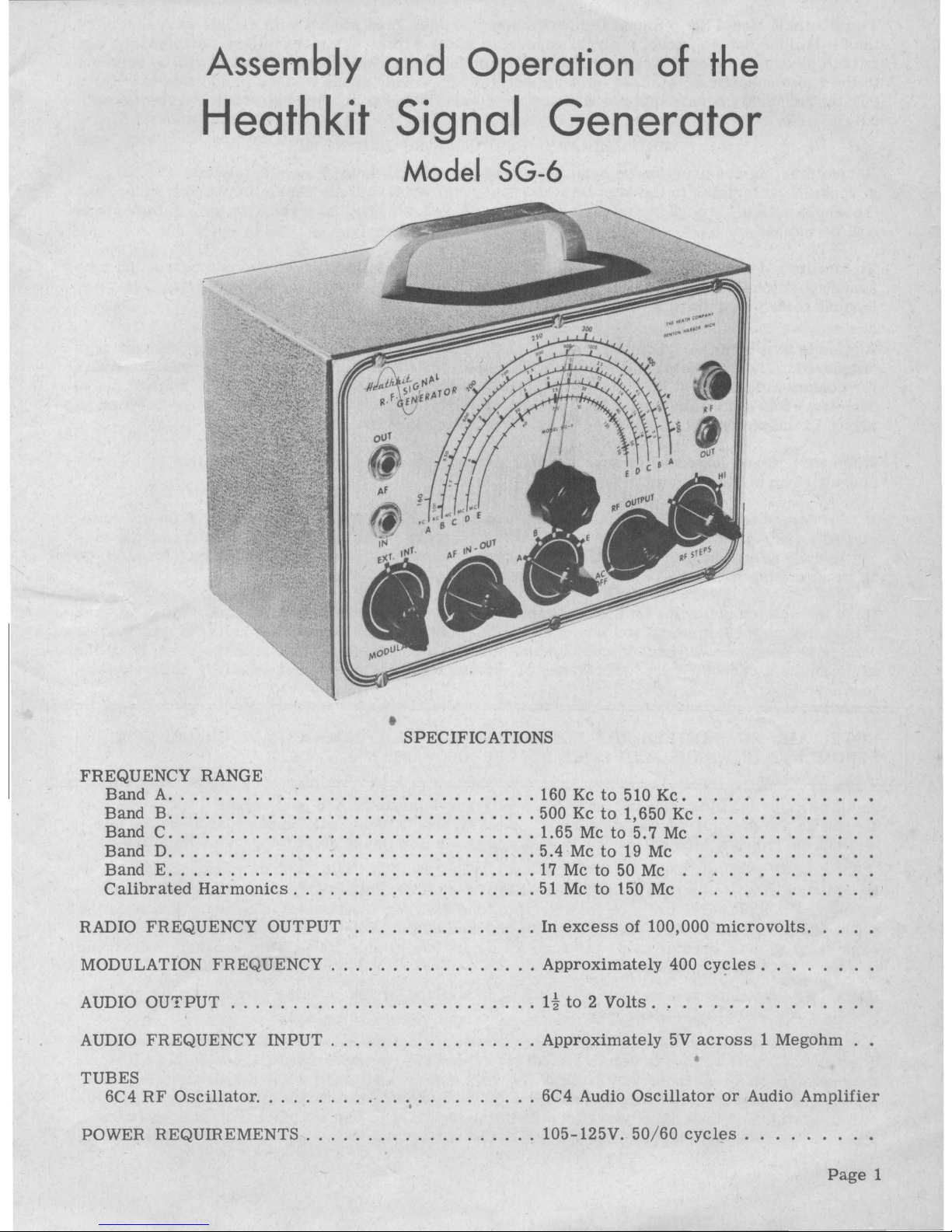
Assembly and Operation
of the
Generator
Heathkit
Signal
Model
SG-6
•
SPECIFICATIONS
FREQUENCY
RANGE
Band A ..........
:
...................
160 Kc
to
510
Kc.
Band B ..............................
500 Kc
to
1,650
Kc.
Band C ..............................
1.65 Mc
to
5. 7 Mc
Band D ..............................
5.4 Mc
to
19 Mc
Band E ..............................
17
Mc
to
50 Mc .
Calibrated
Harmonics
....................
51
Mc
to
150 Mc
RADIO
FREQUENCY
OUTPUT
...............
In
excess
of 100,000
microvolts.
MODULATION
FREQUENCY
.................
Approximately
400 cy<;:les.
AUDIO
OUTPUT
.........................
1~
to 2 Volts. , .....
.
AUDIO
FREQUENCY
INPUT
.................
Approximately
5V
across 1 Megohm
•
TUBES
6C4
RF
Oscillator
.......................
6C4 Audio
Oscillator
or
Audio
Amplifier
.
POWER
REQUIREMENTS
...................
105-125V.
50/60
cycles
....
.
Page
1
Page 4
The
Heathkit
Model SG-6 Signal
Generator
has
been
designed
so
that
with
simple
easy
assembly
the
kit
builder
can
construct a signal
generator
which
will
give
him
excellent
performance
and
is
both
pleasant
and
easy
to
use.
This
generator
has
been
engineered
so
that
it
will
be
valuable
to
the
radio
repairman,
ham,
or
experimenter
over
a wide
range
of
uses
in
addition
to
being
a
rugged
and highly
dependable
piece
of
test
equipment'made
of
the
highest
quality
parts
through-
out.
PRELIMINARY
INSTRUCTIONS
AND
NOTES
Before
starting
construction
be
certain
to
read
the
manual
through
completely
and
note
all
dia-
grams
and
pictorials.
In
the
step
by
step
procedure,
when
actually
assembling
and
wiring,
read
the
whole
article
through
(articles
are
numbered
1, 2, 3, etc.)
so
that
no
suggestions
in
the
article
will
be
missed.
To
facilitate
describing
the
location
of
parts,
solder
lug
positions
have
been
numbered,
and
tube
socket
positions
have
been
lettered
as
in
Figure
1.
Refer
to
this
figure
when
instruc'tions
say,
"mount
solder
lugs
4 and 5,
etc."
Also
note
that
both
the
schematic
diagram
and
Figures
5 and
11
show
all
switch
contact
lugs
numbered.
The
code
is
as
follows:
for
example,
M3
indicates, M for
modulation
switch
and
3
for
contact
solder
lug
3. BR6
means, B for
bandswitch, R for
rear
deck,
and 6
for
contact
lug
6.
Therefore
when mounting
switches,
be
sure
to mount
them
with
the
same
relative
position
as
shown
in
the
pictorials.
Likewise,
be
sure
and
mount
tube
sockets
as
pictured.
When
wiring,
and
instructions
say,
"connect
to
right
hand lug of
the
two
lug
terminal
strip,
etc."
consult
Figure 1 for
clarity.
It
is
recommended
that
tube
sockets
A and B on
figure
1 be
actually
labeled
A and B on
the
chas-
sis
with a pencil.
Also
writing
the
names
of
the
controls
on
the
inside
of
the
chassis
where
wir-
ing
is
done
will
reduce
the
possibility
of
wiring
to
improper
controls
by
mistake.
An
A,
B,
C,
D,
or E written
by
the
coils
on
the
sub-chassis
might
prove
helpful.
Read
the
note on
soldering
on
the
inside
of
the
back
cover.
Make a good
mechanical
joint
of
each
connection
with
clean
metal
to
clean
metal.
Use
only good
quality
rosin
core
radio
type
solder.
Pastes
or
acids
are
difficult
to
remove
and
minute
amounts
left
combine
with
moisture
from
the
air
forming a corrosive
product.
Weeks
or
months
later
corrosion
may
result
in
untimely
fail-
ure.
•
NOTE: ALL GUARANTEES ARE VOIDED
AND
WE
WILL NOT
REPAIR
OR SERVICE IN-
STRUMENTS IN WHICH ACID CORE SOLDER OR PASTES ARE USED.
Small
changes
in
parts
may
be ,
made
by
the
Heath
Company.
Any
part
supplied
will
work
just
as
well
as
the
part
for
which
it
was
substituted.
All
substitutions
will
be
of
equal
or
better
qual-
ity
than
the
original,
and
will
be
made
in
order
that a minimum
delay
will
occur
in
filling
your
order.
Resistors
aqd
controls
have a
tolerance
rating
of
plus
or
minus
20%
unless
otherwise
stated.
Therefore
a
lOOK
ohms
resistor
may
test
between
80K and 120K
ohms.
The
letter K stands
for
1,000
and M
for
1,000,000.
Thus.a
resistor
marked
90K=90,000
Ohms,
etc.
Frequently
conden-
sers
show
an
even
greater
variation
such
as
minus
50% to
plus
100%.
This
Heathkit
is
designed
to
accomodate
such
variation
.
The
tube
socket
pins
are
numbered
from 1 to 7 starting
at
the
spacing
and
reading
clockwise
when viewed
from
the
bottom.
See
Figure
2.
A
circuit
description
is
included
in a later
section
of
this
manual
so
that
those
with
some
knowl-
edge of
radio
will
be
able
to
obtain a clearer
picture
as
to
the
actual
workings
of
this
equipment
.
It
is
not
expected
that
those
with
little
radio
experience
will
understand
the
description
com-
pletely,
but
it
should
be
of
help
in
the
event
that
they
desire
to
become
more
familiar
with
cir-
cuit
operation
and
thus
learn
more
from
building
the
kit
than
just
the
placing
of
parts
and
wiring.
In
any
case,
this
section
points
out
the
use
of
the
various
controls
and
switches.
Page
2
Page 5
STEP
BY
STEP
ASSEMBLY
Use
of
bare
wire
where
indicated
will
facilitate
wiring,
but
insulated
wire
may
be
used.
Place
spaghetti
(insulated
sleeving)
over
bare
wires
on
condensers
or
resistors
where
riecessary
to
prevent
the
leads
from
accidentally
touching
other
bare
wires
or
metal
parts.
(S}
means
solder
·
(NS)
means
do
not
solder
yet
Begin
by
checking
the
parts
against
the
parts
list.
Identify
each
part,
using
the
charts
on
the
inside
of
the
cover
of
this
manual
where
necessary.
Thus,
you
will
avoid
throwing
away any
small
parts
with
the
packing.
MOUNTING
OF
PARTS
ON
CHASSIS
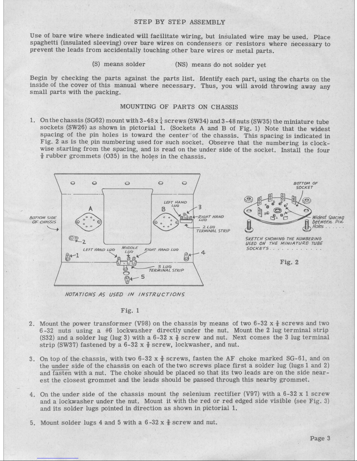
1. On
the
chassis
(SG62)
mount
with3-48x t screws
(SW34) and
3-48nuts
(SW35}
the
miniature
tube
sockets
(SW26}
as
shown
in
pictorial
1.
(Sockets
A and B of
Fig.
l}
Note
that
the
widest
spacing
of
the
pin
holes
is
toward
the
center
of
the
chassis.
This
spacing
is
indicated
in
Fig. 2 as
is
the
pin
numbering
used
for
such
socket.
Observe
that
the
numbering
is
clock-
wise
starting
from
the
spacing,
and
is
read
on
the
under
side
of
the
socket.
Install
the
four
t
rubber
grommets
(035) in
the
holes
in
the
chassis
.
BOTTOM SIDE
OF
CllA551S
'---.
.
Q
A
~
,._2.
LEFT
llAND
Ll.16
MJ_~~LE
RIGHT
HAND
LU<i"
,__©_..-_i ____
__
'¥::.~z,~~r
;,,.
fJj
@...-s
NOTATIONS
A5
USED
IN
IN>TRl/CTION~
Fig.
1
4
BOTTONI
OF
SOCKET
Wtde>f
5/JaCif:tl}
Jj
between
Pin,
®Holes
....
_.
5J<ETCH 5HOWIN6
THE
NUMBERING
/JSED
Oii
THE
MINIATURE
TUBE
SOCKETS .... _ ...
Fig.
2
2. Mount
the
power
transformer
(V98) on
the
chassis
by
means
of two
6-32
x t
screws
and two
6-32
nuts
using
a #6
lockwasher
directly
under
the
nut. Mount
the 2 lug
terminal
strip
(S32) and a
solder
lug
(lug 3) with a
6-32
x t
screw
and nut. Next
comes
the 3 lug
terminal
strip
(SW37)
fastened
by a -6-32 x t
screw,
lockwasher,
and nut.
3.
On
top
of
the
chassis,
with two
6-32
x t
screws,
fasten
the
AF
choke
marked
SG-61,
and
on
the
under
side
of
the
chassis
on
each
of
the
two
screws
place
first a solder
lug
(lugs 1 and
2)
and
fasten
with a nut.
The
choke
should
be
placed
so
that
its
two
leads
are
on
the
side
near-
est
the
closest
grommet
and
the
leads
should
be
passed
through
this
nearby
grommet.
4. On
the
under
side
of
the
chassis
mount
th~
selenium
rectifier
(V97) with a
6-32
x 1
screw
and a lock:washer
under
the
nut. Mount
it
with
the
r.ed
or
red
edged
side
visible
(see
Fig.
3)
and
its
solder
lugs
pointed
in
direction
as
shown
in
pictorial
1.
5. Mount
solder
lugs 4 and
5 with a
6-32
x t
screw
and nut.
Page
3
Page 6
MOUNTING
OF
PARTS
ON
FRONT
PANEL
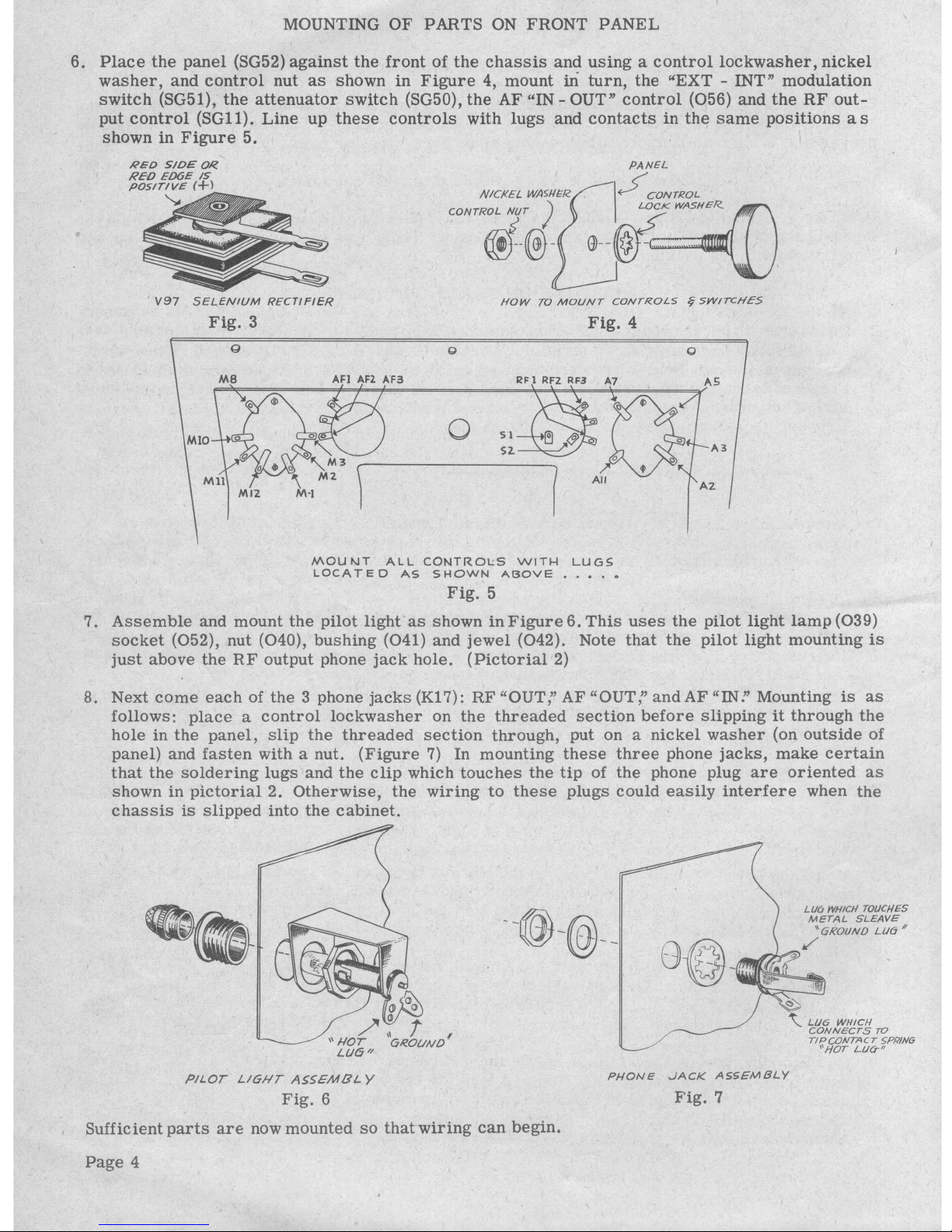
6.
Place
the
panel
(SG52)
against
the
front
of
the
chassis
and
using a control
lockwasher,
nickel
washer,
and
control
nut
as
shown
in
Figure
4, mount iri
turn,
the
"EXT
- INT"
modulation
switch
(SG51),
the
attenuator
switch
(SG50),
the
AF "IN - OUT"
control
{056) and
the
RF
out-
put
control
(SGll).
Line
up
these
controls
with
lugs
and
contacts
in
the
same
positions
as
shown
in
Figure
5.
•
RED
S!DEOR
RED
ED6E
IS
POSITIVE
(+l
""
V97
SEL.ENtUM
RECTIFIER
Fig.
3
NICKEL
WA91£R
CONTROL
1T
)
@--®-
PANEL
\
~CONTROL
LOCK
WASHER..
~--~--Mmfffl
HOW
TO
MOUNT
CONTROLS
~SWITCHES
Fig.
4
0
SI
n
S2.
,--~~~~~~~~--..
All
0
A3
A2
MOUNT
ALL
CONTROLS
WITH
LUGS
LOCATED
AS
SHOWN
AC30VE
•••••
Fig.
5
7.
Assemble
and
mount
the
pilot
light
as
shown
in
Figure
6.
This
uses
the
pilot
light
lamp
{039)
socket
(052), nut (040),
bushing
(041)
and
jewel
{042). Note
that
the
pilot
light
mounting
is
just
above
the
RF
output phone
jack
hole.
(Pictorial
2)
8. Next
come
each
of
the
3 phone
jacks
{Kl 7):
RF
"OUT;'
AF
"OUT:'
and
AF
"IN!'
Mounting
is
as
follows:
place a control
lockwasher
on
the
threaded
section
before
slipping
it
through
the
hole in
the
panel,
slip
the
threaded
section
through,
put on a
nickel
washer
(on
outside
of
panel) and
fasten
with a nut.
(Figure
7) In
mounting
these
three
phone
jacks,
make
certain
that
the
soldering
lugs
and
the
clip
which
touches
the
tip
of
the
phone plug
are
oriented
as
shown
in
pictorial
2.
Otherwise,
the
wiring
to
these
plugs
could
easily
interfere
when
the
chassis
is
slipped
into
the
cabinet.
--@-@--
L/16
WHICH
TOI/CHES
METAL
SLEAVE
"GROUND
LU6
II
8@-W.1111https://manualmachine.com/
...
~
\__
LUG
WHICH
CONNECTS
TO
TIPU)NTACT
5PR!N6
''HOT
Lll<T//
PILOT
LIGHT
ASSEMBLY
Fig.
6
PHONE
JACK
A55£MBLY
Fig.
7
Sufficient
parts
are
now mounted
so
that
wiring
can
begin.
Page
4
Page 7
WIRING
PROCEDURE
9.
Wire
in
the
power
transformer
(V9S)
as
shown
in
pictorial 1 and
as
follows:
twist
the
two
black
leads
together,
cut
them
to
proper
length,
and
fasten
them
to
the
two
outside
lugs
of
the
three
lug
terminal
strip
(NS).
Fasten
one
yellow
lead
to
solder
lug
1 (NS)
and
the
other
yel-
low
lead
to
pin 4 of
tube
socket
A (NS). One
red
lead
goes
to
solder
lug
1 (NS)
and
the
other
red
lead
connects
to
the
bottom
lug
{lug
furthest
from
the
red
edged
insulator
piece)
of
the
selenium
rectifier
{S).
Wire
from
pin
4 of
socket A (S)
to
pin
4 of
socket
B (NS).
Note
that
this
wire
follows
along,
and
is
close
to,
the
bend
of
the
chassis.
Wire
from
pin 4 of
socket
B
{S)
to
the
pilot
light
"HOT"
solder
lug
(S)
(see
Fig.
6)
passing
the
wire
through
the
nearby
rubber
grommet.
Ground
the
pilot
light's
"GROUND"
solder
lug
to
the
pilot
light
frame
(S).
Wire
from
pin
3 of
socket
B (NS)
to
solder
lug
3 (NS).
Wire
from
pin
3 of
socket
A (NS)
to
solder
lug
2 (NS).
10.
To
the
left
hand
lug
of
the 3 lug
terminal
strip,
fasten
one
lead
of
a .001
MFD
condenser
(SG46) (NS)
and
this
condenser's
other
lead
connects
to
solder
lug
5 {NS).
Note
that
lead
near
"outside
foil"
or
black
ring
marking
on
body
of
condenser
is
the
lead
which
goes
to
the
solder
lug
(ground).
Hereafter,
whenever
condensers
are
grounded,
have
the
outside
foil
lead
as
the
grounded
lead.
Connect
the
other
.001
MFD
condenser
to
the
middle
lug
of
the 3 lug
terminal
strip
(NS)
and
its
outside
foil
lead
to
solder
lug
5 (S).
11. Note
that
the
"RF
output -AC
off"
control
has
two
solder
lugs
protruding
from
the
back
of
it.
Twist
two
pieces
of
wire
together,
and
wire
from
control's
back
lugs,
(lugs
Sl
and
S2,
Fig.
5)
(S)
to
the
middle
{NS)
and
right
hand
solder
lugs
(S)
of
the 3 lug
terminal
strip.
Refer
to
pic-
torial
1.
12.
Wire
from
the
upper
lug
(the
lug
nearest
the
red
edge
insulator
piece)
of
the
selenium
rec-
tifier
(S)
to
the
right
hand
lug
on
the
two
lug
terminal
strip
(NS).
To
this
right
hand
lug
also
connect
one
lead
(on
the
side
marked
positive
or
with
a+++
marking)
of
the
dual
20
MFD
con-
denser
(K13) (NS).
The
single
lead
at
the
other
end
of
the
condenser
goes
to
solder
lug4
(S).
The
other
positive
lead
goes
to
the
left
hand
lug
of
the
two
lug
terminal
strip
(NS).
Wire
the
2700
resistor
(KlO)
between
the
right
hand
lug
of
the 2 lug
terminal
strip
(S)
and
the
left
hand
lug
(NS).
To
this
left
hand
lug
also
connect
one
lead
of
the
5600
resistor
(Gl2)
(S)
and
the
resistor's
other
lead
to
pin 5 of
socket
B (NS).
Wire
from
pin
5 of
socket
B (S)
to
pin
1 of
socket
A (S).
This
wire
follows
along
the
bend
of
the
chassis.
13.
SOCKET
B:
Wire
to
socket B as
follows:
to
pin 1 connect
one
lead
of
a .01
condenser
(T13)
{S)
and
fasten
the
outside
foil
lead
to
solder
lug
3 (S).
Fasten
to
pin
6 a
lead
of
the
27K
re-
sistor
(FM36) (NS)
and
connect'
the
other
lead
of
this
resistor
to
pin
3 (S).
14.
SOCKET
A:
Socket A wiring
is
as
follows:
to
pin 3 connect
one
leadofa330resistor
(AR25)
(NS)
and
the
resistor's
other
lead
to
pin
7 (S).
To
pin 3 connect
one
lOOK
resistor
lead
(012)
(S)
and
the
other
lead
goes
to
pin
6 (NS).
Wire
from
pin 5 (S)
to
the
"EXT -INT"
modulation
switch
contact
M12(S).
Connect
one
lead
of a .05
condenser
(AR2S}
to
pin
6 (S)
and
the
out-
side
foil
lead
of
this
condenser
fastens
to
"EXT
- INT."
modulation
switch
contact
M2
{S).
15. MODULATION SWITCH:
Considering
now
the
wiring
of
the
modulation
switch
(see
Fig.
5
showing
numbering
of
switch
contacts)
wire
as
follows:
connect
a 390K (SG54)
resistor
be-
tween
lugs
MS
(NS)
and
MlO
(S)
and
be
certain
that
the
resistor
leads
are
passed
through
the
sold.er
lug
holes
in
direction
as
shown
in
pictorial,
otherwise
difficulty
might
be
encountered
when
trying
to
slip
the
chassis
into
the
cabinet.
To
switch
lug
Mll
fasten
a .1
condenser
{slip
spaghetti
over
the
condenser
lead)
(049)
(NS)
and
the
condenser's
outside
foil
lead
goes
to
solder
lug 1 (NS).
To
lug
M3
connect
one
lead
of a .02
condenser
(use
spaghetti)
(025)
(NS)
and
fasten
the
outside
foil
iead
to
solder
lug
1 (S).
Twist
the
leads
of
the
AF
choke
and
con-
nect
one
of
them
to
contact
Mll
(S)
and
the
other
one
to
contact
lug
M3
(S).
Connect
one
lead
of a .01
condenser
(T13)
to
contact
lug
Ml
(S)
and
the
conden'ser's
other
lead
to
solder
lug
AF2
(NS)
of
AF
"IN-OUT"
control.
From
contact
lug
MS
connect a lead
of
a .01
condenser
(S)
and
the
outside
foil
lead
goes
to
lug
AFl
(NS).
16.
AF
IN-OUT
CONTROL:
To
lug
AF3
fasten a wire
(S)
and
connect
it
to
solder
lug
2 (S).
Con-
nect a piece
of
wire
to
AF2
(S)
pass
it
through
the
nearby
grommet,
and
fasten
to
the
AF
"OUT"
phone
jack
"HOT"
lug
(Fig.
7).
To
AFl
connect a piece
of
wire
(S),
pass
it
through
the
nearest
grommet,
and
fasten
it
to
the
AF
"IN" phone
jack
"HOT"
lug
(S).
Page
5
Page 8
17.
RF
OUTPUT CONTROL:
To
lug
RFl
connect
(use
spaghetti) a lOK
resistor
lead
(Oll)
(S)
and
the
resistor's
other
lead
goes
to pin 7 of
socket
B (NS).
Connect a short
piece
of
wire
from
lug
RF2
(S)
to
lug
A7
(NS).
Fasten a piece
of
stiff
bare
wire
to
lug
RF3
(S),
slip
it
through
lug
All
(NS),
pass
the
wire
through
the
nearby
grommet,
and
then
connect
it
to
the
"GROUND"
lug
of
the
RF
"OUT"
jack
(S).
18. ATTENUATOR SWITCH:
To
lug
A.7
connect a lead
of a
620-680
resistor
(SG53)
(S)
and
the
resistor's
other
lead
fastens
to
contact
A5
(NS).
Connect
the
other
620-680
resistor
between
lugs
A5
(NS)
and
A3
(NS)
making
certain
that
the
resistor
does
not
protrude
so
that
it
will
interfere
with
slipping
the
chassis
into
the
cabinet.
Connect
a 47
ohm
resistor
(TS29)
be-
tween
solder
lugs
A5
(S)
and
All
(NS).
The
other
47
ohm
resistor
goes
between
contact
lugs
A3
(S)
and
All
(S).
Connect a length
of
wire
to
lug
A2
(S)
pass
it
through
the
nearby
grommet,
and
fasten
it
to
the
RF
"OUT"
jack's
"HOT"
lug
(S).
19.
Pass
the
line
cord
(078)
through
the
grommet
in
the
very
back
of
the
chassis,
and knot
the
cord
at a convenient
length
so
that
by
pulling
on
the
cord, a strain
will
not
be
placed
on
con-
nections
of
cord
to
equipment.
These
connections
are
as
follows: one
lead
of
the
cord
goes
to
the
left
hand
solder
lug
of
the 3 lug
terminal
strip
(S)
and
the
other
lead
connects
to
the
middle
solder
lug
of
the 3 lug
terminal
strip
(S).
THE
TURRET
COIL ASSEMBLY
AND
SUB
CHASSIS WIRING
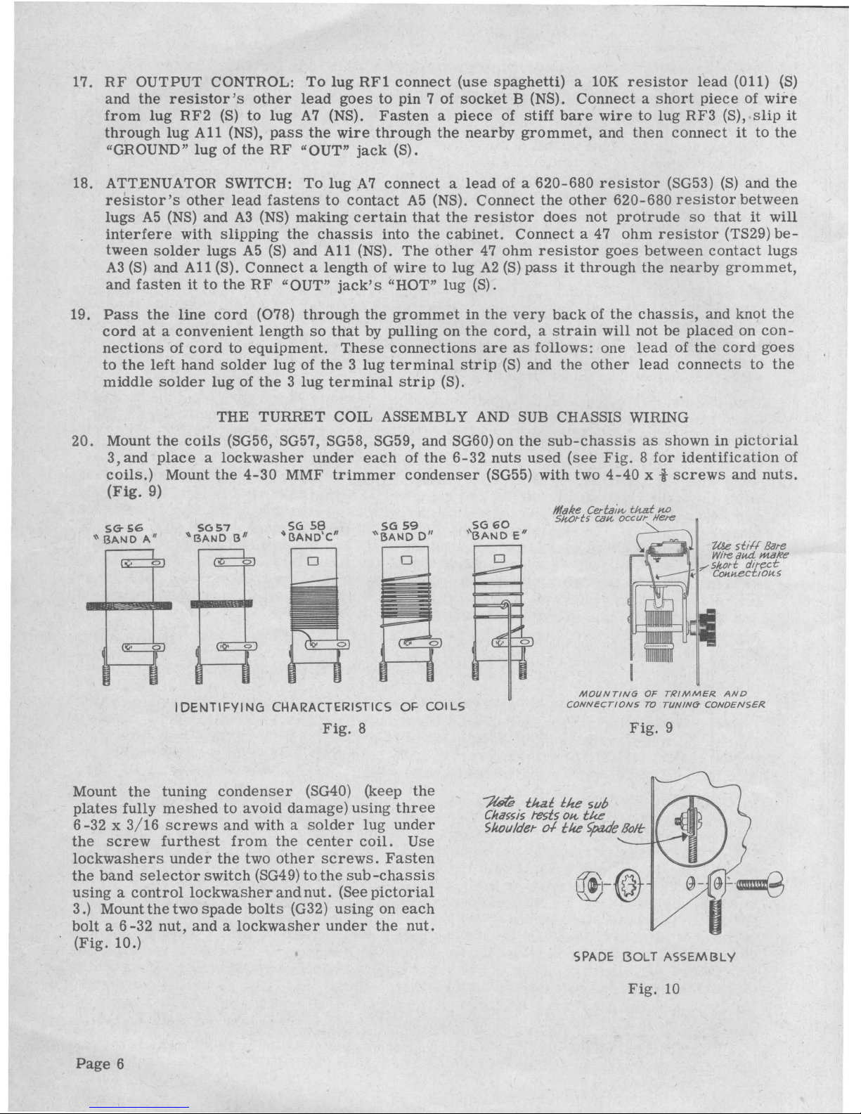
20. Mount
the
coils
(SG56, SG57, SG58, SG59,
and
SG60) on
the
sub-chassis
as
shown
in
pictorial
3, and
place a lockwasher
under
each
of
the
6-32
nuts
used
(see
Fig. 8 for
identification
of
coils.)
Mount
the
4-30
MMF
trimmer
condenser
(SG55)
with
two
4-40
x t
screws
and
nuts.
(Fig.
9)
SG-56
SCJS7
"BAND
A''
"BAND
13
11
SG
58
"BAND'C"
SG
59
''BAND
D"
IDENTIFYING
Cl-\ARACTERISTICS
OF
COILS
Fig.
8
Mount
the
tuning
condenser
(SG40) (keep
the
plates
fully
meshed
to
avoid
damage)
using
three
6-32 x 3/16
screws
and
with a
solder
lug
under
the
screw
furthest
from
the
center
coil.
Use
lockwashers
under
the
two
other
screws.
Fasten
the
band
selector
switch
(SG49)
to
the
sub-chassis
using a control
lockwasher
and
nut.
(See
pictorial
3
.)
Mount
the
two
spade
bolts
(G32)
using
on
each
bolt a 6-32
nut,
and a lockwasher
under
the
nut.
(Fig.
10.)
Page
6
SG60
''BAND
E"
D
MOUNTING
OF
TRIMMER
AND
CONNECTIONS
TO
TUNIN6
CONOEN5£R
Fig.
9
~
tkat
lite svb
Chassis
tests
OH..
tt<.e
Shoulder
o.f
tlte
~e
Bolt
(@-@
SPADE
!30LT
ASSEMBLY
Fig.
10
Page 9

NOTE:
IN
ARTICLES
21 AND 22, IN
ALL
CASES USE
STIFF
BARE
WffiE
A good way
to
prepare
the
supplied
length
of
bare
wire
for
wiring
purposes
is
to
uncoil
the
wire
and
place
one
end
in a vise,
for
instance,
and
with a pair
of
pliers,
stretch
the
wire
about
t".
The
stretching
cold-works
the
wire
so
that
it
becomes
stiffer
(therefore
better
for
wiring),
and
it
also
removes
kinks.
21.
Note
carefully
pictorial 3 showing
the
wiring
of
the
coils
to
the
selector
switch
and
the
wiring
of
the
selector
.switch.
Observe
Fig.
11
carefully
for
contact
numbering.
FRONT
Bf:IZ~DECK)
o D o
BFI
BF6
BF
BFS
15F3
BF4
REAR'
'
OECI(
-.....J
·:.~~
...
B~RS
BR3
BR4
NUMBERIN<Jr
OF
CONTACT
WGS
ON
SELECTO/l.
SWITCH
Fig.
11
----
.,,,-
Plastic
/Mi,-cal:or
it'~
Leave
clet11'ilkCe
betw~
/Hdicat~
a.Ht.I
PaH.el
METHOD
IN
WHICH
INDICATOR.
ASSEMBLY
ANO
l<NOB
MOUNT
ON
VARIABLE
TUNING
CONDENSER
SHAFT
•••••••••
°
Fig.
12.
Make
connection
from
the
selector
switch
rear
deck
contact
lug
BR12 (S)
to
the
front
deck
contact
lug
BF12
(S)
and
continue
the
wire
to
the
nearby
solder
lug
on
the
sub-chassis
(S).
SWITCH
AND
COIL
CONNECTIONS:
Bottom
lug
(if
present)
of
coil
E
leave
blank.
(The
bottom
lug
is
the
lug
nearest
the
spade
bolts.)
The
wire
tapped
about
midway
of
coil E con-
nect
to
BF5
(S).
Bottom
lug
of
coil D (S)
to
BF4
(S).
Bottom
lug
coil
C (S)
to
BF3
(S).
Bottom
lug
coil B (S)
to
BF2
(S).
Bottom
lug
coil
A (S)
to
BFl
(S).
Top
lug
coil
E (S)
to
BR5
(S).
Top
lug
coil
D (S)
to
BR4
(S).
Top
lug
~oil
C
(S)
to
BR
3 (S).
Top
lug
coil
B (S)
to
BR2 (S).
Top
lug
coil
A (S)
to
BRl
(S).
Make
certain
that
none
of
the
wires
of
above
connections
touch
or
could
touch
each
other
with
slight
jarring.
From
BR6
(NS)
connect a wire
to
the
nearest
stator
solder
connection
of
the
tuning
condenser
(S)
(see
pictorial
3).
(Stator
plates
are
those
plates
of
the
condenser
which
do
not
rotate,
that
is,
they
are
the
stationary
plates.)
See
Fig.
9
and
make
the
short
direct
connection
from
the
trimmer
condenser
(S)
to
the
nearest
stator
plate
solder
lug
(S).
Connect
from
the
trimmer
(S)
to
the
tuning
condenser
frame
(S).
Use
bare
wire
for
these
two
connections.
22.
The
sub-chassis
should
nowbe
mounted
on
the
main
chassis
by
means
of
the
spade
bolts
and
two
6-32
nuts, a lockwasher
being
placed
under
each
nut.
Connect
the
150 MMF
condenser
(AR26)
between
BR6 (S)
and
pin 6 of
tube
socket
B (S).
Make
a
short
direct
connection
from
BF6
(S)
to
pin
7 of
socket
B (S).
The
wiring
of
the
signal
generator
is
now
completed.
23.
Place
the
five
pointer
knobs
(051)
on
the
control
shafts
and
fasten
each
with
the
small
set
screw
that
is
in
the
knob.
Fully
mesh
the
variable
tuning
condenser,
and
with a set
screw
(TS55)
fasten
(do
not
tighten
down
the
screw
very
hard)
the
indicator
assembly
(SG45)
on
the
control
shaft
so
that
the
hair
line
coincides
with
the
left
end
of
the
dial
scale.
Be
sure
that
the
plastic
indicator
does
not
rub
against
the
panel
but
rather
has a little
clearance.
Fasten
knob SG44
on
the
tuning
condenser
shaft
and
leave a slight
clearance
between
the
knob
and
the
plastic
indicator.
Note FigurP. 12.
Page
7
Page 10

24.
Observe.that
the
phone plug (V41)
cap
unscrews
from
the
plug
tip
assembly.
Assemble
the
test
lead
as
shown
in
Fig.
13
checking
closely
to
see
that
the
connection
of
the
inner
conductor
goes
to
the
proper
solder
lug
of
the
phone plug.
Screw
the
cap
over
the
plug
before
attaching
the
alligator
clips
(V44).
Plug
the
6C4
tubes
into
their
sockets
and
the
generator
is
ready
for
test.
Fig.
13
CALIBRATION
DROP
OF
SOLDER
METALLIC
COATING
MAY.IM
UM
MIN
IM
UM
CAPACITANCE
CAPACITANCE
!D£NT/t=Y/N6
TRIMMER
FOR
MAX/MUNI
AND
MINIMUM
CAPACITANCE
5ETTIN65
Fig
. 14
On a
receiver,
tune
in a
strong
station
of known
frequency
between
1,200
and
1,600
Kc.
Place
the
test
lead
from
the
generator
close
to
the
antenna
of
the
receiver
and
tune
the
generator
to
approximately
the
same
frequency.
This
will
cause a whistle
in
th~
1
receiver.
The
lowest
pitch
whistle
(zero
beat)
indicates
that
the
signal
generator
and
station
are
on
the
same
fre-
quency. Now
set
the
generator's
plastic
indicator
to
read
the
same
frequency
as
the
station,
and
adjust
the
trimmer
to
again
give
zero
beat.
The
trimmer
should
be
nearly
in
the
minimum
ca-
pacity
position.
(Fig.
14).
The
calibration
will
now hold
quite
accurately
on
all
bands.
The
calibration
on
the
higher
frequency
bands
may
be
upset
by
excessively
long
leads
on .
the
tuning
assembly.
Such
variations
in
inductance
cannot
be
compensated
for
by
trimmer
adjust-
ment.
If
the
trimmer
is
in
the
minimum
capacity
position
before
zero
beat
can
be
obtained,
there
is
an
excessive
amount
of
distributed
capacity
due to
wiring
in
the
tuning
circuits.
Make
sure
all
the
"hot"
leads
(from
the
top
lug
on
the
coils
to
the
switch,
and
from
the
switch
to
the
tuning
conden-
ser
and
trimmer)
are
at
least a quarter
inch
away
from
the
metal
chassis
and
all
other
wiring.
After
calibration
is
completed,
place
the
rubber
feet
on
the
cabinet
( T32 )
(Fig.
15)
and
fasten
on
the
carrying
handle
(079)
using
two
10-24
x t
handle
screws
(030).
Slio
the
chas-
sis
into
the
cabinet
and
using
#6
xt
sheet
metal
screws
{0102)
fasten
the
panel
to
the
cabinet.
In
the
back
of
the
cabinet,
fasten
the
chassis
to
the
cabinet
using
sheet
metal
screws.
ACCURACY
Fig.
15
Any
signal
generator
is
designed
as a convenient
and
controllable
source
of
modulated
or
un-
modulated
signals.
No
signal
generator
is
designed
as a frequency
standard
·.
Expensive
stand-
ard
signal
generators
have
fairly
accurate
(3-20%)
attenuators
which
control
the
output
voltage,
and
the
calibration
accuracy
is
rarely
closer
than
1%.
The
Heathkit
generator
may
be
expected
to
fall
within
2-3% of
the
frequency
calibration,
which
is
quite
satisfactory
for
service
work
and
alignment.
In
receiver
alignment,
the
frequency
at
which
the
particular
adjustment
is
made
is
rarely
critical,
but
the
adjustment
itself
for
maximum
signal
output
from
the
receiver
is .fre
-
quently
quite
critical.
Page
8
Page 11

For
accurate
calibration
of
home
built
receivers
or
equipment
proceed
as
follows:
make a rough
calibration
with
the
signal
generator.
Then,
with a
receiver,
tune
in
WWV
(Bureau
of
Standards)
at
2. 5,
5,
or
10 Mc. Set
the
signal
generator
to a
suitable
sub
harmonic
such
as
for
instance
500
Kc, and
adjust
the
generator
for
zero
beat.
Now
the
harmonics
of
the
signal
generator
occur
very
accurately
every
500
Kc
and
these
harmonics
may
be
used
to give
accurate
calibration
points
at
500
Kc
intervals
such
as
2,500'Kc,
3,000 Kc, 3,500 Kc, 4,000 Kc,
etc.
These
known
frequency
points
can
be
marked
on
the
dial
of
the
equipment
being
calibrated.
The
object
of
the
rough
calib:t'ation
is
merely
to
furnish a means
of
identifying
for
example
the
3,000 Kc point
from
the
2,500 Kc
or
3,500 Kc
points.
For
calibration
of
higher
frequency
equipment, a choice
of a
higher
sub
harmonic
will
reduce
confusion
between
the
multitude
of
harmonics
and
will
also
insure
adequate
signal
strength.
When
checking
the
calibration
accuracy
of
the
Heathkit
Generator,
the
most
convenient
standards
of
comparison,
of
sufficient
accuracy,
are
broadcast
stations
of
knownfrequency.
Crystal
oscil-
lators
of
standard
frequencies,
when
zero
beat
against
WWV,
are
also
convenient
to
use,
if
avail-
able.
The
use
of
receiver
dial
calibrations
is
frequently
not of
sufficient
accuracy
to
warrant
consideration.
USE OF
R.F.
SIGNAL GENERATOR
This
Signal
Generator
can
be
used
to
align
radio
receivers.
It
furnishes a source
of
radio
fre-
quency
or
modulated
radio
frequency
by
means
of
signal
generator
fundamental
frequencies
be-
tween
160
Kilocycles
and
52
Megacycles
(1
Megacycle=l
,000
Kilocycles)
and
useful
calibrated
har-
monics
of
the
signal
generator
furnish
output
to
over
150
Megacycles.
Wherever
possible,
the
recommendations
of
the
manufacturer
of
the
radio
being
aligned
should
be
used.
When
this
is
not
available,
the
following
procedure
can
be followed.
Output
Indication.
With
the
new
types
of
receivers,
especially
those
using
AVC
(automatic
vol-
ume
control), a visual
means
of
indicating
resonance
is
desirable.
If
convenient,
in
all
receiver
alignments,
the A VC
should
be
disabled
during
the
process
of
alignment.
Otherwise a signal
weak
enough to
not
operate
the A VC
should
be
used
.
IF
Alignment.
Connect
the
signal
generator
shield
to
chassis
and
clip
the
shielded
wire
to
the
signal
grid
terminal
on
the
converter
tube
socket.
Set
the
signal
generator
to
the
IF
frequency
required.
RMA
standard
is
455 Kc, but
other
frequencies
like
262 and 175 Kc
are
sometimes
used.
Adjust
generator
output
for
minimum
readable
output
indication.
Adjust
IF
transformers
starting
with
the
one
nearest
the
second
detector
and
working
forward.
The
adjustment
mecha-
nism
consists
generally
of two
screws
which
operate
trimmer
condensers,
or
iron
cores
inside
the
coils.
They
may
be
located
on top,
on
the
side,
or
on
the
top
and
bottom
of
the
IF
transfor-
mer.
Turn
the
adjusting
screw
for
maximum
output,
reducing
the
signal
generator
output
if
nec-
essary
to
keep
the
output
indicator
from
going off
scale.
Oscillator
Alignment.
With
the
generator
connected
as
above,
set
the
generator
dial
to
the
high-
est
frequency
marked
on
the
receiver
dial
(1,600
or
1,720 Kc).
Set
the
receiver
dial
to
this
same
frequency.
Adjust
the
receiver
oscillator
trimmer
to
bring
in
the
signal.
An
additional
adjustment
is
often
provided
in
the
form
of a
padding
condenser
or
an
iron
core.
This
is
gen-
erally
adjusted
at
600 Kc
and
its
final
adjustment
is
made
later.
RF
Alignment.
Using
a 200 MMF
condenser
between
generator
and
antenna
post,
set
receiver
and
generator
to 1,400 Kc.
Adjust
antenna
(and
RF,
if
used)
trimmer
(frequently
located
on
the
tuning
condenser)
for
maximum
output.
Set
generator
to 600 Kc
and
"rock"
tuning
condenser
through
the
signal
while
adjusting
the
oscillator
padder
for
maximum
output
at
resonance.
For
receivers
with a
loop
antenna,
couple
the
signal
through a single
turn
loop
connected
to
the
generator
output.
Tuned
radio
frequency
receivers
are
aligned
as
shown
under
RF
Alignment.
Page
9
Page 12

The
AF "Output"
source
can
be
used
to
test
audio
amplifiers.
To
make
such
tests,
plug
the
test
lead
into
the
AF "OUT"
jack
and
throw
the
modulation
switch
to
internal
position.
Connect
the
alligator
clip
on
the
braided
lead
to
the
chassis
of
the
amplifier
under
test.
The
alligator
clip
on
the
center
conductor,
when
touched
to
the
grid
(through
a .05 MFD
condenser)
of
the
audio
stage
should
produce
an
audible
output
of
approximately
a 400
cycle
note
if
the
stage
is
ope
rat
-
ing
correctly
and
is
connected
to
a good
speaker.
OUTPUT
VOLTAGE
The
RF
signal
strength
going
into
the
output
control
depends
upon
the
strength
of
oscillation
of
the
6C4
oscillator.
In
all
variable
frequency
oscillators,
the
amplitude
will
vary
with
the
tuning
condenser
setting.
With
careful
design,
the
variation
may
be
minimized.
In
the
Heathkit
signal
generator,
the
variation
is
kept
down
to a ratio
of
about
2~
to 1 on
each
band,
except
on
band
E
where
the
L/C
(inductance
to
capacitance)
ratio
becomes
sufficiently
unfavorable
that
oscil-
lation
may
stop
with
the
tuning
condenser
nearly
fully
closed.
However,
sufficient
overlap
is
provided
to
insure
complete
frequency
coverage.
The
maximum
output
on
all
bands
is
usually
greater
than
100,000
microvolts.
CIRCUIT DESCRIPTION
Incorporated
in
the
design
are
the
following
features:
the
RF
oscillator
coils
are
prec1s10n .
wound
and
adjusted
to
calibration
before
shipment,
thereby
assuring
maximum
accuracy.
The
coils,
bandswitch,andthe
tuningcondenser
all
mount
as a turret
assembly
so
as
to
offer
the
ad-
vantage
of
short
wiring
leads
and
easy
mounting
of
parts.
To
prevent
tuning
past a desired
RF
output
signal
when
operating
the
generator,
the
tuning
con-
denser
has a vernier
drive
(3
revolutions
of
the
outside
knob
produce
~revolution
of
condenser
rotors).
This
condenser
varies
the
capacitance
in
the
Hartley
osciilator
thus
giving
the
band
cove-rage.
The
individual
bands
are
selected
by
means
of
the
bandswitch
which
connects
any
one
of
the 5 coils
acting
as
inductance
in
the
Hartley
oscillator.
The
audio
oscillator
is a Colpitts
oscillator
which
produces
approximately
a 400
cycle
note
of
good wave
form.
This
oscillator
has
the
advantage
of
being a source
of audio
output
by
merely
throwing
the
modulation
switch
to
"INT"
position
and
plugging into
the
AF
output
jack.
This
handy
source
of
AF
can
be
used
for
testing
of
audio
amplifier
stages,
etc.
When
the
modulation
switch
is
in
the
"INT"
position,
the
AF
oscillator
modulates
the
RF
output.
External
modulation
can
be
obtained
by plugging
the
external
source
into
the
AF "IN" phone
jack
on
the
panel
and
throwing
the
modulation
switch
to
"EXT"
position.
Design
is
such
that
external
modulation
of
small
signal
strength
from
a high
impedance
source
can
be
used,
and
thus
the
ver-
satility
of
the
instrument
is
increased.
The
6C4
tube
which
is
in
the
audio
oscillator
circuit
on
"INT"
modulation
position,
on
"EXT"
position
acts
as
an
audio
amplifier
to
the
external
modula-
tion.
The
RF
output
circuit
is
of low
impedance.
This
is
accomplished
by
the
use
of
cathode
coupling
to
the
output
jack.
The
level
of
RF
output
is
varied
by
means
of
the
RF
steps
switch
located
on
the
panel.
On
this
switch,
"HI"
indicates
high
RF
output
(therefore
low
attenuation).
The
middle
position
of
the
switch
produces a lower
RF
output
and,
the
maximum
C'ounterclockwise
position
gives
the
lowest
RF
output.
(Maximum
attenuation).
With low
attenuation,
the
smallest
amount
of
resistance
is
in
the
cathode
coupling
circuit
to
the
RF
output
jack.
In
the
middle
position
of
the
steps
switch, a single
pi
section
is
added and
for
highest
attenuation, a second
pi
network
is
thrown
into
the
circuit.
AC
line
input
is
connected
to a high
quality
varnish
impregnated
power
transformer.
A
ruby
red
pilot
light
on
the
front
panel
acts
as a convenient
indicator
as
_to
whether
power
is
on
or
off.
The
1
lOV
power
line
has
both
sides
bypassed
to
minimize
the
signal
feeding
back
through
the
power
lines.
The
power
supply
circuit
consists
of a
selenium
rectifier
connected
to
one winding of
the
power
transformer
and
thus
half
wave
rectification
is
produced,
the
filtering
being
accomplished
by
an
RC
filter
circuit.
A unique
design
feature
is
the
convenient
AF
"IN-OUT"
control
which
adjusts
audio input
if
ex-
ternal
modulation
is
employed
and
likewise
adjusts
the
AF output
level
when
using
the
generator
as a source
of audio
output.
'
Page
10
Page 13

IN CASE
OF
DIFFICULTY
1.
Recheck
entire
wiring.
Follow
each
lead
and
color
it
on
the
pictorial
with
colored
pencil.
Most
cases
of
difficulty
result
from
wrong
or
reversed
connections.
(Often
having a friend
check
the
wiring
will
divulge
an
error
being
consistently
overlooked.)
2.
Be
sure
that
the
output
is
connected
to
the
tip
connection
of
the
jack
and
that
the
output
cable
is
not
shorted
inside
the
phone plug.
3.
Check
the
voltages.
The
table
below
lists
voltages
from
pins
of
the
6C4's
to
chassis.
All
readings
are
DC
except
where
indieated.
These
voltages
were
measured
with
an
11
megohm
input
vacuum
tube
voltmeter.
A
normal
variation
of
±
15%
is
to
be
expected.
SOCKET
A
SOCKET B
Pin
1
60 - 80V
Pin
1
60 - 80V
Pin
2
Pin
2
•
Pin
3
0
Pin
3
0
Pin
4
4 -
6V
AC
Pin
4
4 -
6V AC
Pin
5
60 - 80V
Pin
5
60 - 80V
Pin
6
Very
slightly
negative
Pin
6
Anywhere
between
2 - 15V
negative
on
all
bands
except
E
Pin
7
1 -
1.5V
which
is
0 - lOV
negative.
Pin
7
0
Line
Voltage
105 - 125V
AC
With
regular
voltmeters,
readings
may
be
very
much
lower.
4.
If
you
are
unable
to
obtain
results,
write
the
Heath
Company,
giving
all
possible
information,
such
as
voltages
obtained,
indications
if
any,
and
all
other
helpful
information.
5.
If
desired,
your
instrument
may
be
returned
to
the
factory.
The
Heath
Company
will
inspect
it
and
put
it
into
operating
condition
for a charge
of
$3.00
plus
the
cost
of
any
new
parts
or
extra
labor
required
due
to
damaged
parts
or
improper
construction.
NOTE:
Before
returning
your
instrument
to
factory,
be
sure
to
install
all
panel
and
chassis
mounting
screws,
including
tliose
in
rear
of
cabinet.
Tighten
power
transformer
securely
to
chassis.
Attach a tag,
giving
name,
address
and
trouble
experienced,
to
your
instrument.
Pack
instrument
in a
rugged
container,
preferably
wood
using
at
least
three
inches
of
shredded
newspaper
or
excelsior
on
all
sides.
Do
not
use
folded
newspaper.
Do
not
ship
in
original
car-
ton
only.
Ship by
prepaid
express
if
possible.
Return
shipment
will
be
made
by
express
collect.
NOTE
that a carrier
cannot
be
held
liable
for
damage
in
transit
if
packing,
in
HIS
opinion
is
insufficient.
Prices
subject
to
change
without
notice.
The
Heath
Company
reserves
the
right
to
change
the
design
of
its
instruments
without
incurring
liability
for
equipment
previously
supplied.
WARRANTY
The
Heath
Company
limits
its
warranty
on
any
part
supplied
with
any
Heathkit
(except
tubes,
meters, anq
rectifiers,
where
the
original
manufacturer's
guarantee
only
applies)
to
the
re-
placement
within
three
(3)
months
of
said
part
which,
when
returned
with
prior
permission,
post-
pa
id,
was, in
the
judgment
of
the
Heath
Company,
defective
at
the
time
of
sale.
The assembler
is
urged
to
follow
the
instructions
exactly
as
provided.
The
Heath
Company
a
ssumes
no
responsibility
for
the
operation
of
the
completed
instrument, nor
liability
for
any
damages or
injuries
sustained
in
the
assembly
or
operation
of
the
device.
HEATH COMPANY
Benton
Harbor
, Mi
chigan
Page
11
Page 14

PARTS
LIST
SG-6
Part
Parts
No.
Per
Kit
Resistors
TS29 2
AR25 1
SG53 2
KlO 1
Gl2
1
011
1
FM36
1
012
1
SG54 1
Condensers
AR26 1
SG46 2
T13
3
025
1
Description
47
Ohm
330
Ohm
620-680
Ohm
2,700
Oh~
5,600
Ohm
lOK
Ohm
27K
Ohm
.
lOOK
Ohm
390K
Ohm
...
AR28 1
150
MMF
.001
MFD
.01
MFD
.02
MFD
.05
MFD
.1
MFD
049
1
K13 1
SG55 1
SG40 1
20-20
MFD-150V
4-30
MMF
Trimmer
360
MMF
Tuning
Control-Switches
SGll
1 lOK
Ohms
Control
with
Sw.
Y"'
056
1 1
Megohm
Control
SG49 1 5
Position
Band
Sw.
SG50
1 3
Position
Attenuator
Sw.
SG.51
1 2
Position
Modulation
Sw.
Coils-Choke-Transformer
SG56 1
Oscillator
Coil
Band
A
SG57 1
Oscillator
Coil
Band
B
SG58 1
Oscillator
Coil
Band
C
SG59 1
Oscillator
Coil
Band
D
SG60 1
Oscillato:t
Coil
Band
E
SG61
1
AF
Choke
V98
1
Power
Transformer
Tubes-
Lamp-Rectifier
SW25 2
6C4
Tubes
039
1
#47
Pilot
Lamp
~
V97 1
Selenium
Rectifier
Grommets-
Feet-Terminal
Strips
03
5 4 t
Grommets
034
4
Rubber
Feet
S32 . 1 2
Lug
Terminal
Strip
SW37 1 3
Lug
Terminal
Strip
Page
12
Part
Parts
No.
Per
Kit
Sockets-Knobs-Jacks
Description
SW26 2
Miniature
Tube
Sockets
052
1
Pilot
Light
Socket
i..
040
1
Pilot
Light
Nut
v
041
1
Pilot
Light
Bushing
042
1
Pilot
Light
Jewel
051
5
Pointer
Knobs
SG44 1 Knob
SG45 1
Indicator
Assembly
Kl
7 3
Phone
Jacks
Hardware
~
SW34
4
3-48
x t
Screws
"' SW35
4
3-48
Nuts
G31 2
4-40
x t
Screws
MT12 2
4-40
Nuts
K16
3
6-32
x 3/ 16
Screws
031
10
6-32
x t
Screws
t
1B48
1
6-32
x 1
Screw
..
0102
8
#6
x t
Sheet
Metal
Screws
G32 2
6-32
Spade
Bolts
..
S22 23
6-32
Nuts
v TS72
20
#6
Lockwashers
037
6
#6
Solder
Lugs
TS55
1
8-32
x t
Set
Screw
030
2
10-24
x t
Handle
Screws
033
8
Control
Nuts
0101
8
Control
Lockwashers
/
028
7
Control
Nickel
Washers
Clips-Plug-Wire
V44 2
Alligator
Clips
v
y41
1
Phone
Plug
V47 1
Length
Shielded
Test
Lead
077
1
Roll
Hookup
Wire
1B43 1
Length
Bare
Wire
081
1
Length
Spaghetti
078
1
Line
Cord
,,,
RF17
1
Length
Braid
Chassis-Parts-Cabinet
SG62 1
Chassis
SG63 1 Sub
Chassis
SG52 1
Panel
T32
1
Cabinet
079
1
Handle
Manual
v
SG-6
1
Instruction
Manual
Page 15

9 8
SW25
V97
l!
039
L'*'
~
SGll
- -- - -- -
-·-
- - - - - - - f - - - - -
,..
,.
0 0 • • I
r:'ll
I I
......
.•
• I
JJ\
At
~
0 0 • •
~
3;
;w-;;
I =
K-17
~
035 034
I
-----
--------
1
·~-
.....
.....
.
--
! "
-~·
...
.
~·
~··
~
SG51
SG50'
·
SG49
------------
""'
. I
••••••
051
i
"'
v
SG45
0
•
I
SW26 SG44
042
0 41
Ot10
052
I , .
Kl3
049
025
___
.
_.:.._._··_
-------
-
~
~
I
I •
ilBRllllA
I / L
I
~
~
I
T13
SG46
·
AR.:::.8
AR26
V41
V44
SG40
SG55
RF17
-----
------
--1
...
SG53
TS29
-··
.
...
KlO
Gl2
- -
-
FM36
011
--
--
-
012
AR25
I
1B4S
I
: ·
~
I
I
I
081
0
SG54
- - - - -- - - - - - - -
-I
077
SG63
I I
079
I
I
I
. '
I
V47
K16
w
SW34
1B48
037
822
~J
1 ! j j
-~
031
..,.,
TS72
•
028
0101
·
~
03"'
.lJ1.1u~u.
0102
MT12
SW35
TS55
G31
030
,----------
,.
. I
I
J SG56 SG57 SG58 SG59 SG60
I_
-1
:~
~
I. SG61
. I
V98
Page
13
Page 16

'tl
t"-0"'
Ill
aq
K17
ro
.......
.i:.
-
Kn
_t
AHN
/Mf6.
056.
.OJ
.
OJ
SG6/
6C4-
A.F.
OSCILLATOR-AMPLIFIER.
NQ
47-PILOT
LAMP
X
.001
SG46-
•
5600
4
GIZ
2700
KIO
--
6C4
R.F. OSCILLATOR
>K/3
I
-
!OK
Oii
-
"
360
MMF
S&-40
-
BAND
~B"
/(}K
S<W
5;.~---
---
5657
Circuit
Diai:1:ram
-::-ATTENUATOR
SWITCH
R:~1
""II(,]-,
dP,-·=M='od.='ll=la=t;=;1o=u,=S.""w.=~='fc=k=f;/u:J=w.=u=,n,=E=x=r.=p=o='5,='tt=9='Jt.==;ilJ
-
v~·
Atte11;uator
Swifc.k
Skowu
ix,
"LO"
P.05/tt(}lf..
Ba.J«:f
5witck
slwwH-
iK.
'E'
BilHit
postt1'ou-
&hned
a,//
Poinls
markecL
'X
''
BAND
~A"
)656
Page 17

~
aq
~
......
c.n
056
• I MEGOHM CONTROL
S6SO
ATTENUATOR
035
RU88EIG~
GIZO/tlMET
AF
IN-OUT
56//
-101<.
OH.Ms
_./"'.
CONr/l.OL
WtrH
SWITCH
I? F
OUTPUT
SWITCH
049
l
b.-,....,......., IF'7-<R'll
-----.L_
.
AR25
'1~~~
,- 330...n..
./
MFD--t
V!i'B - POWBR.
TRANSFORMER..
"'--
5W37
• 3
LU~
TERMINAL-
STRIP
035
RU88ER..
GROMMET
~·
n!>..sG
46
fi
_!i
'
~
.001
MFD
Pictorial
1
035
3
/a
v
RUBBER
GROMMET
S.32
-2Wa
~TERMINAL
STRIP
~f-1--ld--
K/3
W-20
MFD
Page 18

~
C1Q
(!)
.....
0)
0
O 4-0 PILOT
LIGHT
NUT
04-1
Pl
LOT
LIGHT
8VSJllN(.i
r-\.
·
q,
039
PILOT
ll6Jlr
LAMP
0
~
/
052
PILOT
l/6HT
~
SOCKET
~~.,_.
-/(17
PHONfi
JACKO
~~
·
~RF
OUT'/.
.(A.-
~
©
0
Pictorial
2
0
(§)
f--
S6
52
PANEL
,,K17 -PHONE JACK.
.~I
''AF
OUT'
1
~
~56
62 -CHASSIS
G)
Page 19

'Cl
~
aq
ct>
......
-::i
SG59
COIL
SG63
51.18
CHASSIS~.
S(i60
OSCILLATOR. COIL
13AND
''Eu
(j
32.
SPADE
BOLT
--Y'-'
SG40
TUNINCr
·
cONDEN~E-R.
BAND
'8
11
•
SG
56
OSCILLATOR
COIL -
BAND
''A
11
SWITC}/
""
·
REAR
DEC/(
FRONT
DECK
SUB
C~ASSIS
ASSEMBLY
AND
WIRING
Pictorial
3
Page 20

•
, I
Page
18
Page 21

WIRING
OF
EXPORT
TYPE
110/ 220
VOLT
POWER
TRANSFORMERS
These
transformers
have a dual
primary
for
use
on
either
110
Volts
or
220
Volts.
Wire
as
shown.
BLACK..
8LAC!(. -
RED
110
VOLT
BLACK.
8LACK-uREEN
220VOLT
_:;,
......._
__
---··
~
Bi.ACK-
BROWN
/"
SOLDER..
T06ETHE/2,
£;
TAPE
Notes
'
15LAC!t.
-RED
220
VOLT
Page
19
Page 22

Notes
Page
~o
Page 23

R M A
Color
Code on
Transformers
I.F.
TRANSFORMERS
Blue -Plate
Lead
Red-B
~Lead
Green-Grid
Black -Ground
or
AVC
If
Cl'nt<>r
tapped
other
grid
is
green
and
black
stripeC
AUDIO
TRANSFORMERS
lllu
.. -
Pli.t"
Lead
Red-B
-
Lead
Brown
-
Oth
.. r
Plate
on
Push
Pull
Grf'en
-
Grid
LE-ad
Hln<'k -Ground
LPad
"l·e110-..
-
OthPr
Grid
on
Push
Pull
POWER
TRANSFORMERS
PRIMARY
-
BLACK
High
Yoltase
Plate -Red
Center
Tap
Red
and
Yellow
Striped
ReetUler
Filament -Yellow
Center
Tap
Yellow
and
Blue
....
llament
No.
1 -
Green
Center
Tap
Green
and
Yellow
J<'llament
No.
2 -
Brown
Center
Tap -Brown
and
Yellow
J<'lloment
No.
3 -
!'late
Center
Tap -Slate
and
Yellow
Soldering
The
most
impor
an
thing
in
good
soldering
is
to
heat
the
joint
and
allow
the
solder
to
fi'ow
into
it.
The
solder
should
melt
from
contact
with
the
joint
rather
than
with
the
iron.
Never
use
pastes
or
acids
in
radio
work.
Use
only
rosin
core
solder.
Never
depend
on
the
solder
to
hold a joint.
Always
make
a firm
connection
with
the
wire
before
applying
solder.
To
tin a soldering
iron
(soldering
cannot
be
done
with
the
bare
copper)
file
the
surface
lightly
while
the
iron
is
hot
and
then
quickly
apply a generous
amount
of
rosin
core
solder
while
the
filed
surface
is
still
bright.
Wipe
off
excess
solder
with a cloth
.
Tin
all
four sides
of
the
tip
in
this
manner.
The
terminals
must
be
clean,
and
preferably
tinned.
On
some
terminals
that
arc
hard
to
solder
to
(nickel
plated
f.i.)
it
is
desirable
to
pre-tin
the
surface
before
installation
or
connection.
Clean
(scrape
or
sandpaper)
the
surface,
heat
with
iron
and
apply
rosin
core
solder
liberally.
Wipe
off
or
shake
off
excess
solder.
Recommended Tools
A
good
electric
soldering
iron ( 100
watt
with
small
tip)
Long
or
needle
nose
pliers
6".
Diagonal
or
side
cutting
pliers
(5"
or
6").
An
assortment
of
screw
drivers
fiat
and
Phillips
type.
File.
Round
and
flat
types.
Purchase
quality
tools
and
you
will
enjoy
and
use
them
many
years.
American
Beauty
soldering
irons,
Plomb,
and
Williams
pliers
are
recommended.
Symbols Used
in Radio
Circuits
T
ANTENNA
#
VARIABLE
*
QUARTZ
OR
AERIAL
CONDENSER
CRYSTAL
_L
CHASSIS
_j_+
ELECTROLYTIC
+
CONNECTION
OR
GROUND
CONDENSER
OF
TWO
WIRES
--
-.--
SHOWING
POLARITY
-
~
AIR
CORE
0
+
NO
COIL
\
SWITCH
CONNECTION
~E
AIR
CORE
0
0
ROTARY
TRANSFORMER
o\
SWITCH
~
FUSE
OR
COIL
0
~
R.F.
CHOKE
UwJ~
SPEAKER
~
PHONE
PLUG
FILTER
OR
$J
IRON
CORE
METER
K
-
1000
-
....JffimT'-
CHOKE
...
JlllL
IRON
CORE
J])_
PILOT
M=
1,000,000
TRANSFORMER
LIGHT
-./WJVVv-
FIXED
---v
I
PHONE
.fl_
OHM.
RESISTOR
JACK
-J\NN\f\r-
VARIABLE
SUPPRESS~PLATE
RESISTOR
OR
\,
'l/NV'vv-.
SCREEN
MF
-
MICROFARAD
1'
-
POTENTIOMETER
GRID
.
~
·l\t
Ii.
-H-
VVV\f\N.
~VACUUM
MMF
MICRO
FIXED
~
TUBE
-
CONDENSER
CATHODE
-
MICROFARAD
IC'
FILAMENT
.r-:i
THE
HEATH
COMPANY
•
BENTON
HARBOR,
MICH.
Page 24

I
I
I
!
..
- -
·--"
-:::·
--::
-
THE
HEAl
·
PANY
BENTON
HARBOR,
MICH.
083
-1-17-48
 Loading...