

Page 1

Assembly and Operation of
the Heathkit Transistor Tester
Model IM-36
595-861-03
Heath Company
Benton Harbor,
Michigan 49022
Copyright © 1967
----------------------------------This electronic edition of the Heathkit IM-36 Transistor
Tester manual was prepared, by Gary Edwards, garyedwa@hwy.com.au
November 2004.
It has been partially retyped, and partially scanned to obtain the graphics.
The document was prepared in Word 2000, and converted to *.pdf with Acrobat 5.0
The layout is slightly different than the original, which was altered primarily to
economise on space (or number of pages), however apart from the alterations to the
layout and some minor formatting changes it contains all of the information from the
original document.
, 3rd
Table of Contents
Introduction 2
Parts List 3
Step-by-step Assembly
Switch Pre-wiring 5
Control Panel Parts Mounting and Initial Wiring 13
Battery Housing Assembly and Wiring 23
Knob Installation 28
Battery Installation 29
Initial Tests and Adjustments. 30
Operational Check 33
Final Assembly 34
Operation 35
Reference Material 41
In Case of Difficulty 41
Troubleshooting Chart 42
Specifications 43
Factory Repair Service 43
Circuit Description 44
Replacement Parts Price List 47
Schematic (fold-out from page) 47
Introduction
The Heathkit Model IM-36 Transistor Tester is a professional quality instrument for
shop, laboratory, or remote on-the-job testing of transistors and diodes.
Page 2

Direct readings of DC Beta (gain) from 0 to 400 and accurate measurements of
currents and leakage in transistors permit testing under simulated operating conditions.
These conditions are set up by switch-selecting the voltages and currents that are
applied to the transistor elements to duplicate published characteristics.
Four lever switches permit eight different tests and measurements, which result in a
comparative quality figure (beta, gain) rather than the simple good-bad test made by
many other transistor testers.
The self-contained power supply, that consists of seven readily obtainable standard Dcell batteries, makes the instrument fully portable. Since no battery current is drawn
unless a transistor is being tested, long battery life is assured.
External voltage sources for higher values of bias, collector, or leak voltages, can be
connected to convenient binding posts for higher voltage transistor testing.
Diodes can be tested for forward and reverse characteristics under appropriate current
conditions.
By following the step-by-step assembly, test, and operating instructions in the manual,
you can build, test, and use this instrument in a few hours.
The attractively styled cabinet, functionally designed control panel, and efficient
circuitry, combine to give you a transistor tester that you will use with confidence for
many years.
Refer to the "Kit Builders Guide" for complete information on unpacking, parts
identification, tools, wiring, soldering, and step-by-step assembly procedures.
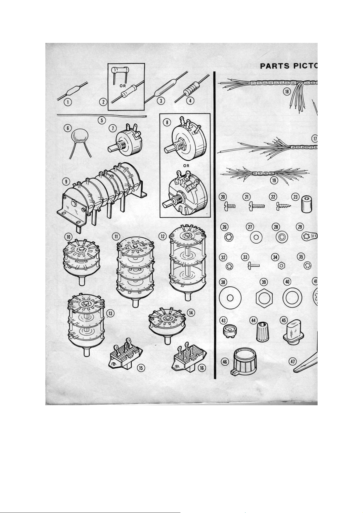
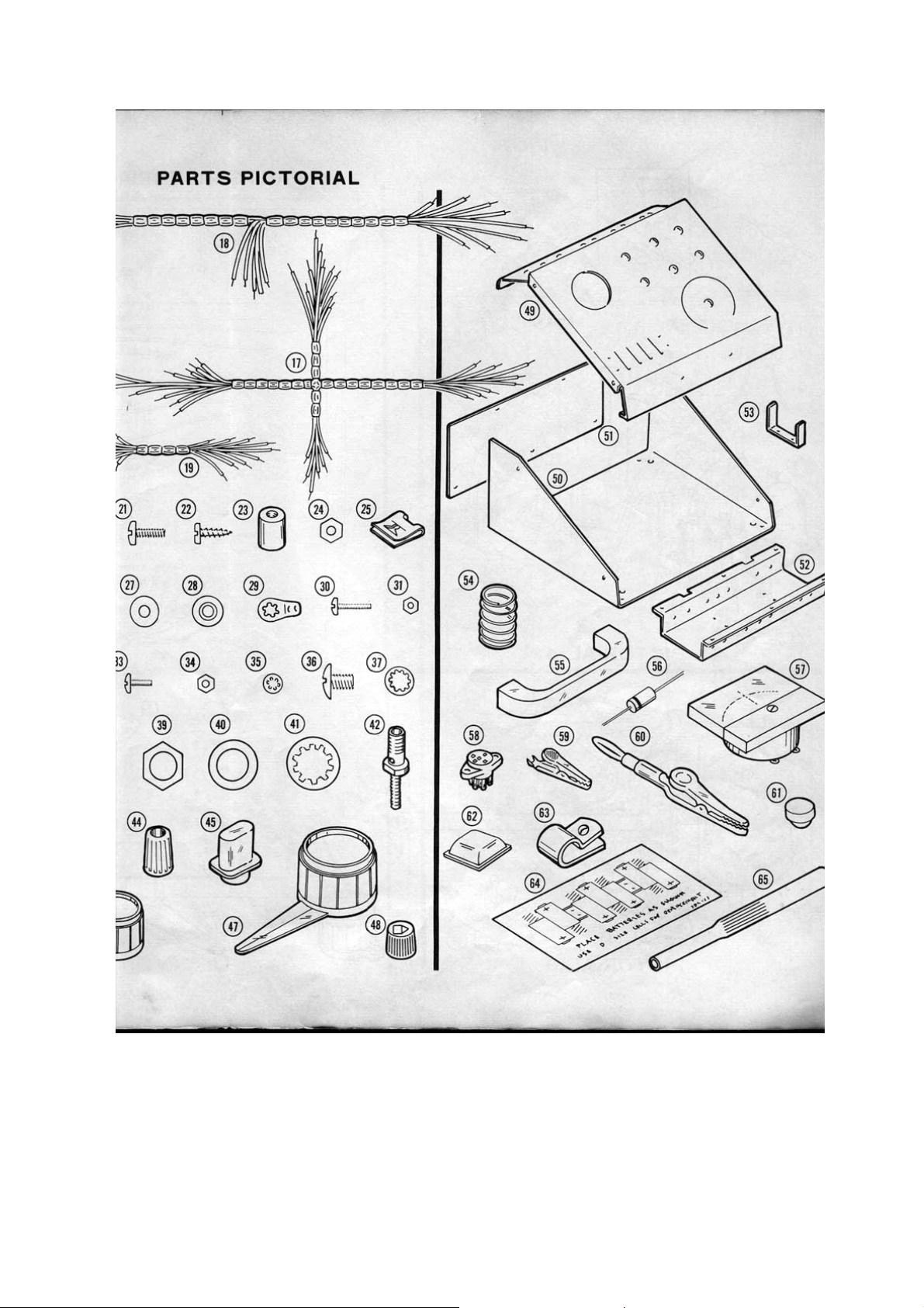
Parts List
Note: the numbers in parenthesis in the Parts List are keyed to the numbers on the
Parts Pictorial (Fold-out from Page 5).
To order replacement parts, refer to the "Replacement parts Price List" on Page 47 and
use the Parts Order Form furnished with this kit.
Note: Precision resistors may be marked in Ω, KΩ, or MΩ. (KΩ equals 1000Ω, MΩ
equals 1,000,000Ω).
Part No.
Resistors
Precision 1%, 0.5 watt.
(1) 2-148 1 0.09Ω
2-148 1 0.9Ω
2-229 1 2Ω
(2) 2-19 1 9Ω
2-230 2 18Ω
2-24 1 90Ω
Parts Per
Kit
Description
Page 3

Parts Per
Part No. Kit Description
2-231 2 180Ω
2-29 1 900Ω
2-232 1 1800Ω (1.8kΩ)
2-233 1 2020Ω (2.02kΩ)
2-35 1 9000Ω (9kΩ)
2-189 1 18KΩ
2-156 1 145KΩ
2-157 1 350KΩ
2-14 1 1MΩ
2-158 1 3.5MΩ
2-17 1 10MΩ
2 watt.
(3) 2-15-2 1 2Ω 1%
(4) 3-5-2 1 2.2Ω 10% (red-red-gold-silver)
Other Resistances.
(5) 340-12-1 1 0.01Ω resistance wire.
Capacitors
(6) 21-48 2 0.05 uf Disc.
Controls
(7) 11-75 1 20KΩ 2 Watt
(8) 11-79 1 100Ω 4 Watt
Switches
(9) 62-14 1 3-position 6 wafer 4 lever
(10) 63-440 1 3-position 2-wafer rotary
(11) 63-441 1 10-position 4-wafer rotary
(12) 63-442 1 6-position 3-wafer rotary
(13) 63-443 1 10-position 3-wafer rotary
(14) 63-444 1 6-position 1-wafer rotary
(15) 60-4 1 SPDT Slide
(16) 60-5 1 DPST slide
Wire Harnesses and Wire
(17) 134-138 1 Main wire harness
(18) 134-152 1 Battery pack wire harness
(19) 134-153 1 Small wire harness
344-6 1 Red wire
344-59 1 White wire
Hardware #6
(20) 250-56 10 6-32 x ¼" screw
(21) 250-89 24 6-32 x 3/8" screw
Page 4

Parts Per
Part No. Kit Description
(22) 250-8 7 #6 x 3/8" sheet metal screw
(23) 255-23 2 6-32 threaded spacer
(24) 252-3 40 6-32 nut
(25) 252-22 8 6-2 speednut
(26) 254-1 15 #6 lockwasher
(27) 253-1 7 #6 fibre flat washer
(28) 253-2 14 #6 fibre shoulder washer
(29) 259-1 23 #6 solder lug
Other Hardware
(30) 250-175 2 2-56 x 3/8" screw
(31) 252-51 2 2-56 nut
(32) 254-7 2 #3 lockwasher
4-40 Hardware
(33) 250-52 4 4-40 x ¼" screw
(34) 252-2 4 4-40 nut
(35) 254-9 4 #4 lockwasher
(36) 250-107 2 10-24 x ¼" screw
(37) 254-3 2 #10 lockwasher
(38) 253-6 7 #10 flat fibre washer
Control Hardware
(39) 252-7 7 Control nut
(40) 253-10 7 Control flat washer
(41) 254-4 7 Control lockwasher
Binding Post and Knob Parts
(42) 427-3 9 Binding Post Base
(43) 75-17 18 Binding Post base insulator
(44) 100-16-2 6 Black Binding Post Cap
100-16-18 3 Red Binding Post Cap
(45) 462-97 4 Lever Switch Knob
(46) 462-245 6 Small Round Knob
(47) 462-253 1 Large Pointer Knob
(48) 455-50 7 Knob bushing
Metal Parts
(49) 203-740-1 1 Panel
(50) 90-502-2 1 Cabinet Shell
(51) 205-307-2 1 Rear Cover
(52) 214-14 1 Battery Housing
(53) 204-413 2 Battery Spacing bracket
(54) 258-43 7 Battery Contact Spring
(55) 211-14 1 Handle
Miscellaneous
(56) 56-10 2 Silicon Diode
Page 5

Parts Per
Part No. Kit Description
(57) 407-122 1 Meter (10-0-10 uA)
(58) 434-116 1 Transistor Socket
(59) 260-16 1 Alligator clip
(60) 438-14 2 Alligator clip with adaptor
(61) 261-4 4 Rubber Foot
(62) 261-28 4 Plastic Foot
(63) 207-18 2 3/8" cable clamp
(64) 390-114 1 Battery label
391-34 1 Blue & white identification label
(65) 490-5 1 Nut starter
597-308 1 Kit Builders Guide
597-260 1 Parts Order Form
1 Manual (See front cover for part
number.
Solder.
Note: Seven D-cell flashlight batteries (not furnished) will be required for operation of
the completed Transistor Tester. You may want to purchase these batteries now to
have them ready when you finish assembling the kit.
Step-By-Step Assembly
Before you start to assemble the Transistor Tester, read the Kit Builders Guide for
complete information on wiring, soldering, and step-by-step assembly procedures.
As you perform a step in the Step-by-step assembly, first read the step completely
through. Then perform the operation as directed. Position each part as wire as shown
on the pictorial that accompanies the series of steps. The details provide specific
information for individual steps.
Switch Pre-wiring
The assembly of this kit will begin with the pre-wiring of the switches. Before you begin
to pre-wire a switch, compare its physical construction with its pictorial so you can
identify the contacts and lug positions. Note that each contact position has a number,
even if it does not have a lug.
To hold the switch firmly while you connect the wires, you may find it convenient to
temporarily mount the switch in one of the 3/8" holes in the control panel. Place a
towel or soft cloth on your work surface to avoid scratches, and mount the control on
the inside of the panel.
Polarity Switch (#63-440)
Note: When wiring some of the parts in this kit, you will be instructed to prepare
lengths of wire ahead of time, as in the following steps. To prepare a wire, cut it to the
indicated length and remove ¼" of insulation from each end. The wires are listed in the
order in which they will be used.
Page 6
Page 7
Page 8
Page 9
Page 10
( ) Prepare the following lengths of wire:
Wire Colour Length
Red 3-¼"
White 4–¼"
White 4–¼"
White 6–¼"
White 8–¼"
* Red 3-½"
* Red 2-¼"
* Red 2-¾"
* Remove ¼" of insulation from one end and ¾" of insulation from the other end of
these three red wires.
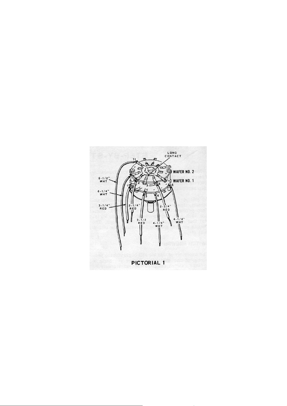
Refer to Pictorial 1 for the following steps.
( ) Locate the 3-position 2-wafer Polarity switch (#63-440) and compare its wafer
and lug positions with those numbered in the Pictorial. Note that the long contact
on wafer 2 is identified as lug 3.
Note: Only the switch wafer and lug number will be called out in the following steps.
As you connect a wire to a lug, pass the end of the wire through the lug. Then crimp
the end of the wire around the lug to hold it in place until you are instructed to solder
the connection, be sure to solder the connection, be sure to solder both lugs and the
wire.
Connect one end of each of the prepared wires to the 3-position 2-wafer Polarity switch
as follows.
Page 11
( ) 3-¼" red to wafer 1 lug 1 (S-1).
( ) 4-¼" white to wafer 1 lug 4 (S-1).
( ) 4-¼" white to wafer 1 lug 6 (S-1).
( ) 6-¼" white to wafer 2 lug 1 (S-1).
( ) 8-½" white to wafer 2 lug 11 (S-1).
( ) 3-½" red, short end to wafer 1 lug 3 (S-1).
( ) 2-¼" red, short end to wafer 2 lug 2 (S-1).
( ) 2-¾" red, short end to wafer 2 lug 4 (S-1).
This completes the pre-wiring of the Polarity switch. Set the switch aside until it is
called for later.
Collector Voltage Switch (#63-441)
( ) Prepare the following lengths of white wire:
1-¼", 1-¾", 2", 2-½", 2-¾"
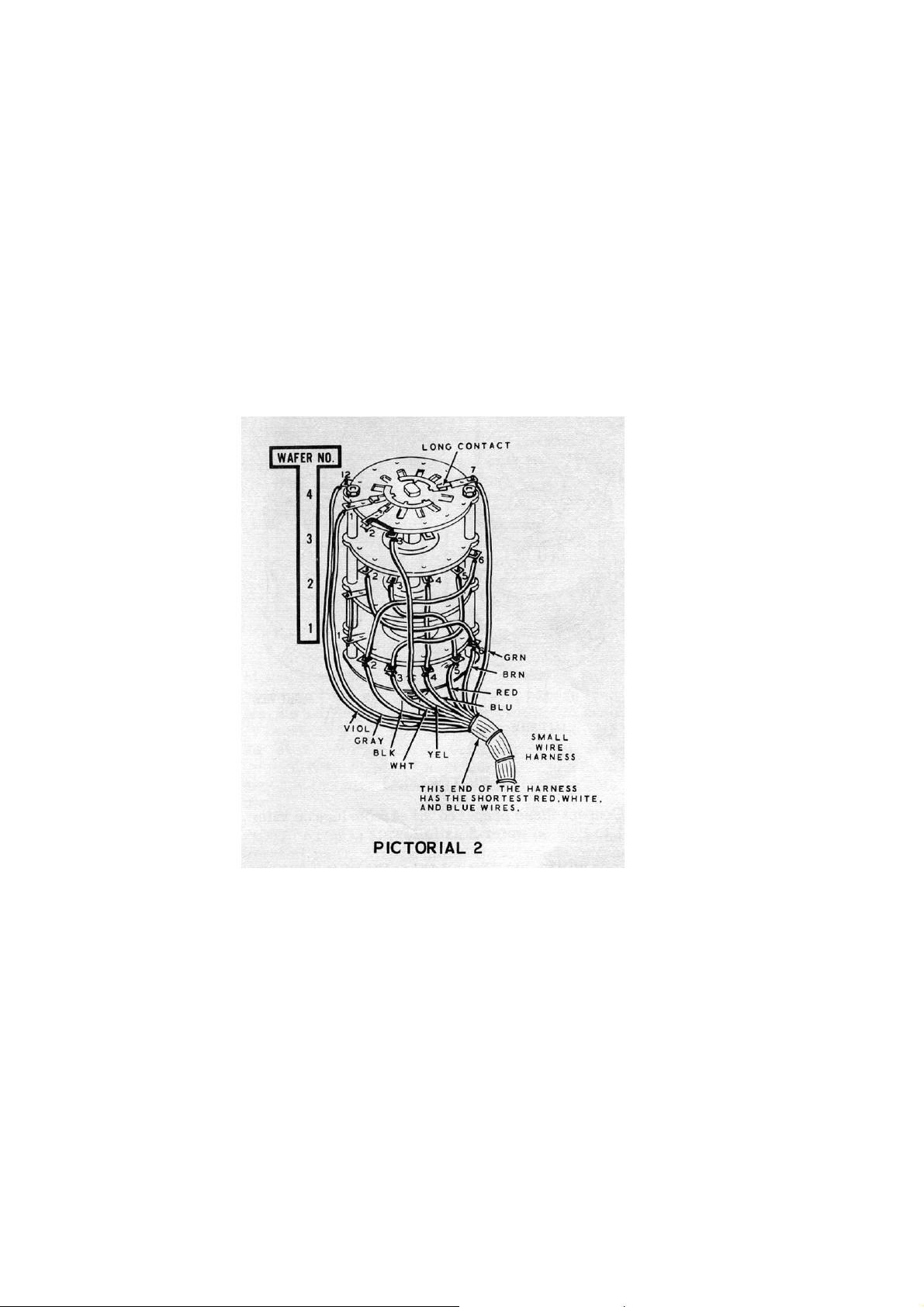
Refer to Pictorial 2 for the following steps:
( ) Locate the 10 position 4 wafer Collector voltage switch (#63-441). Compare the
lug positions with those shown in Pictorial 2. Note that the long contact on wafer
4 is lug 7.
Connect the prepared wires from wafer 3 to wafer 1 in the following steps:
Wire From Wafer 3 To Wafer 1
( ) 1-¼" Lug 4 (NS) Lug 4 (NS)
Page 12

( ) 1-¾" Lug 3 (NS) Lug 5 (NS)
( ) 2-¾" Lug 2 (NS) Lug 6 (NS)
( ) 2" Lug 5 (NS) Lug 3 (NS)
( ) 2-½" Lug 6 (NS) Lug 2 (NS)
( ) Strip the insulation from a 1-½" length of white wire. Then cut this bare wire into
two ¾" lengths.
Connect the two ¾" bare wires as follows:
( ) From wafer 1 lug 1 (NS) to wafer 2 lug 1 (S-1).
( ) From wafer 4 lug 3 (NS) to wafer 4 lug 2 (S-1).
( ) Locate the small wire harness (#134-153) and note the end that has the shortest
red, white and blue wires.
Wires from the end of the wire harness just identified will be connected to the
Collector Voltage switch in the following steps. Wires at the other end of the
harness will be connected later.
( ) Bend the four longest wires back away from the five short wires. This will help
avoid accidentally burning any wires while soldering.
Connect the following harness wires to wafer 1 of the switch.
( ) Black to lug 2 (S-2).
( ) White to lug 3 (S-2).
( ) Blue to lug 4 (S-2).
( ) Red to lug 5 (S-2).
( ) Brown to lug 6 (S-2).
Connect the following harness wires to wafer 4 of the switch.
( ) Violet to lug 12 (S-1).
( ) Grey to lug 1 (S-1).
( ) Yellow to lug 3 (S-2).
( ) Green to lug 7 (S-1).
( ) Carefully examine the lugs of the switch. All lugs on wafers 1, 2 and 4 that have
wires attached should have been soldered, except lug 1 on wafer 1. Lugs 2, 3,
4, 5 and 6 of wafer 3 have wires that are not soldered.
This completes the pre-wiring of the Collector Voltage switch. Set the switch aside until
it is called for later.
Page 13
Leak Voltage Switch (#63-443)
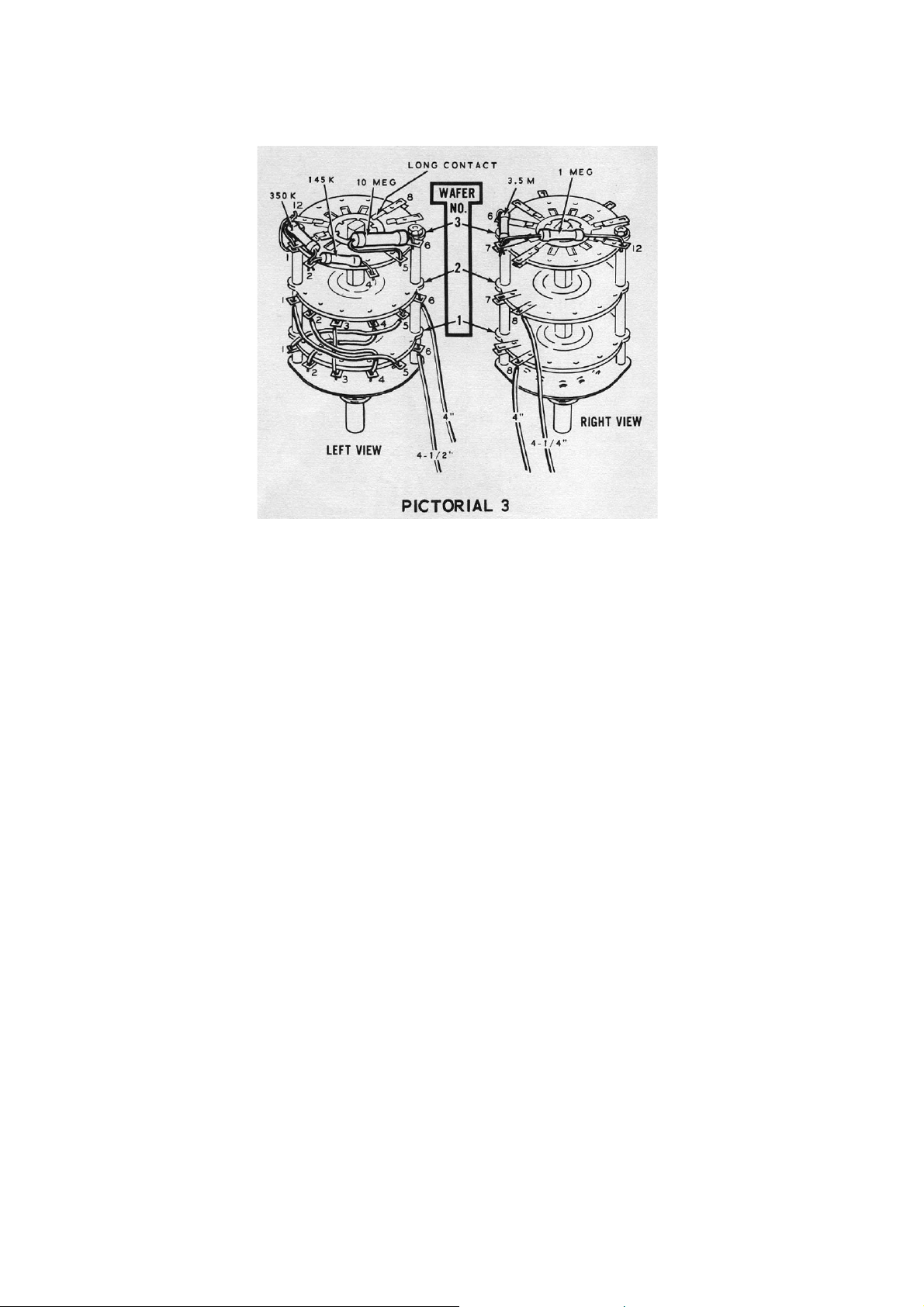
Refer to Pictorial 3 for the following steps.
( ) Locate the 10-position 3-wafer Leak Voltage switch (#63-443). Compare the
switch with Pictorial 3 so that you can identify the lug numbers. Notice that lug 8
is the long contact on wafer 3.
Note: When you connect a precision resistor, as in the following steps, do not handle
the resistor body with pliers or other tools. Preshape the resistor leads so its body can
be positioned as show in the Pictorial; then cut of the excess lead lengths after the
resistor is installed.
The following 1% precision resistors will be connected to the lugs on wafer 3 of the
Leak Voltage switch. Position each resistor as shown in Pictorial 3.
( ) 145KΩ from lug 4 (NS) to lug 2 (NS)
( ) 10 MΩ from lug 5 (S-1) to lug 6 (NS)
( ) 3.5 MΩ from lug 6 (NS) to lug 7 (NS).
( ) 1 MΩ from lug 7 (NS) to lug 12 (NS)
Note: Where a wire passes through one lug then goes to another point, as in the
following step, it will count as two wires in the soldering instruction (S-2) one entering
and one leaving.
( ) Pass one lead of the 350KΩ precision resistor through lug 1 (NS) to lug 12 (NS).
Shape the lead away from the switch spacer. Then connect the other lead of this
resistor to lug 2 (NS). Now solder lug 1 (NS).
( ) Prepare the following lengths of wire.
7/8 ", 1-¾", 2 x 1-½", 2-½"
Page 14

Connect these prepared wires from lugs on wafer 1 to lugs on wafer 2 as follows.
( ) 1-¾" 1 (NS) 5 (S-1)
( ) 1-½" 2 (NS) 4 (S-1)
( ) 1-½" 4 (NS) 2 (S-1)
( ) 2-½" 5 (NS) 1 (S-1)
( ) 7/8" 3 (NS) 3 (S-1)
( ) Prepare the following lengths of wire:
2 x 4", and 2 x 4-½"
Connect only one end of each of these prepared wires to lugs on the switch as follows.
( ) 4-½" to wafer 1 lug 6 (S-1).
( ) 4" to wafer 2 lug 6 (S-1).
( ) 4" to wafer 1 lug 8 (S-1).
( ) 4-¼" to wafer 2 lug 8 (S-1).
(There appears to be a small error here, no 4-¼" length was prepared)
This completes the wiring of the Leak Voltage switch. Set the switch aside until it is
called for later.
Wire From Wafer 1 Lug To Wafer 2 lug
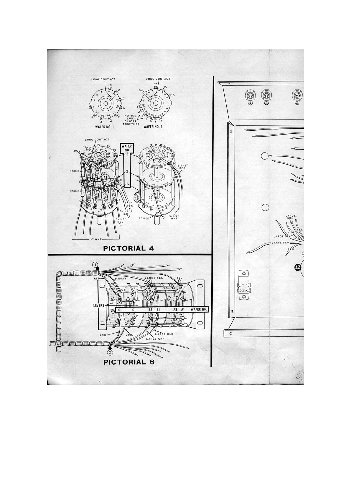
Collector Current Switch (#63-442)
Refer to Pictorial 4 (fold-out from page 6) for the following steps.
( ) Locate the 6-position 3-wafer Collector Current switch (#63-442) and compare its
contacts and lugs with those shown in Pictorial 4. Notice that some lugs on
wafers 2 and 3 are closer together than the lugs on wafer 1. The long contact on
wafer 3 is lug 20.
Caution: Use extra care in making connections to the closely spaced lugs on the
switch. Bend wires over the end of the lug. Trim excess lead lengths close to the lug.
Be careful not to bend or break a lug. Where there is a front and rear lug at a position
on a wafer, pass the wire through both lugs. Then be sure to solder both lugs and the
wire when you are instructed to solder.
Note: The 1% precision resistors may be marked in Ω, KΩ, or MΩ (KΩ = 1000Ω, MΩ
= 1,000,000Ω). For example: 1800Ω = 1.8KΩ, 2020Ω = 2.02KΩ, Examine each
resistor carefully to be sure you install the correct value each time. As you install a
resistor on the switch, pre-shape the leads so the resistor body can be positioned as
shown in Pictorial 4.
Read each step completely through first; then perform the operation described in the
step. Connect both leads of each resistor before you solder either lead.
In the following steps, you will connect 1% precision resistors to lugs on the wafers of
the Collector Current switch.
Page 15

( ) Connect the 18KΩ resistor from lug 1 (NS) to lug 11 (NS) on wafer 2. Position
the resistor away from the movable parts of the switch.
( ) Pass one end of the 1800Ω (1.8KΩ) through lug 2 on wafer 3 (S-2) to lug 3 on
wafer 2 (NS). Connect the other end of this resistor to lug 1 on wafer 2 (S-2).
( ) Pass one lead of a 180Ω resistor through lug 4 on wafer 3 (S-2) to lug 5 on wafer
2 (NS). Connect the other lead to lug 3 on wafer 2 (S-2).
( ) Pass one lead of an 18Ω resistor through lug 6 on wafer 3 (S-2) to lug 7 on wafer
2 (NS). Connect the other lead to lug 5 on wafer 2 (S-2).
( ) Connect the 2Ω 0.5 watt precision resistor from lug 7 on wafer 2 (NS) to lug 9 on
wafer 2 (NS).
( ) Connect the 2Ω 2 watt precision resistor from lug 11 on wafer 2 (NS) to lug 7 on
wafer 3 (NS).
( ) Connect the remaining 18Ω precision resistor from lug 7 (S-2) to lug 5 (NS) on
wafer 3.
( ) Connect the remaining 180Ω precision resistor from lug 5 (S-2) to lug 3 (NS) on
wafer 3.
( ) Connect the 2020Ω (2.02 KΩ) resistor from lug 3 (S-2) to lug 1 (S-1) on wafer 3.
( ) Connect the 0.09Ω resistor from lug 6 (NS) to lug 7 (NS) on wafer 1.
( ) Pass one lead of the 0.9Ω resistor through lug 10 on wafer 2 (S-2) to lug 6 on
wafer 1 (NS). Connect the other lead to lug 5 on wafer 1 (NS).
( ) Pass one lead of the 9Ω resistor through lug 8 on wafer 2 (S-2) to lug 5 on wafer
1 (NS). Connect the other lead to lug 4 on wafer 1 (NS).
( ) Pass one lead of the 90Ω resistor through lug 6 on wafer 2 (S-2) to lug 4 on
wafer 1 (NS). Connect the other lead to lug 3 on wafer 1 (NS).
( ) Connect the 900Ω resistor from lug 4 on wafer 2 (NS) to lug 2 on wafer 1 (NS).
( ) Remove the insulation from a 1-½" white wire. Then connect this wire from lug 4
on wafer 2 (S-2) to lug 3 on wafer 1 (NS).
( ) Pass one lead of the 9000Ω (9KΩ) resistor through lug 2 on wafer 2 (S-2) to lug
2 on wafer 1 (NS). Connect the other lead to lug 1 on wafer 1 (NS).
( ) Remove the insulation from a 2-¾" length of red wire. Then cut this bare wire
into two 1-3/8" lengths.
In the next two steps, you will connect the heavy bare wires you have just prepared.
( ) 1-3/8" bare wire from lug 7 on wafer 1 (S-2) to lug 12 on wafer 2 (S-1).
( ) 1-3/8" bare wire from lug 8 on wafer 1 (S-1) to lug 14 on wafer 2 (NS).
Page 16

( ) Remove ¼" of insulation from each end of a 2" red wire. Then, connect one end
of this wire to lug 16 on wager 2 (S-1). The other end will be connected later.
( ) Prepare the following lengths of red wire.
3", 2 x 3-½", 5-½"
Connect one end of each of these prepared wires in the following steps.
( ) 3-½" to lug 6 on wafer 1 (S-3).
( ) 5-½" to lug 9 on wafer 2 (S-2).
( ) 3" to lug 11 on wafer 2 (S-3).
( ) 3-½" to lug 20 on wafer 3 (NS).
( ) Prepare a 5-½" white wire, then connect one end of this wire to lug 20 on wafer 3
(S-2).
( ) Prepare five 3" lengths of white wire.
In the following steps you will connect one end of each of these prepared 3" wires to
lugs on wafer 1.
( ) Lug 1 (NS).
( ) Lug 2 (S-3).
( ) Lug 3 (S-3).
( ) Lug 4 (S-3).
( ) Lug 5 (S-3).
This completes the pre-wiring of the Collector Current Switch. Set the switch aside
until it is called for later.
Lever Switch (#62-14)
Refer to Pictorial 5 for the following steps.
( ) Locate the 3-position 6-wafer 4-lever switch (#62-14) and compare its sections,
wafers, and lugs with those shown in Pictorial 5.
Note: the lever switch contains four separate switch sections, marked A, B, C, and D in
Pictorial 5. Sections A and B each have two wafers, while sections C and D each have
one wafer. To identify the wafers and lugs on the lever switch, a letter-number
combination will be used as follows: The letter will identify the section and the first
number will identify the wafer in that section. The number that follows the dash will
indicate the lug. For example A2-11 would refer to section A, wafer 2, lug 11.
( ) Cut the following lengths of red wire (10), then remove the insulation from each
of them. (These will be the bare wires used in the steps that follow.)
Page 17

2 x ¾", 1", 1-¼", 1-1/8", 2 x 1-½", 2-3/8", 2 x 2-¾",
Note: You will connect the bare wires to lugs on the lever switch in the following steps.
Pass the wire through the lugs in the order given; then solder only the lugs indicated.
Where two lugs appear at a position on a wafer, and you are instructed to solder, be
sure to solder both of the lugs and the wire. Be sure none of the bare wires touch any
metal parts.
Position the lever switch as shown in the upper part of Pictorial 5. Then connect the
prepared bare wires as follows:
( ) 1" from B2-6 (S-1) to A2-6 (S-1).
( ) 2-¾" through lug 5 on all wafers. Solder all but D1-5 (NS).
( ) ¾" from D1-4 (S-1) to C1-4 (NS).
( ) 1-½" through B2-2 (S-1), B1-2 (S2), A2-2 (S-2), A1-2 (S-1).
( ) 1-½" through B2-1 (NS), B1-1 (S-2), A2-1 (S-2), A1-1 (S-1).
( ) Connect the 2.2Ω 2 watt (red-red-gold-silver) resistor from C1-1 (S-1) to B2-1 (S-
2). Position the resistor as shown.
( ) Remove ¼" of insulation from each end of a 2" length of red wire. Then connect
this wire from C1-4 (S-2) to B2-4 (NS). Shape and position the wire as shown.
Page 18
( ) Remove ¼" of insulation from each end of a 2-½" length of red wire. Then
connect this wire from B2-4 (S-2) to A1-4 (S-1).
( ) Remove ¼" of insulation from each end of a 2-½" length of white wire. Then
connect one end of this wire to D1-2 (NS). The other end will be connected later.
Position the switch as shown in the lower part of Pictorial 5. Then connect the rest of
the prepared bare wires as follows.
( ) 1-1/8" from B2-7 (S-1) to A2-7 (NS).
( ) ¾" from D1-7 (S-1) to C1-7 (NS).
( ) 1-¼" from B1-9 (S-1) to A1-9 (NS).
( ) 2-¾" through lug 10 on al wafers. Solder all of the lugs.
( ) 2-3/8" through lug 11 on all wafers. Solder all but A2-11 (NS).
( ) Connect a 2-7/8" red wire from A1-8 (S-1) to D1-8 (NS).
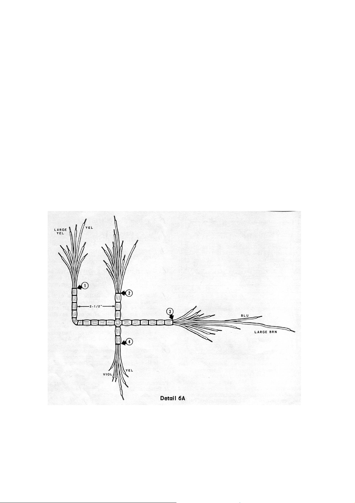
Refer to Pictorial 6 (fold-out from Page 6) for the following steps.
( ) Locate the main wire harness (#134-138). Form the harness as shown in Detail
6A. Note that the breakout #1 has a large yellow and small yellow wire, and
breakout #3 has a long large brown wire.
Page 19

( ) Position the wire harness and the lever switch as shown in Pictorial 6.
Note: In the following steps, you will connect the harness wires to the lever switch.
Some of the switch lugs were left unsoldered to accept the small wires from the
harness. When you connect the large wires, form a hook in the end of the wire; then
wrap the hook around the bare wire near the specified lug and solder the connection.
Small wires are called out by their colors, while large wires are labelled "large". For
example, "yellow" and "large yellow."
Connect the wires from breakout #2 as follows:
( ) Green to D1-2 (S-2).
( ) Violet to C1-2 (S-1).
( ) Large green to B2-2 (S-1).
( ) Large black to B1-1 (S-1).
Connect the wires from breakout #1 as follows:
( ) Gray to D1-5 (S-2).
( ) Red to D1-4 (S-2). Note that this lug was soldered previously. Heat the
connection; then insert the red wire and resolder.
( ) Large yellow to B2-6 (S-1).
( ) Yellow to A1-6 (S-1).
The remainder of the harness wires will be connected after the lever switch is installed.
Carefully examine the connections on the lever side of the switch. Every lug should
be connected and soldered. Be sure that no bare wires touch any metal parts. Set the
lever switch aside temporarily.
Control Panel Parts and Initial Wiring.
Most of the parts in the Transistor Tester will be mounted and wired on the control
panel. The operations in this part of the manual are divided into three sections as
follows:
1. Initial parts mounting.
2. Switch mounting and wiring
3. Other parts mounting and wiring.
Initial Parts Mounting.
Refer to Pictorial & (fold-out from page 15) for the following steps.
( ) Locate the control panel and position it as shown. Place a towel or soft cloth on
your work surface to avoid scratching the panel.
Page 20

Note: the Heath Company has provided a plastic nut starter with this kit. Use this nut
starter to hold and start 2-56, 4-40, and 6-32 nuts on screws. Refer to page 3 of the Kit
Builders Guide for further information.
( ) Install a binding post base at AA. Use a
binding post base, two binding post
insulators, a #6 lockwasher, a #6 solder
lug, and two 6-32 nuts as shown in Detail
7A.
( ) In a like manner, install binding posts at
AB, AC, AD, AE, AF, AG, AH, and AJ.
( ) Install red binding post caps on the binding
posts at AA, AC, and AE. Each of these
binding posts is marked ( + ) on the top of
the panel. Turn each cap all the way onto
its base.
( ) Install black binding post caps on the
remaining six binding posts. Turn each cap
all the way onto its base.
Note: If you wish to keep the binding posts from
falling off when they are loosened, perform the
following step at each of the binding posts that
were just installed.
( ) Insert the tip of a ¼" shaft Philips screwdriver into the open end of the binding
post cap. Then tap the handle of the screwdriver sharply with a small hammer or
tool. Support the binding post so the hammer blow does not crack this insulator
or bend the panel.
( ) Refer to detail 7B and install the SPDT
slide switch (#604) at AK. Use two 6-32 x
¼" screws and position the switch as show
in Pictorial 7.
( ) In the same manner, install the DPST slide
switch (#60-5) at AL with two 6-32 x ¼"
screws.
( ) Install the handle on the front apron of the
control panel. Use two 10-24 x ¼" screws
and #10 lockwashers.
( ) Refer to Detail 7C and install the transistor
socket at AN. Use 2-56 x 3/8" screws, #3
lockwashers, and 2-56 nuts as shown. Be
sure to position the socket so lug 1 is
toward the edge of the panel.
( ) This completes the initial control panel
Page 21

parts mounting. Other parts will be mounted and wired in the following sections.
Switch Mounting and Wiring.
he pre-wired switches will be mounted and wired in this section. Handle the switches
T
carefully to avoid damaging the wafers or contacts.
osition the wires as shown in the Pictorials, and be sure you do not pinch any wires
P
under mounting hardware
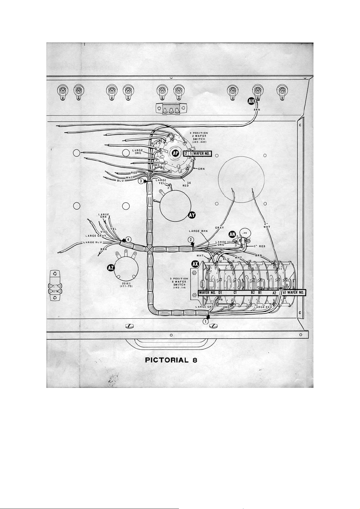
efer to Pictorial 8 (fold-out from page 6) for the following steps.
R
) Mount the pre-wired lever switch at AX as shown in Detail 8A. Use 4-40 x ¼"
(
screws, #4 lockwashers, and 4-40 nuts. First mount the switch loosely; then turn
the panel over and be sure the switch levers are centred in their slots. Finally,
tighten the hardware.
) Connect the white wire that comes from lever switch D1-2 to lug 2 of transistor
(
socket AN (NS).
) Connect a 3" red wire from lever switch D1-12 (NS) to lug 1 of transistor socket
(
AN (NS)
Page 22

( ) Connect one lead of a 0.05 uF disc capacitor through lug 5 (S-2) to lug 2 (S-2) of
transistor socket AN. Connect the other lead of this capacitor to lug 1 (S-2) of
the same socket.
( ) Prepare a 6" white wire and connect one end to lever switch A2-11 (S-2). The
other end will be connected later.
onnect the wires from breakout #2 of the wire harness as follows:
C
) Large brown to D1-12 (S-2).
(
) Blue to C1-12 (S-1).
(
) White to B2-12 (S-1).
(
) Brown to A2-12 (S-1).
(
) Large orange to lug 3 of transistor socket AN (S-1).
(
he grey wire from breakout #2 will be connected later.
T
onnect the wires from breakout #1 to the lever switch as follows:
C
) Orange to C1-7 (S-2).
(
) Large Grey to D1-8 (S-2).
(
Page 23

( ) Large red to A2-7 (S-2).
) Larger blue to A1-9 (S-2).
(
ll wires from breakouts #1 and #2 should now be connected and soldered except one
A
grey wire from breakout #2. This wire will be connected later.
res from breakout #3 of the main wire harness will be connected to the Polarity
Wi
switch, before the switch is mounted, in the following steps.
) Locate the pre-wired 3-position 2-wafer Polarity switch (#63-440). Be sure to
(
correctly identify the wafers and lugs. Wafer 1 is nearest the knob end of the
shaft and lug 3 is the long contact on wafer 2. See detail 8B.
onnect the wires from breakout #3 to the lugs on wafer
C
1 as follows:
) Large black to lug 2 (S-1).
(
) Orange to lug 5 (S-1).
(
) Large red to lug 8 (S-1).
(
) Green to lug 9 (NS).
(
) Connect the large orange wire to lug 3 on wafer 2 (NS).
(
Page 24

( ) Refer to detail 8C and mount the Polarity switch at
AP on the front panel. Use a control lockwasher,
control flat washer, and a control nut. Position the
switch and its wires as shown in Pictorial 8.
) Install the 100Ω control (#11-79) at AY as shown
(
in Detail 8D. Use a control lockwasher, a control
flat washer, and a control nut. Position the control
as shown in pictorial 8.
) In a like manner, install the 20KΩ control (#11-75)
(
at AZ.
) Connect the large yellow wire from wire harness
(
breakout #3 to lug 3 of control AY (S-1).
) Connect the long brown wire from breakout #3 to
(
the solder lug at AH (NS). Route this wire along
the bend in the panel as shown in the Pictorial.
efer to Pictorial 9 (fold-out from page 16) for the
R
following steps.
) Mount the pre-wired 10-position 4-wafer Collector
(
voltage switch (#63-441) at AR. Use a control
lockwasher, a control flat washer, and a control nut
as shown in detail 9A. Position the switch and its
wires as shown in Pictorial. Be sure you do not
pinch any wires under the mounting hardware.
) Note: Throughout the remainder of the step-by-
(
step assembly instructions, switches will be
identified by a letter number combination. For
example, the term AP2-11 would refer to switch
AP, wafer 2, lug 11.
) Connect the white wire from AP2-11 to solder
(
lug AA (NS).
) Connect the white wire from AP2-1 to solder lug
(
AB (NS).
) Connect the red wire from AP1-1 to AR1-1 (S-2).
(
) Connect the red wire that comes from AP1-3
(
through AR2-12 (S-2) to AR3-12 (S-1)
) Connect the red wire that comes from AP2-4
(
through AR1-11 (NS) to AR2-11 (S-1).
) Prepare the following lengths of wire.
(
2-¼" red, 2-½" red, 3" red, 5" red, 5" white, 8"
white, 8-½" red
Page 25

( ) red wire from AR1-11 (S-3) to solder lug AD (S-1).
( ) Connect the red wire that comes from AP2-2 through AR2-10 (NS)
( ) nect a 3" red wire from AR2-10 (S-3) to solder lug AC (S-1).
( ) Connect a 2-½" red wire from AP1-10 (S-1) to lug 2 of switch AK
( ) Connect a 5" red wire from AP1-9 (NS) to solder lug AG (NSD).
( ) Connect a one end of a 5" white wire to AP1-9 (S-3). The o
( ) red wire from AP2-3 (NS) to solder lug AJ (S-1).
( ) Connect one end of an 8" white wire to AP2-3 (S-3). The oth
( ) F disc capacitor from solder lug AG (S-2) to solder lug AH (S-2).
( ) Remove the insulation from a 1" red wire. Then connect this bare wire from
Refer
( ) Mount the pre-wired 10-position 3-wa
Connect the free ends of the wires from the switches as follows:
( ) White from AS1-8 to solder lug AA (S-2).
Connect a 2-¼"
to AR3-10 (S-
1).
Con
(S-1).
ther end will be
connected later.
Connect an 8-½"
er end will be
connected later.
Connect a 0.05 u
solder lug AE (S-1) to lug 1 of switch AK (S-1).
to Pictorial 10 for the following steps.
fer Leak Voltage switch (#63-443) on the
control panel at AS. Use a control lockwasher, control flat washer, and a control
nut. Position the switch as shown in Pictorial 10. Be sure you do not pinch any
wires under the mounting hardware.
Page 26

( ) White from AS2-8 to solder lug AB (S2).
( )
(
(
(
In
the ven length; then remove ¼" of ins
w
( ) Connect a 3" whiter wire from AR1-7 (S-2) to AP2-7 (NS).
( )
(
T
the llowing steps. Connect the ends of these wires to lugs on wafer
fo
( ) Black to AS1-5 (S-2).
(
(
(
(
C
White from AP1-6 to AS1-7 (S-1).
) White from AP1-4 to AS2-7 (S-1).
) White from AS2-6 to AR1-7 (NS).
) White from AS1-6 to AR3-7 (NS).
the next three steps, the length and colour of each wire is called out. Cut the wire to
gi ulation from each end before connecting the
ire.
Connect a 2-¼" white wire from AR3-7 (S-2) to AP2-5 (NS).
) Connect a 5" red wire from solder lug AF (S-1) to AP1-7 (NS).
he wires from the small wire harness that comes from switch AR will be connected in
fo 1 of switch AS as
llows.
) White to AS1-4 (S-2).
) Blue to AS1-3 (S-2).
) Red to AS1-2 (S-2).
) Brown to AS1 (S-2).
onnect the following small harness wires to wafer 3 of switch AS:
Page 27

( ) Yellow to AS3-7 (S-3).
) Grey to AS3-6 (S-3).
(
) Green to AS3-2 (S-3).
(
) Violet to AS3-12 (S-3).
(
) Position the wires from the small wire harness as shown in Pictorial 10.
(
) Connect the white wire that comes from AP2-3 to AS3-4 (S-2).
(
) Carefully examine the lugs on switch AS. Every lug except lug 8 (long contact)
(
on wafer 3 should have been connected and soldered.
Other Parts Mounting and Wirin
g.
Refer to Pictorial 11 for the following steps.
) Install the 6-position 1-wafer Base Current switch (#63-442) at AT. Use a control
(
a control nut. Position the switch as shown
( )
lockwasher, a control flatwasher, and
in the Pictorial.
In a like manner, install the pre-wired 6-position 3-wafer Collector Current switch
(#63-442) at A
hardware.
U. Be careful not to pinch any wires under the mounting
Page 28

In t following steps you will connect the wires that come from lugs on wafer 1 of
he
switch
(
( ) White from AU1-2 to AT-2 (S-1).
( ) White from AU1-3 to AT-3 (S-1).
( ) White from AU1-4 to AT-4 (S-1).
( ) White from AU1-5 to AT-5 (S-1).
( ) Red from AU1-6 to AT-6 (S-1).
( ) Remove an extra ¼" of insulation
(
( ) Connect the red wire that comes from AU2-16 to lug 1 of control AY (S-1).
( ) wire that comes from AU2-11 to lug 1 of control AZ (NS).
( ) Connect the white wire that comes from AU3-20 to lug 3 of control AZ (S-1)
( ) Connect the white wire that comes from AP1-9 to AU2-20 (S-1).
( ) Remove ½" of insulation from one end, and ¼" of insulation from the other end,
Refer to Pictorial 12 (fold-out from page 27 for the following steps.)
Conne
( ) Blue to AS3-8 (S-1).
( ) White to AR4-4 (S-1).
( ) Red to AU1-1 (S-3).
Connect the wires from b
fo
(
( ) La
( ) Violet to AU2-10 (S-3
AU to corresponding lugs on switch AT.
) White from AU1-1 to AT-1 (S-1).
from the end of the red wire coming from AU2-
9. Then pass this end of the wire through lug 2 (S-2) to lug 1 (S-1) of switch AL.
) Connect the red wire that comes from AU3-20 to lug 2 of control AY (S-1). Move
the harness and other wires aside and be careful not to burn any wires with your
soldering iron.
Connect the red
.
of a 4" red wire. Pass the ½" bare end through lug 4 (S-2) to lug 3 (S-1) of switch
AL. Then connect the other end of this wire to lug 1 of control AZ
ct the remaining wires from breakout #3 of the wire harness as follows:
reakout #4 as
llows:
) Yellow to AU1-9 (S-1.)
rge Green to AU2-14 (S-2).
). Note that
AU2-10 was already soldered.
Reheat the lug and connect th
Then resolder.)
e wire.
(S-2).
Page 29

Large grey to AT-8 (S-1). ( )
( ) Large blue to the wire betw
( ) Carefully unpack the meter from the box and remove the sh
between the meter terminals.
( ) nt the meter on the front of the panel. Use the
( ) e lead of a silicon
( )
( ) " white wire from AP2-10 (S-1) to lug 1 of the meter (NS).
( ) Connect a 6" white wire from AP2-9 (S-1) to lug 2 of the meter (S-4).
( ) Connect the grey wire from breakout #2 of the wire harness to lug 1 o
( ) the length of resistance wire (#340-12-1) and shape it as shown in detail
T ompletes the Control
w
AT, or AU or on controls AY or AZ.
Refer to Detail 12A and mou
lockwasher and nuts that are supplied with the meter. Be careful not to
overtighten the nuts or you might pull the screw studs from the meter case.
Note: Refer to Detail 12B in the following steps to identify the cathode en
e silicon diodes.
th
Connect the cathod
diode to lug 1 of the meter (NS).
Connect the other end to lug 2 (NS).
Connect the cathode end of the
remaining silicon diode to lug 2 of the
meter (NS). Connect the other end to
lug 1 (NS).
Connect a 5
(S-4).
Locate
12C. then connect one end of this wire to the bare wire near AU1-7 (S-1).
Connect the other end of the resistance wire to the bare wire near D1-10 (S-1).
Do not cut this wire.
his c Panel Parts Mounting and Wiring. Check to see that all
ire ends are connected. There should be no unsoldered connections on switches AS,
een lugs 1 and 2 of switch AL (S-1).
orting wire from
ds of
f the meter
Page 30

Tip and shake the Control Panel to dislodge any bits of solder or wire clippings that
may have fallen unnoticed into the wiring.
Set the control panel aside temporarily and proceed to the Battery Housing Assembly
and Wiring instructions that follow.
Battery Housing Assembly and Wiring.
Refer to Pictorial 13 for the following steps.
( ) Locate the battery housing and position it
as shown in this Pictorial.
( ) Mount a battery contact spring a 1. Use a
6-32 x 3/8" screw, a #10 flat fibre washer,
a #6 fibre shoulder washer, a #6 solder
lug, and a 6-32 nut. See Detail 13A
( ) In a like manner, install battery contact
springs at 3, 5, 7, 9, 11, 13.
( ) Refer to detail 13B and install a 6-32 x
3/8" screw, #6 fibre shoulder washer, #6
fibre flat washer, #6 solder lug, and 6-32
nut at 2.
( ) In a like manner install similar hardware at 4,6, 8, 10, 12 and 14.
( ) Install 6-32 threaded spacers at BA and BB. Use 6-32 x ¼" screws and #6
lockwashers as shown in detail 13C.
( ) Install a battery spacer bracket at BC as show in detail 13D. Use a 6-32 x ¼"
hardware in one mounting hole and 6-32 x 3/8" hardware with a 3/8" cable clamp
in the other mounting hole.
Page 31

( ) In a like manner, install the other
battery spacer bracket and cable clam
at BD.
( ) Install 6-32 speednuts at each of the
holes on the battery housing flange as
shown in Pictorial 13. Be sure that the
flat side of each speednut faces
upward.
Position the battery housing as shown in
Pictorial 14 for the following steps.
( ) Locate the battery pack wire harness
and pass the four wires of breakout #3
through both cable clamps as shown
in the pictorial.
( ) Prepare the following lengths of bare
wire. To prepare the bare wire, first
cut the indicated lengths of red wire.
Then remove all the insulation from
each length.
3 x 1-¾", and 2 x 2-¼"
Connect these bare wires to the solder lugs
on the battery pack as follows:
( ) 2-¼" from lug 2 (NS) to lug 3 (S-1).
( ) 1-¾" from lug 4 (S-1) to lug 5 (NS).
( ) 1-¾" from lug 8 (S-1) to lug 9 (NS).
( ) 1-¾" from lug 10 (NS) to lug 11 (S-1).
( ) 2-¼" from lug 12 (S-1) to lug 13 (NS).
Connect the wires from breakout #3 of the
battery pack harness to the lugs on the
battery housing as follows:
( ) Yellow to lug 1 (S-1).
( ) Red to lug 2 (S-2).
( ) Brown to lug 9 (S-2).
( ) Orange to lug 10 (S-2).
Connect the wires from breakout #2 of the bottom pack harness to the lugs on the
battery housing as follows:
( ) Black to lug 5 (S-2).
Page 32

( ) Violet to lug 6 (S-1).
( ) Green to lug 7 (S-1).
( ) Grey to lug 13 (S-2).
( ) Blue to lug 14 (S-1).
This completes the assembly and wiring of the battery housing. Proceed to the Final
Wiring instructions that follow.
Page 33

Final Wiring
In the final wiring of your Transistor Tester, the battery pack harness wires will be
connected to switches AP and AR. Since there are already several wires connected to
these switches, you must be very careful not to accidentally burn any wires with your
soldering iron. Move aside any wires that are close.
Prefer to pictorial 15 and connect the wires from the battery pack harness as follows:
( ) Connect the blue wire to lug 3 of switch AK (S-1).
( ) Green to AP1-7 (S-2).
( ) Yellow to AP2-7 (S-2).
( ) Violet to AP2-5 (S-2).
( ) Brown to AR3-2 (S-2).
( ) Red to AR3-3 (S-2).
( ) Orange to AR3-4 (S-2).
( ) Grey to AR3-6 (S-2).
( ) Black to AR3-5 (S-2).
( ) Locate the alligator clip (#260-16)
and connect one end of the 4" red
wire as shown in detail 15A.
Lay the alligator clip aside it will be
used later.
Refer to Pictorial 16 for the following
steps.
( ) Mount the battery housing to the top
edge of the control panel as shown
in the Pictorial. Use three 6-32 x
3/8" screws.
( ) Peel away the paper backing from
the battery placement label. Then
press the label firmly into place in
the battery housing as shown in
Pictorial 16.
This completes the final wiring of your
Transistor Tester. Tip and shake the
assembly to dislodge any bits of solder or
wire ends that may have fallen unnoticed
into the wiring.
Page 34

Carefully examine all connections to be sure that they are properly made and soldered.
Now proceed to the knob installation steps that follow.
Knob Installation
The knobs supplied with this kit use knob bushings that provide positive action without
the use of setscrews.
In the following steps, you will install a knob on each switch and control shaft as shown
in detail 17A. Perform these steps carefully, since it is difficult to remove a knob from a
bushing once it is fully inserted.
Refer to Pictorial 17 for the locations of the switch and control shafts.
( ) Place a knob bushing on each of the switch and control shafts; the spring tab on
the bushing should face outward.
( ) Turn each control and switch shaft to its full counter-clockwise position.
Page 35

( ) Press a knob firmly onto only the BIAS control bushing with the pointer at the 7
o'clock position.
( ) With the bushing installed on it, remove the BIAS knob. Then press the knob
bushing firmly into the knob with the handle of a screwdriver.
Page 36

Page 37

( ) Reinstall the BIAS knob.
Note: The Gain control knob will not be installed until after the adjustments have been
made in a later section.
( ) Install a knob lightly on each of the switch shafts with the pointer at the full
counter-clockwise position.
( ) Turn each knob clockwise to see if the pointer lines up with each switch marking.
( ) If the pointers line up properly, press the knobs firmly onto the bushings and then
remove the knobs with their bushings. Press the bushings firmly into the knobs
with a screwdriver handle, then reinstall the knobs. If a pointer does not line up
properly, perform the next three steps.
Note: It is not necessary to perform the next three steps if the pointer lines up properly
at each switch marking.
1. ( ) Turn the knob pointer to a mid-position marking on the panel.
2. ( ) Remove the knob from the bushing and turn it slightly to line up the pointer with
the mid position marking.
3. ( ) Press the knob slightly onto the knob bushing. Then turn the knob to each
switch position and recheck the pointer alignment. If more than a slight error is
noticed at either end position, repeat these three steps.
Page 38

( ) When the pointer lines up properly with the switch positions, remove the knob
and bushing together and press the bushing firmly into the knob with a
screwdriver handle. Then replace the knob on the shaft.
( ) Install the four lever knobs on the lever shafts A, B, C, and D.
Battery Installation.
Note: Before you install batteries in the Transistor Tester, be sure the Polarity switch
is in the Transit / Off position.
( ) Refer to Pictorial 18 and install seven D-cell batteries in the battery housing. As
you install each battery, press the negative ( - ) end firmly against the battery
contact spring. Then slip the positive ( + ) end into place against the positive
contact screw head.
Batteries can be replaced in the same manner should they become weak through
extended use. After the Transistor Tester is fully assembled, it will only be necessary
to remove the rear cover to expose the batteries.
Initial Tests and Adjustments
The tests you will perform in this section of the Manual will verify that the Transistor
Tester was properly assembled and wired. The adjustments will calibrate the Gain
control knob for accurate gain measurements. See Figure 1 (fold-out from page 28) for
location of these switches and controls.
If the Indicated results are not obtained in any of these tests, refer to the In Case of
Difficulty section on Page 41
Initial Tests.
( ) Set the Polarity switch in the Transit/Off position.
( ) Set all other rotary switches and controls at their full counter-clockwise positions.
Page 39

Polarity Switch
( ) Pick up and shake the Transistor Tester from side to side to make the meter
pointer swing both side of zero. The pointer movement should be well damped
(hard to swing from zero) when the Polarity switch is set at Off.
( ) Repeat the above step with the Polarity switch set at NPN, and then at PNP.
The meter should swing much more freely now.
( ) Set the polarity switch at PNP.
Collector Voltage and Leak Voltage Switches
Note: The meter scales are marked 15-0-15 and 50-0-50. Voltage will be read on one
of the two scales, as indicate by the position of the Collector Voltage or Leak Voltage
switch. In the first position (1.5) of either switch, voltage reads on the 15-0-15 scale by
moving the decimal point one place to the left. In the next two switch positions (3 and
4.5), the 50-0-50 scale is used with the decimal moved one place to the left. For the
next three switch positions, voltage is read directly on the 15 scale.
( ) Raise lever switch B to the Collector Voltage position. The meter pointer
should deflect to the right and indicate 1.5 volts, or slightly higher if fresh
batteries were installed.
( ) Change the Polarity switch to NPN and repeat the previous step. The pointer
should deflect to the left and indicate 1.5 volts.
( ) Turn the Collector Voltage switch to 3, 4, 5, 6, 7.5 and 9 repeating the
preceding two steps at each position. The meter should indicate the same
voltage as marked for each position of the switch.
( ) Repeat the preceding three steps, using the Leak Voltage switch and raising
lever switch C to the Leak Voltage position.
Note: The meter will not deflect when lever switches B or C are raised if the
corresponding Collector Voltage or Leak Voltage switch is in any Ext position during
these tests.
Bias Control
( ) Temporarily connect a wire between the Emitter and Base binding posts.
( ) Set the switches and controls as follows:
Polarity Switch to PNP
Collector Current switch to 150 ma.
Leak Current switch to 15 ma.
Gain switch to Low.
Bias switch to Int.
Bias Control to Full counter-clockwise
( ) Raise lever switch A to Base Current and advance the Bias control about 1/3
rotation. The meter pointer should deflect about two divisions to the right on the
Page 40

0-15 scale. While holding lever switch A up, change the Bias switch to Ext and
the meter should return to zero.
Collector Current Lever Switch B
( ) Remove the shorting wire from between the Emitter and Base binding posts.
Then connect the wire between the Collector and Emitter binding posts.
( ) Set the following switches to the position indicated:
Polarity to PNP
Collector Voltage to Int 1.5.
Collector Current to 15 a.
( ) Press lever switch B to the Collector Current position. The meter should deflect
slightly.
( ) Change the Collector Current switch to 1.5 a and again press lever B. The
pointer should now deflect to full scale.
Short Test Lever Switch C.
( ) Leave the shorting wire connected between the Collector and Emitter binding
posts. Leave the switches set as for the previous test.
( ) Press lever switch C to Short Test. The meter should deflect.
( ) Remove the shorting wire from the binding post and again press lever switch C.
The meter should remain at zero.
Collector to Base Leak Switch D.
( ) Connect a shorting wire between the Base and Collector binding posts.
( ) Set the Leak Voltage switch to Int. 1.5 and the Leak Current switch to 1.5 a.
( ) Press the lever switch D to Collector to Base Leak – I
. The meter should
CBO
deflect slightly beyond full scale.
Gain Switch, High-Low.
( ) Connect a shorting wire between the Base and Emitter binding posts.
( ) Set the switches and controls as follows:
Polarity Switch
PNP
Collector Current switch 15 ma.
Gain switch Low
Bias Control Fully counter-clockwise
Bias Switch
Gain Control
Int.
½ rotation
( ) Press lever switch A to Gain and adjust the Bias control until the meter pointer
deflects slightly to the left of zero.
Page 41

( ) While holding lever switch A down, change the Gain switch to High. The pointer
deflection should now be slightly greater.
If the proper results were obtained in all of the Initial Tests, proceed with the
adjustment section that follows.
Adjustments
Meter Zero Adjustment.
( ) Turn the Polarity switch to the Transit/Off position.
( ) Lightly tap the meter face with your finger and note whether the pointer is directly
over zero.
( ) Turn the screw on the meter face slowly in either direction, while tapping the
meter face with a finger, to place the pointer directly over zero.
Gain Control Adjustment.
( ) Connect a shorting wire between the Emitter and Base binding posts.
( ) Set the switches and controls as follows.
Polarity Switch
Collector Voltage switch 1.5
Collector Current switch 15 ma
Gain switch Low
Bias Control Fully counter-clockwise
Gain Control
( ) Temporarily install the large pointer knob lightly on the Gain control knob
bushing, with the pointer over 0/200. Then turn the knob clockwise to 20.
( ) Press lever A to Gain and turn the Bias control clockwise until the meter
indicates 5 to the left on the 15 scale.
( ) Turn the Gain control fully counter-clockwise. Then hold down lever switch A and
slowly turn the gain control clockwise until the meter pointer just starts to deflect.
( ) Note whether the Gain control pointer is directly over the 0/200 mark on the dial.
If not, carefully remove the knob from the knob bushing and reinstall it. Be sure
you do not turn the shaft, and that the 0/200 mark is where the meter pointer just
starts to deflect.
( ) Press the knob firmly onto the bushing.
Note: If the zero position of the Gain control knob pointer is the starting point of meter
pointer deflection, proceed to the Operational Check instructions. Otherwise perform
the following steps.
PNP
Fully counter-clockwise
Page 42

( ) Remove the Gain control knob from its shaft, then loosen the control nut on the
panel.
( ) Replace the knob on the control shaft.
( ) While holding down lever switch A, turn the Gain control knob until the meter
pointer just starts to deflect.
( ) Reach under the control panel and carefully turn the body of the Gain control
until the knob pointer is directly over zero.
( ) While holding the body of the Gain control firmly against the inside of the panel,
remove the knob and tighten the control nut.
( ) Replace the Gain control knob and recheck the zero position with the meter
deflection. Repeat the previous five steps if necessary.
This completes the test and adjustments of the Transistor Tester.
Operational Check.
This section of the manual will give you an additional check to be sure your Transistor
Tester is operating properly before you install it in the cabinet.
Two or three transistor that are known to be good will be required for this check.
( ) Insert the leads of a test transistor on the panel. Use the three binding posts at
the top left-hand side if the transistor leads do not fit the socket. See Figure 2.
( ) Set the control and switches as follows:
Bias control Full counter-clockwise
Bias switch Int.
Polarity switch To type of transistor (PNP
or NPN)
Collector Voltage switch 1.5 volts Int.
Leak Voltage switch 9 volts Int.
Collector Current switch 15 ma
Leak Current switch 1.5 ma
Gain switch Low.
( ) Press lever switch C to Short Test. If the transistor is not shorted, the meter
pointer will not deflect from zero. If the pointer does deflect, try another
transistor.
( ) Press lever switch B to Collector Current and slowly advance the Bias control.
Notice that the meter indicates higher collector current as the bias is increased if
the transistor is good. Now adjust the Bias control until the meter indicates 5 ma
of collector current.
( ) Check the collector voltage by raising lever switch B to Collector Voltage. The
meter should read approximately 1.5 volts.
Page 43

( ) Press lever switch A to Gain and rotate the Gain control until the meter indicates
zero. The knob pointer will read upscale to 30 or more depending on the
particular transistor being tested.
( ) Raise lever switch A to Base Current. The base current range is set with the
Leak Current switch. This setting must not be less than 1/10 of the Collector
Current switch setting. Otherwise, the base current would be reduced.
( ) Raise lever switch C to Leak Voltage. The meter should indicate 9 volts.
( ) Raise lever switch D to Collector To Emitter Leak - I
and note the leakage
CBO
indicated on the meter. If the meter pointer goes off scale, increase the Leak
Current switch setting.
( ) Press lever switch D to Collector To Base Leak - I
and read the leakage on
CBO
the meter. Change the setting of the Leak Current switch, if necessary. Note
that l
is much smaller than I
CBO
CEO
.
( ) Place the Polarity switch in the Transit/Off position. The preceding steps
provided an operational cheek of your Transistor Tester. The procedure and
result should have been typical for a good transistor of the type tested. Detailed
information on complete use of the Tester will be found in the Operation section.
Now that you are sure the Tester will operate properly, proceed to the Final Assembly
instructions that follow.
Final Assembly.
Page 44

Refer to Pictorial 19 for the following steps.
( ) Install a rubber foot in each of the four mounting holes in the bottom of the
cabinet shell. Use a small screwdriver to pull the small end of the foot through
the hole.
( ) Install the unit in the cabinet shell, using three #6 sheet metal screws and two
6-32 x 1/4" screws on the bottom of the cabinet. Tighten securely.
( ) Insert four #6 x 3/8" sheet metal screws in the sides of the cabinet. Do not
tighten.
( ) Install a plastic foot in each corner of the back plate. First remove the protective
backing from the foot, and then press the foot firmly into position.
( ) Install the back plate, using five 6-32 x 3/8" screws. Do not tighten.
( ) Make sure the back plate is flush with the top panel and tighten the five screws
on the back of the unit.
( ) Now tighten the two screws on each side of the cabinet.
( ) Carefully peel away the backing paper from the blue and white identification
label. Then press the label onto the bottom of the cabinet shell. Be sure to refer
to the numbers on this label in any communications you have with the Heath
Company about this kit.
Your Transistor Tester can now be put into service.
Operation
Although you made a "rough test" of a transistor while performing the Operational
Check, you will need a thorough understanding of your Transistor Tester, and a
knowledge of how to interpret its meter readings to accurately test the quality of
transistors. Read the following pages carefully.
This Tester measures the DC Beta (gain) characteristic of transistors, a characteristic
that will even vary between transistors of the same type. This DC Beta test will give
you the actual operating characteristics of a transistor, and not merely give you a "bad"
or a "good" rating.
Refer to Figure 1 (fold-out from Page 28) for the location and description of the
controls, switches, and connections on the Transistor Tester.
Note: When carrying or moving the Tester, the Polarity switch should be in the Transit/
Off position to damp movement of the meter pointer.
General Transistor Testing
A transistor specification sheet or rating chart will be required for testing transistors to
manufacturers specifications. This data is contained in most standard transistor
manuals. (See Reference Material, Page 41.) If you do not have data for a particular
Page 45

transistor, refer ahead to the procedure titled "Testing Transistors With Unknown
Ratings."
Caution: Do not test FET or SCR types with this Transistor Tester. Field effect
transistors (FET) or silicon controlled rectifiers (SCR) require special equipment for
testing.
Set up the conditions for the transistor to be tested by setting the following switches to
the desired parameters, as listed in the specification sheet or manual:
Collector Voltage;
Leak Voltage;
Collector Current;
Leak Current;
Polarity (NPN or PNP).
Set the BIAS control fully counter-clockwise. Then insert the transistor leads into the
socket, or connect the leads to the proper terminal posts. Refer to a basing chart to
identify the emitter, base, and collector leads and be sure to connect the transistor
leads properly.
Note: The following tests are momentary. Do not hold a lever switch up or down longer
than necessary to obtain a meter reading. Never move more than one lever switch at a
time.
Press lever switch C for Short Test. A shorted transistor will cause a reading of 4 or
more on the 15 scale of the meter.
Raise lever switch D to the Collector To Emitter Leak - I
position. Read the
CEO
leakage current on the meter. Change the Leak Current switch position if the meter
reads off scale.
Press lever switch D to the Collector to Base Leak - I
leakage on the meter. Note that l
is much lower than l
CBO
CEO
position and read the
CBO
.
Press lever switch B to Collector Current and adjust the Bias control for proper
collector current.
Raise lever switch B to Collector Voltage and read the meter to see that proper
voltage is applied.
Press lever switch A to Gain and adjust the Gain control until the meter reads zero.
Read the gain indicated by the pointer on the Gain control knob.
Note: Two Gain control ranges are provided. The 0-200 outer range is used when the
Gain switch is in the Low position. The 200-400 inner range is used when the Gain
switch is in the High position. The Bias control must be readjusted to provide correct
collector current when using either the High or Low positions of the Gain switch.
Testing Transistors With Unknown Ratings
Set the switches and control as follows for each of the tests in this section.
Polarity Switch
- PNP.
Page 46

Collector Voltage Switch
Collector Current Switch
Leak Voltage Switch
Bias Control
- 1.5 int.
- 15 ma.
- 9 int.
- full counter-clockwise.
Insert the transistor leads in the transistor socket, or connect them to the proper
binding posts at the top of the panel.
Short Test
Press lever switch C to Short Test. The meter will indicate 4 or more on the 15 scale if
the transistor is shorted. Do not make any further tests on a shorted transistor.
Testing for PNP or NPN
Press lever switch B to Collector Current, if the meter pointer does not deflect,
advance the bias control to see if a collector current is obtained. If the meter pointer
now deflects to the right, the transistor is a PNP type. Leave the polarity switch at
PNP.
If the meter pointer does deflect with the bias control fully counter-clockwise when lever
switch B is pressed, the transistor is probably an NPN type. Turn the bias control
clockwise while holding down lever switch B. If the meter pointer moves toward zero
as the bias control is advanced, it confirms that the transistor is an NPN type. Then
change the polarity switch to NPN and the collector current should increase normally
as the bias control is advanced.
Testing Small Transistors
After you have determined whether the transistor is NPN or PNP, be sure the Polarity
switch is set accordingly.
Press lever switch B to Collector Current and advance the bias control, if the collector
current increases as the bias control is advanced, the transistor is conducting.
As a final cheek, press lever switch D to I
than 25 µa. Raise lever switch D to I
higher than l
CBO
.
CEO
. Leakage current should not be more
CBO
and note that this leakage current is much
Testing power transistors
Change the collector current switch to 1.5 a. Press lever switch B to Collector
Current and advance the bias control. If the collector current increases as the bias
control is advanced, the transistor can be assumed to be good. As a final cheek, press
lever switch D to l
. The leakage current should not be over 5 ma.
CBO
Matching Transistors for Gain and Leakage
Set up test as for transistor testing. Using identical bias control and leak voltage switch
settings, insert each transistor to be checked into the transistor socket and determine
gain and leakage. Then separate them into common groups.
Production Go No-Go Tests
PNP Transistors
Page 47

Set up the specified test conditions. Check for shorts; then check for leakage. Each
transistor must show less than the maximum allowable leakage for the particular
production application.
For checking gain, set up the proper bias condition and set the gain control for
minimum allowable gain. With the gain lever pressed, each transistor having a gain
higher than the minimum allowable (preset) will deflect the meter to the right. Any
transistor having less gain will deflect the meter to the left.
NPN Transistors
Use the same procedure as described above, except NPN transistors having a gain
higher than the minimum allowable will deflect the meter to the left. NPN transistors
having less gain will deflect the meter to the right.
DC Current gain (h
)
fe
Note: the base current switch setting should not be more than one range lower than
the collector current switch setting. If this is not done, the meter resistance will reduce
the original collector current setting.
DC current gain is defined as collector current (Ic) divided by base current (I
); that is,
B
= h = ; alpha =
dc fe
β
Ic
Bd
I +
dc
β
c
β
1
DC current gain, beta and alpha, is read directly from the calibrated dial under the gain
control pointer. This gain may be found using the instructions under general transistor
testing.
AC Current Gain (h
AC current gain equals
)
fe
Ic
+
+
C
E constant
B
I
Ic1 - Ic2
or
I1 - I2
BB
at the same EC.
AC current gain is defined as: the change in collector current divided by the change in
base current that produced the change in collector current, with collector voltage held
constant.
Set the Polarity, Collector Voltage, Collector Current, and Leak Current switches to
the desired positions, depending on the type of transistor to be checked.
Press the Collector Current lever and adjust the bias control to the desired collector
current (Ic1). Raise the base current lever and read base current (I
1) on the meter.
B
Now press the collector current lever and adjust the bias to a lower collector current,
say 25%. This is Ic2. Raise the base current lever and read I
2 in the meter.
B
Using the values determined above, calculate the ac current gain.
Page 48

DC Transconductance (g
)
fe
DC transconductance is defined as collector current (Ic) divided by base voltage (E
Ic
FE
that is
g =
.
E
B
);
B
To find gFE, set up a given bias condition and, with an external voltmeter, measure
base to emitter voltage at the external transistor terminals. Then use the above
formula.
AC Transconductance (g
FE
)
AC transconductance is defined as a change in base voltage (∆ E
) that will produce a
B
change in collector current (∆ lc), with collector voltage (Ec) held constant; that is,
g = Ec constant, or Ec constant
BBB
E E 1- E 2
∆
Ic Ic1- Ic2
∆
FE
To find g
, set up a given bias condition, press the Collector Current lever and adjust
FE
the Bias control. Read collector current Ic1 on the meter. With an external voltmeter
measure base to emitter voltage E
the collector current lever, reduce the bias, and read Ic2 on the meter. Read E
1 at the external transistor terminals. Now press
B
2 on an
B
external voltmeter.
Calculate g
FE
by
Ic1 - Ic2
=
E1 - E2
BB
DC Base Resistance (R
)
B
DC base resistance is defined as base voltage (E
B
R =
) divided by base current (IB); that is,
B
E
B
.
B
I
Set up a given bias condition, press the Collector Current lever, and adjust the Bias
control. Raise the Base Current lever and read IB on the meter. With a voltmeter
connected between the Base and Emitter transistor terminals, read base voltage E
.
B
AC Base Resistance
AC base resistance is defined as the change in base voltage (E
change in base current (I
) with collector voltage (Ec) held constant; that is,
B
) divided by the
B
E
B
Ec constant.
B
I∆∆
To find AC base resistance, set up a given bias condition, press the Collector Current
lever and adjust the bias control. Raise the Base Current lever and read IB1. With a
voltmeter connected between Base and Emitter external transistor terminals, read
base voltage E
the base current lever and read I
1. Now press the collector current lever and reduce the bias. Raise
B
2. Read EB2 on external voltmeter.
B
Using the values just found, calculate ac base resistance as follows:
Page 49

BB
E1 - E2
BB
I1 - I2
DC Collector Resistance
DC collector resistance is defined as collector voltage Ec divided by collector current Ic;
that is,
Rc =
.
Ec
Ic
To find DC collector resistance, set up a given bias condition, press the Collector
Current lever and adjust the Bias control. Read collector current Ic. Raise the
Collector Voltage lever and read collector voltage Ec.
AC collector resistance
AC collector resistance is defined as a change in collector voltage (Ec) divided by the
change in collector current (lc) with the base current (I
Ec
∆
∆
B
I constant.
Ic
) held constant; that is,
B
To find AC collector resistance, set up a low collector voltage condition. Press the
Collector Current lever and adjust the Bias control. Read collector current Ic2. Now
raise the Collector Voltage lever to read collector voltage Ec2.
Increase the Collector Voltage switch setting, use the same bias setting as above,
and read Ec1. Now push the collector current lever and read Ic1.
Using the values just found, calculate AC collector resistance as follows:
Ec1 - Ec2
Ic1 - Ic2
Transistor Leakage Tests
I
= collector to base leakage with the emitter open.
CBO
Adjust the Leak Voltage switch to the specified voltage, and set the Leak Current
switch to the proper meter range. Press the I
directly.
I
= collector to emitter leakage with the base open.
CEO
Adjust the Leak Voltage switch to the specified voltage, and set the Leak Current
switch to the proper meter range. Raise the I
directly.
I
= collector to emitter leakage with base shorted to the emitter.
CES
Connect a shorting wire between the Base and Emitter binding posts. Then read I
on the meter, using the same procedure as outlined above for l
I
= collector to emitter leakage with a specified resistance connected between the
CER
base and emitter.
lever and read leakage current
CBO
lever and read leakage current
CEO
.
CEO
CES
Page 50

Connect the specified resistance between Base and Emitter binding posts. Then read
I
on the meter, using the procedure outlined for l
CER
CEO
.
I
, I
CERV
collector to emitter leakage with specified reverse bias battery and resistance
CEX
in series between the base and emitter.
Connect the specified reverse battery and resistance between the Base and Emitter
binding posts. Now read I
for I
CEO
.
CERV
or I
on the meter, using the procedure outlined above
CEX
Diode Testing
Reverse Current
Set the Leak Voltage switch to the proper value and set the Leak Current switch to
the proper meter range. Place the Polarity switch in the Diode Rev position. Press
the Short lever to see if the diode is shorted. If the diode is not shorted, raise the
diode lever and read the reverse (leakage) current on the meter.
Forward Current
Warning: Always connect a resistor in series with the diode before checking forward
current. Without a series resistor, too much current will flow, possibly damaging the
diode.
Example: A silicon diode normally drops approximately 0.7 volt. If the 1.5 volt supply
is used, a series resistor must be used to drop the other 0.8 volt.
I = 500 ma
E = 0.8 V
E 0.8
Rs = = = 1.6
Ω
I 0.5
Here a 2Ω resistor will prevent excessive
current from damaging the diode under test.
The series resistor may be left connected
when checking Reverse Current. The series
resistance is normally a very small resistance
compared to the high reverse-current
resistance of the diode.
Connect the diode to be tested and the predetermined series resistor to the external
transistor terminals, cathode to the Emitter and diode anode to the Collector (diode
terminals). Set the Leak Voltage switch to the proper value and the Leak Current
switch to the proper meter range. Place the Polarity switch in the Diode Fwd position.
Raise the Diode lever and read forward current on the meter.
Other types of diodes may also be tested as just described.
External bias voltage terminals
The external bias terminals should be used when continuous power transistor testing is
required. The external bias supply may be a battery or any high-current, low-voltage
unit, such as a battery eliminator.
Page 51

Connect the external bias (DC power) supply leads to the external bias terminals; the
positive lead to positive ( + ) terminal and the negative lead to negative ( - ) terminal.
Set the Bias switch to the Ext position. The internal bias control is used to set the
desired amount of bias. Note: a maximum of 5 volts may be applied to these
terminals.
External Collector Voltage Terminals
The external collector voltage terminals should be used when continuous power
transistor testing is required. The external collector voltage power supply may be any
high-current unit, such as a battery eliminator.
Connect the external DC power supply to external Collector Voltage terminals; the
positive lead from the power supply connects to the positive ( + ) terminal and the
negative lead to the negative ( - ) terminal.
Adjust the Collector Voltage switch to the desired Ext voltage range. Now set the
power supply for the desired collector voltage. Note: a maximum of 50 volts may be
applied to these terminals.
External Leak Voltage Terminals
The external Leak Voltage terminals must be used when higher leak voltages are
required than are available from the internal battery supply. The external leak voltage
power supply may be any high-voltage supply such as a laboratory dc power supply.
Connect the external dc power supply leads to the external Leak Voltage terminals,
the positive lead to the positive ( + ) terminal and the negative lead to the negative ( - )
terminal.
Adjust the Leak Voltage switch to the proper Ext voltage range. Now set the power
supply for the desired Leak Voltage. Note: a maximum of 150 volts may be applied to
these terminals.
Checking Current Ranges
Ext. Transistor Terminals
Connect an external DC ammeter between the
Collector and Emitter external terminals. The
positive ( + ) side goes to the emitter with the polarity
switch in the PNP position. Connect resistance Rx in
series with the ammeter as shown in figure 4.
Before calculating the size of resistor Rx decide on the
current range to be checked, and what voltage it will
be checked at.
For example:
Current range to be checked - 150 milliamperes.
E 1.5
Rx = = = 10
Ω
I 0.15
Collector voltage used -1.5 volts.
In this case, a 10Ω resistor is used as Rx to limit the current to 150 milliamperes.
Page 52

Set the Polarity switch to PNP and set the Collector Voltage switch to 1.5 volts. Now
press the Collector Current lever and compare the current indicated on the ammeter
with the current indicated by the meter on the Transistor Checker. If an appreciable
difference is found between the two readings, and if you are certain of the accuracy of
the external ammeter, the meter and shunt resistors of your checker should be
checked.
This same procedure may be used to check the other current ranges.
Checking Voltage Ranges
Connect an external DC voltmeter between the external Collector and Emitter
terminals. The positive ( + ) side of the meter goes to the Emitter terminal.
Set the Polarity switch to PNP and set the Collector Voltage switch to the internal
voltage range to be checked. Raise the Collector Voltage lever and compare the
Leak voltage readings on the two meters. If an appreciable difference is found
between the two readings, check the meter and multiplier resistors of your transistor
checker.
To check the higher external ranges, connect an
external power supply to the External Leak
Voltage terminals along with an external
voltmeter as shown in figure 5.
Set the Leak Voltage switch to the desired
external range. Then raise the Leak Voltage
lever to read the Leak voltage and compare the
two meter readings.
Cleaning the Cabinet
The cabinet of this instrument may be cleaned with a mild soap and water solution, and
a soft brush or towel-like cloth. Do not allow any moisture to get inside the equipment.
Reference Material
Several good semiconductor handbooks and manuals are available. These
publications list the design characteristics of transistors or diodes, and also contain
much helpful information on semiconductor theory, circuits, and applications some of
these publications are listed here.
Transistor Manual General Electric Co.
RCA Transistor Manual Radio Corporation of America.
Power Transistor Handbook Motorola, Inc.
Silicon Zener Diode and Rectifier Handbook Motorola, Inc.
Transistor Circuit Analysis and Design by Corning Prentice Hall
Practical Transistor Theory by E. Patrick Wiesner Howard W. Sams PTW-1.
Manufacturers specification sheets of particular transistor and diode types. - write
directly to manufacturer involved.
Page 53

In Case of Difficulty
1. Recheck the wiring. Trace each lead in colored pencil on the pictorial
as it is checked. It is frequently helpful to have a friend cheek your
work. Someone who is not familiar with the unit may notice
something consistently overlooked by the builder.
About 90% of the kits that are returned for repair do not function
properly due to poor connections and soldering. Therefore, many
troubles can be eliminated by reheating all connections to make sure
that they are soldered as described in the soldering section of the kit
builders guide.
3. Check the values of the component parts. Be sure that the proper
part has been wired into the circuit, as shown in the pictorial diagrams
and as called out in the wiring instructions.
4. Check for bits of solder, wire ends or other foreign matter which may
be lodged in the wiring beneath the panel.
5. A review of the circuit description may also prove helpful in indicating
where to look for trouble.
6. Make sure the batteries are not run down. If necessary, install a fresh
set of batteries.
7. Repeating the Instrument Checkout procedure may be helpful in
pinpointing the problem.
Note: in an extreme case where you are unable to resolve a difficulty, refer to the
service and warranty sections of the "kit builders guide" and to the "factory repair
service" information on page 43 of this manual.
Battery Replacement
Replace only those batteries that check weak, since some of the batteries are used
more than others. Note that the batteries may be replaced without taking the unit out of
the cabinet shell, by removing the back plate.
Troubleshooting chart
if one of the switches or controls does not respond properly during the initial test
procedure, the chart below will show where the difficulty might be found. Refer to the
correct switch or control and check the wiring of the components listed under "possible
source of difficulty." Refer to the pictorials listed
Control or Switch Possible Source of Difficulty
a. Polarity switch Polarity switch and meter. See pictorial 10.
b. Collector and Leak
Voltage switches.
c. Bias control. Batteries, battery housing, meter; bias, Polarity, Collector,
Batteries, battery housing, meter; Polarity, Collector, and
Leak Voltage switches. Lever switch wafers b and c. See
pictorials 1, 2, 4, 6, 7, 9, and 10.
Page 54

and Leak Current switches; Lever switch wafer a. Bias
and Gain controls. External transistor terminals. See
pictorials 3, 4,8, 9, and 10.
d. Collector Current
Lever switch B.
e. Short Test Lever
Switch C.
f. Leak Current Lever
Switch D.
g. Gain Switch -
High/Low.
Batteries, battery housing, meter; Polarity, Collector
Voltage, and Collector Current switches; Lever switch
wafer b. External transistor terminals. See pictorials 2, 3,
4, 6, 8, 9, and 10.
Batteries, battery housing, meter; Polarity, Collector
Voltage, and Collector Current switches; Lever switch
wafer c. External transistor terminals. See pictorial 2, 3,
49 6, 7, 8, 9, and 10.
Batteries, battery housing, meter; Polarity, Leak Voltage,
and Leak Current switches; Lever switch wafer d.
External transistor terminals. See pictorials 1, 4, 6, 7, 8,
9, and 10.
Batteries, battery housing, meter; bias, Polarity, Collector
Current, and Gain switch; Lever switch wafers a and b.
Bias and Gain controls. External transistor terminals.
See pictorials 2, 3, 4, 6, 7, 8, 9, and 10.
Specifications
DC beta Two ranges: 0-200 and 200-400
Meter 2-½", 10-0-10 uA, 5000Ω
Internal power supply. Collector voltage 9 volts, (6 size D-cells)
Bias voltage: 1.5 volts (1 size D-cell).
External power supply* Bias 0-5 Volts
Collector: 0-50 volts DC
Leakage 0-150 volts DC.
*voltages that may be supplied to the external bias,
collector, and leakage binding posts.
Dimensions. 5-½" high x 10-¼" deep x 10-¾" wide.
Net weight (without batteries). 8 lbs.
The heath company reserves the right to discontinue instruments and to change
specifications at any time without incurring any obligation to incorporate new features in
instruments previously sold.
Factory Repair Service
You can return your completed kit to the heath company service department to have it
repaired for a minimum service fee. (Kits that have been modified will not be accepted
for repair.) If you wish, you can deliver your kit to a nearby heath authorized service
centre. These centres are listed in your Heathkit Catalog.
To be eligible for replacement parts under the terms of the warranty, equipment
returned for factory repair service, or delivered to a heath authorized service centre,
Page 55

must be accompanied by the invoice or the sales slip, or a copy of either. If you send
the original invoice or sales slip, it will be returned to you.
If it is not convenient to deliver your kit to a heath authorized service centre, please
ship it to the factory at Benton Harbor, Michigan and follow the following shipping
instructions:
Prepare a letter in duplicate, containing the following information:
• your name and return address.
• date of purchase.
• a brief description of the difficulty.
• the invoice or sales slip, or a copy of either.
Your authorization to ship the repaired unit back to you C.O.D. for the service and
shipping charges, plus the cost of parts not covered by the warranty.
Attach the envelope containing one copy of this letter directly to the unit before
packaging, so that we do not overlook this important information. Send the second
copy of the letter by separate mail to heath company, attention: service department,
Benton Harbor, Michigan.
Check the equipment to see that all parts and screws are in place. (Do not include
wooden cabinets when shipping receivers, tuners, amplifiers, or TV sets, as these are
easily damaged in shipment.) Then, wrap the equipment in heavy paper. Place the
equipment in a strong carton, and put at least three inches of resilient packing material
(shredded paper, excelsior, etc.) on all sides, between the equipment and the carton.
Seal the carton with gummed paper tape, and tie it with a strong cord. Ship it by
prepaid express, United Parcel Service, or insured parcel post to:
Heath Company
Service Department
Benton Harbor, Michigan 49022
Circuit Description
Refer to the schematic diagram (fold-out from page 47) while reading the following
description.
The circuit of this Transistor Tester consists of a voltage source, a meter, several
switches, and two controls. When a transistor is being tested, the switches apply
voltage and connect the meter to the proper elements of the transistor. Then the
controls adjust the bias and provide the gain reading.
The voltage source consists of seven 1-½ volt D-cell batteries. One of these batteries
supplies the bias voltage for the transistor. The other six batteries supply up to 9 volts
to the collector of the transistor.
The collector voltage switch and the leak voltage switch select one or more of the
series batteries to supply up to 9 volts in 1-½ volt steps. These switches also connect
to two pairs of binding posts. The meter and circuit design permits external collector
Page 56

voltage up to 50 volts, and external leak voltage up to 150 volts, to be applied to these
binding posts for testing transistors at higher voltages.
Two silicon diodes are connected in parallel, but with their polarities in opposite
direction, across the meter terminals. One of the diodes will conduct when the voltage
across the meter reaches 6 volts. The polarity of the voltage determines which diode
will conduct. Therefore, any large current will pass through the diodes and not the
meter movement. This provides adequate protection for the meter.
The collector current and leak current switches select appropriate meter shunt resistors
that increase the current range of the meter. Collector current ranges from 150 ma to
15 a, and leak current ranges from 15 ma to 1.5 a are selected by these switches.
The polarity switch determines the polarity of the voltage applied to test NPN or PNP
transistors, and forward or reverse tests for diodes. The centre position of this switch
disconnects the batteries from the circuit and places a short circuit across the meter.
This direct short damps the meter movement to keep the pointer from swinging when
the instrument is being moved.
Four lever switches select the test functions of the instrument. These test functions
are:
A (down) - Gain.
A (up) - Base Current.
B (down) - Collector Current.
B (up) - Collector Voltage.
C (down) - Short Test.
C (up) - Leak Voltage.
D (down) - Collector to Base Leak – I
CBO
.
D (up) - Diode Test, Collector to Emitter. Leak - Iceo.
When any lever is actuated, its switch contacts connect the preset voltages and
currents (selected by the rotary switches) to the proper elements of the transistor or
diode and to the meter circuit.
The following paragraphs describe each test function separately. The individual
schematics show the basic circuit for each test, without showing the complicated switch
circuits. In these schematics, a PNP type transistor is shown. NPN transistor tests
would be identical, except for reversed polarities.
Base Current test (I
)
B
The meter is connected in series with
the base circuit, therefore it shows base
current directly. Rs (resistors R7
through R13) is the meter shunt which
varies in value with the position of the
leak-diode-base current switch.
Collector voltage is selected with the
collector voltage switch. Bias control R6
is adjusted for the specified base
current.
Page 57

Gain Test (beta- hFE)
For this test, the ratio between the
collector current and the base current is
measured. The base current causes a
voltage drop across gain test control
R24. The collector current causes a
voltage drop across Rs. The meter is
connected from the collector side of Rs to
the arm of R24.
The gain control is adjusted to null the
meter, and at this point the current ratio
(transistor gain) is indicated on the front
panel gain dial. This dial is calibrated
0-200 and 200-400. When a transistor
that has a gain of more than 200 is
tested, the gain switch is placed in the
high position. This switches resistance
R
(R15-R19) in series with R24 and
H
extends the dial scale from 200 to 400.
to test a transistor at higher currents, Rs (R7-R13) must be reduced in value. When Rs
is changed, R
collector current ratio remains constant. The values of Rs, R
and re must also be changed in the same proportion so the base and
H
, and Rc are selected by
H
wafers of the collector current switch.
Collector Voltage Test (Ec)
The meter shows the voltage between
the collector and the emitter. This
voltage is selected with the collector
voltage switch. Rv is the meter multiplier
which is made up of resistors R1 through
R5. This voltage is checked under DC
operating conditions of the transistor.
Collector Current Test (Ic)
This current is checked between collector
and emitter as shown in figure 9. The
bias control is adjusted for the desired
collector current.
Page 58

Short Test
Here, the voltage selected by the collector
voltage switch is applied to the collector
and emitter through series resistors R7, R8,
and R14. The meter and its dropping
resistors (R9-R13) is connected across R7
and R8, indicating any voltage drop in
these resistors would be caused by a
shorted transistor. R14 is a current limiting
resistor.
Leak Voltage Test.
In this test, the meter measures the supply
voltage selected by the leak voltage switch.
The base and emitter of the transistor are
open in this test.
Collector to Emitter leakage (I
) or Diode Test
CEO
The meter shows leakage current between
collector and emitter with the base open.
Again, resistance Rs is the meter shunt, as
selected by the leak-diode-base switch.
When checking diodes, the diode replaces
the transistor as indicated in figure 12. To
check the forward current of a diode, the
supply voltage is reversed with the polarity
switch.
Page 59

Collector to Base Leakage Test (I
In this test, the meter shows the
leakage current between the collector
and base with the emitter open. Rs
is the meter shunt.
---------------------------------------
CBO
)
Replacement Parts Price List
To order parts, use the Parts Order Form furnished with this kit. If a parts order form is
not available, refer to "replacement parts" in the "kit Builders Guide.
Part No. Price Description
Resistors
Precision 1%, ½ Watt
2-148 2.40 0.09Ω
2-149 0.75 0.9Ω
2-229 0.70 9Ω
2-19 0.20 18Ω
2-230 0.20 18Ω
2-24 0.20 90Ω
2-231 0.20 180Ω
2-29 0.20 900Ω
2-232 0.20 1800Ω (1.8KΩ)
2-233 0.20 2020Ω (2.02 KΩ)
2-35 0.20 9000Ω (9KΩ)
2-189 0.20 18KΩ
2-156 0.20 145KΩ
2-157 0.20 145KΩ
2-14 0.20 1MΩ
2-158 0.30 3.3 MΩ
2-17 0.40 10MΩ
2 Watt
2-15-2 1.00 2Ω 1%
3-5-2 0.15 2.2Ω 10%
Other Resistances
340-12-1 0.05 0.01 Ω 1%
Resistance Wire
Part No. Price Description
Capacitor
21-48 0.15 0.05 uF Disc
Controls
11-75 1.80 20KΩ 2 Watt
11-79 1.60 100Ω 4 Watt
Switches
62-14 7.00 3 Position 6 Wafer, 4
63-440 2.55 3-position 2-wafer
63-441 4.15 10-position 4-wafer
63-442 3.35 6-position 3-wafer
63-444 1.40 10-position 3-wafer
60-4 0.20 SPDT Slide
60-5 0.25 DPST Slide
Wire Harnesses & Wire
134-138 1.55 Main Wire Harness
134-152 1.35 Battery Pack Wire
134-153 0.70 Small Wire Harness
344-6 .05/ft Red Wire
344-59 .05/ft White Wire
Lever
rotary
rotary
rotary
rotary
Harness
Page 60

Part No. Price Description
Hardware
#6 Hardware
250-56 0.05 6-32x ¼" Screw
250-89 0.05 6-32x 3/8" Screw
250-8 0.05 #6 x 3/8" Sheet metal
255-23 0.10 6-32 threaded spacer
252-3 0.05 6-32 nut
252-22 0.05 6-32 Speednut
254-1 0.05 #6 Lockwasher
253-1 0.05 #6 fibre flat washer
253-2 0.05 #6 Fibre shoulder
259-1 0.05 #6 solder lug
Other Hardware
250-175 0.05 2-56 x 3/8" screw
252-51 0.05 2-56 nut
254-7 0.05 #3 lockwasher
4-40 Hardware
250-52 0.05 4-40 x ¼" screw
252-2 0.05 4-40 nut
254-9 0.05 #4 lockwasher
250-107 0.05 10-24 x ¼" screw
254-3 0.05 #10 lockwasher
253-6 0.05 #10 flat fibre washer
Control Hardware
252-7 0.05 Control nut
253-10 0.05 Control flat washer
254-4 0.05 Control lockwasher
Binding Post & Knob Parts
427-3 0.15 Binding Post Base
The above prices apply only on purchases from the heath company where shipment is
to a U.S.A. destination. Add 10% (minimum 25 cents) to the price when ordering from
an authorized service centre or Heathkit electronic centre to cover local sales tax,
postage and handling. Outside the U.S.A. parts and service are available from your
local Heathkit source and will reflect additional transportation, taxes, duties and rates of
exchange.
screw
washer
Part No. Price Description
75-17 0.10 Binding Post Base
Insulator
100-16-2 0.10 Black Binding Post
Cap
100-16-18 0.10 Red Binding Post
Cap
462-97 0.10 Lever Switch Knob
462-245 0.25 Small Round Knob
462-253 0.55 Large Pointer Knob
455-50 0.10 Knob Bushing
Metal Parts
203-740-1 2.05 Panel
90-502-2 4.25 Cabinet Shell
205-307-2 1.40 Rear Cover
214-14 0.80 Battery Housing
204-413 0.75 Battery Spacing
Bracket
211-14 0.60 Handle
Miscellaneous
56-10 0.85 Silicon Diode
407-122 20.85 Meter (10-0-10 uA)
434-116 0.55 Transistor Socket
260-16 0.10 Alligator Clip
438-14 0.55 Alligator Clip Adaptor
261-4 0.05 Rubber Foot
261-28 0.05 Plastic Foot
207-18 0.10 3/8" Cable Clamp
390-114 0.20 Battery Label
490-5 0.10 Nut Starter
331-6 0.15 Solder
595-86103
2.00 Manual (see front
cover for part
number)
Page 61

Page 62

Page 63

 Loading...