

Page 1
Page 2
HEATHCOMPANYPHONEDIRECTORY
The
foilomna telephone
Kit
orders
and
Cle4n
............................................
Replacemem
TBChhicd
Assistance
RC,
Aud'b,
hateur
Radio
Test Equipment.
CIOC~,
Weather
Television
Aubmme,
SBardty.
&nerd
numbers
are
aired lines lo
delW
inlormation
Pam..
...............................
and
E&onic
...................................
Slmbe
In8humenlP
........................................
Mame.
Wliances,
Prduck..
......................
hgans .................
Lighfs,
Cdcuiatoro,
........................
........................
the
depanmem lirted:
(616) 982541 1
(616) 8823661
(616) 982.3~1
(616) 982.3310
(616) 882-3286
(616) 982.3315
(616) 982-3307
(515) 9825496
YOUR
HEATHKIT
90-DAY
FULL
WARRANTY
Page 3
Assembly
and
Operation
of
the
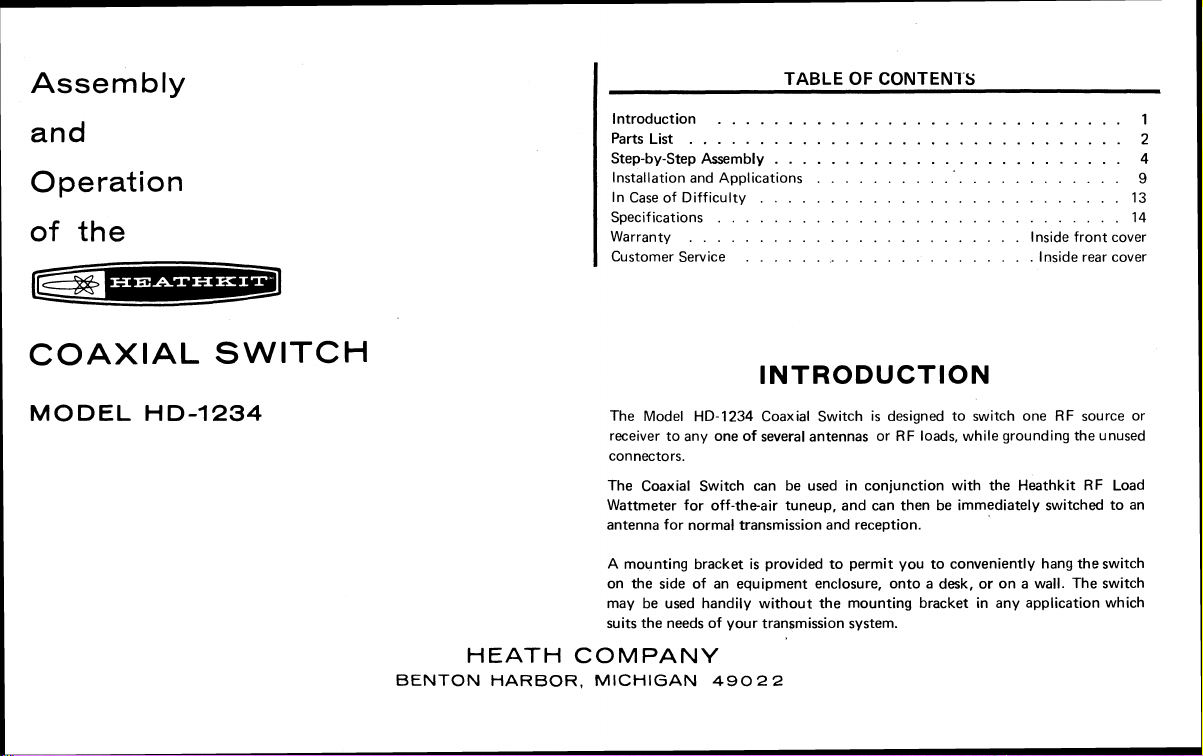
Introduction
Parts List
Step-by-step Assembly
Installation and Applications
In Case of Difficulty
Specifications
Warranty
Customer Service
.............................
...............................
.........................
.........................
.............................
........................
.....................
TABLE OF CONTENl'S
......................
Inside front cover
Inside rear cover
1
2
4
9
13
14
COAXIAL SWITCH
MODEL
HD-1234
BENTON
The Model HD-1234 Coaxial Switch
receiver to any one of several antennas or RF loads, while grounding the unused
connectors.
The Coaxial Switch can be used in conjunction with the
Wattmeter for off-theair
antenna for normal transmission and reception.
A
mounting bracket is provided to permit you to conveniently hang the switch
on the side of an equipment enclosure, onto a desk, or on a wall. The switch
may be used handily without the mounting bracket in any application which
suits the needs of your transmission system.
HEATH
HARBOR. MICHIGAN
COMPANY
INTRODUCTION
is
tuneup, and can then be immediately switched to an
49022
designed to switch one RF source or
Heathkit RF Load
Page 4
Page 2
KEY PART PARTS
No. No. Per Kit
--
-
METAL PARTS
HARDWARE
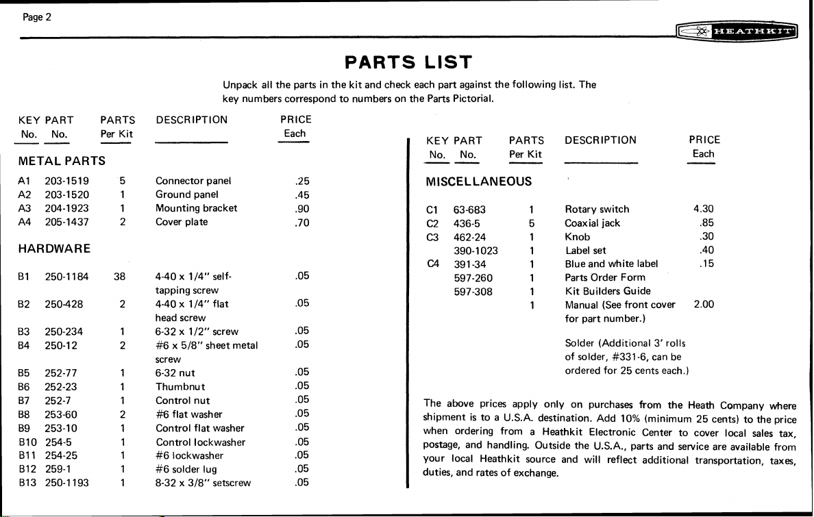
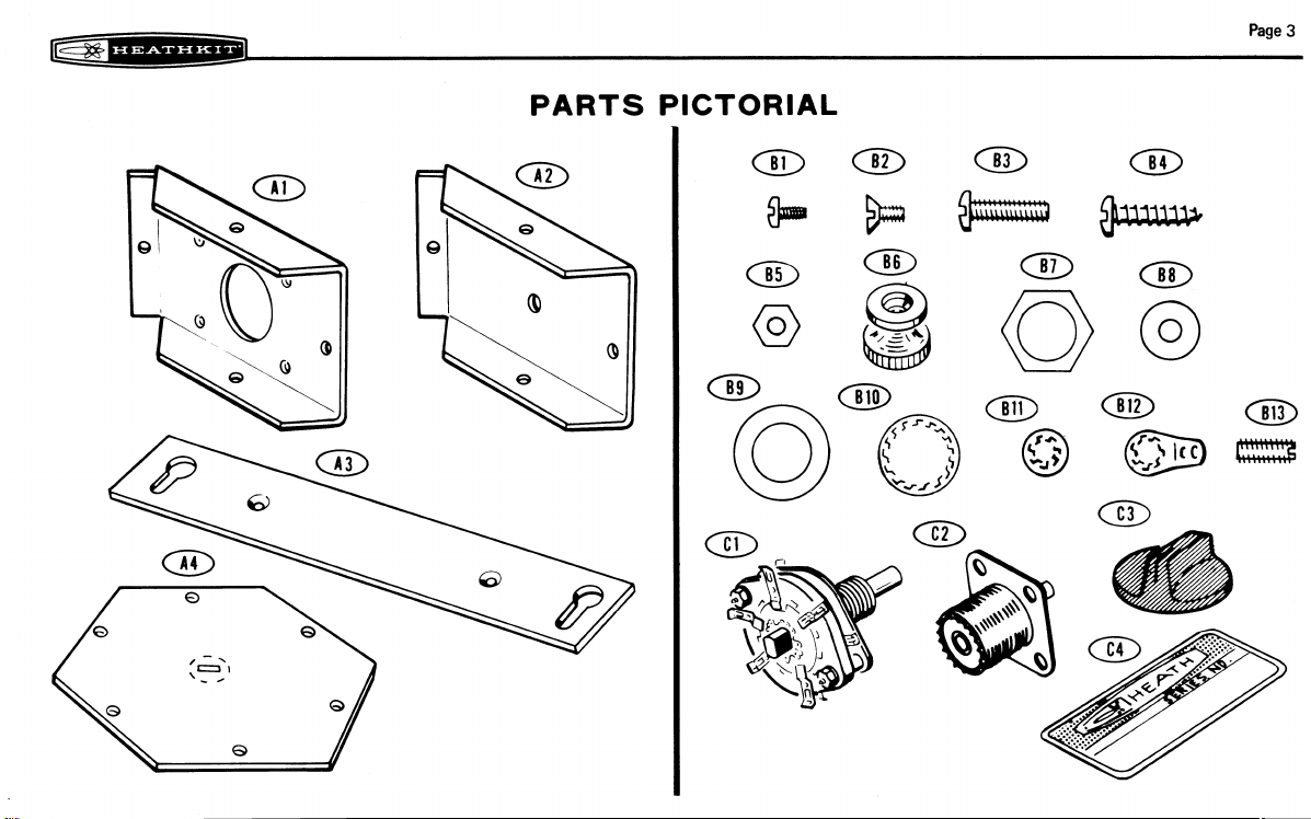
Unpack all the parts in the kit and check each part against the following list. The
key numbers correspond to numbers on the Parts Pictorial.
DESCRIPTION PRICE
Connector panel .25
Ground panel .45
Mounting bracket .90
Cover plate .70
4-40 x
114" self- .05
tapping screw
114" flat .05
4-40 x
head screw
112" screw .05
6-32 x
#6 x 518" sheet metal .05
screw
6-32 nut .05
Thumbnut .05
Control nut
#6
flat washer .05
Control flat washer .05
Control lockwasher .05
#6 lockwasher .05
#6 solder lug .05
318" setscrew .05
8-32 x
-
Each
.05
PARTS
LIST
KEY PART PARTS DESCRIPTION PRICE
No. No.
--
Per Kit
-
MISCELLANEOUS
C1 63-683
C2
436-5
C3
462-24 1 Knob
390-1023 1 Label set .40
(24
391-34 1 Blue and white label .15
597-260 1 Parts Order Form
597-308 1 Kit Builders Guide
The above prices apply only on purchases from the Heath Company where
shipment is to a
when ordering from a Heathkit Electronic Center to cover local sales tax,
postage, and handling. Outside the U.S.A., parts and service are available from
your local
duties, and rates of exchange.
Heathkit source and will reflect additional transportation, taxes,
1 Rotary switch 4 30
5 Coaxial jack
1
Manual (See front cover 2.00
for part number.)
Solder
(Add~t~onal
of solder,
ordered for 25 cents each.)
U.S.A. destination. Add 10% (minimum 25 cents) to the prlce
#331-6, can be
3'
rolls
Each
-
.85
.30
Page 5
PARTS PICTORIAL
Page
3
Page 6
Page 4
STEP-BY-STEP ASSEMBLY
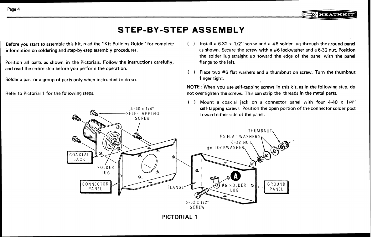
Before you start to assemble this kit, read the "Kit Builders Guide" for complete
information on soldering and step-by-step assembly procedures.
Position all parts as shown in the Pictorials. Follow the instructions carefully, flange to the left.
and read the entire step before you perform the operation.
a
part or a group of parts only when instructed to do so.
Solder
Refer to Pictorial 1 for the following steps.
4-40
x
SELF
114"
TAPPING
PICTORIAL
Install a 6-32 x 112" screw and a #6 solder lug through the ground panel
( )
as shown. Secure the screw with a
the solder lug straight up toward the edge of the panel with the panel
Place two
(
)
finger tight.
NOTE
:
not overtighten the screws. This
( )
Mount a coaxial jack on a connector panel
self-tapping screws. Position the open portion of
toward either side of the panel.
SCREW
#6
flat washers and a thumbnut on screw. Turn the thurnbnut
When you use self-tapping screws in this kit, as in the following step,
#6
FLAT
1
can
strip the threads in the metal parts.
WASHERS
#6 lockwasher and a 6-32 nut. Position
do
with four 4-40 x 114"
the connector solder post
Page 7

In the same manner, mount the four remaining coaxial jacks onto four
(
)
connector panels with 4-40 x
Add a small amount of solder to pre-tin each connector solder post.
)
(
2
Refer to Pictorial
NOTE:
In the following steps, you will .fasten connector panels and the ground
together. Be sure the flange end of each panel fits
panel
for the following steps.
114'' self-tapping screws.
we the panel to
which it is attached. Tighten each screw as it is installed; then loosen it
The screws will be tightened later.
Connect the ground panel to one of the connector panels with a 4-40 x
(
)
114" self-tapping screw as shown in Pictorials 1 and
2.
114 turn.
Page
5
)
Similarly, attach a connector panel to the other end of the ground panel
(
with a 4-40 x 114" self-tapping screw.
In the same manner, attach the remaining three connector panels to those
( )
previously assembled. Use four 4-40 x 1 /4" self-tapping screws.
)
Secure one of the cover plates to the connector and ground panels with six
(
114" self-tapping screws. Position the cover plate so the embossed
4-40 x
lettering is visible on the outside and so the embossed
G
is adjacent to the
ground connector as shown. Note the position of the solder lug.
)
Tighten the six cover screws. Then tighten the six screws that connect the
(
six connector and ground panels.
Turn the assembly so the cover plate is up. Bend the plug out of the center
( )
of the cover plate with the blade of a screwdriver.
SELF-TAPPING
PICTORIAL
2
CONNEClOR
NOTE. FLANGE
IhSI
DE
Page 8

Page 6
0
6
PICTORIAL
LOCKWASHER
CONNECTOR
FLAT WASHER
3
UND
Refer to Detail
NOTE:
that there is one long contact lug on the switch wafer at
notch in the rotary center portion of the switch.
Grasp the switch shaft with a pair of pliers and turn the switch rotor until
(
)
the long contact lug and the rotor notch are positioned together as shown
in the Detail. Do not turn the rotor again until the knob has been secured
to the switch shaft.
Carefully bend each of the lugs so
(
)
surface.
Refer to the Pictorial and carefully insert the rotary switch into the switch
(
)
housing assembly; the switch lug will easily drop through the corner
openings in the assembly. Rotate the switch and position the long contact
lug near the ground lug inside the housing as shown.
Place the control flat washer and the control nut on the switch shaft; do
)
(
not tighten the nut.
Reach inside the housing and turn the body of the switch until the long
(
)
contact lug is directly under the ground lug as shown in Detail
that one single lug on the front of the switch wafer will be under the
connector center conductor at
be in a position above and below each of the remaining four connector
center conductors.
Hold the switch firmly in this position and tighten the control nut.
(
)
3A
and to Pictorial 3 for the following steps.
Carefully study the rear of the rotary switch
it
is flat and straight out from the
D.
The remaining pairs of switch lugs will
as
shown in Detail
B,
and also there is a
3A.
3A
Note
Note
(
)
Bend the ground lug downward with the blade of a screwdriver until
touches the long switch lug. Solder the two lugs together.
it
Page 9

re*:w---=*-
Page
7
GROUND
(
I
Bend the remaining rotary switch lugs until they all touch the center
conductors of the coaxial jacks. Solder all five of the coaxial center
conductors to their respective switch lugs. NOTE: Be sure that both the
top and bottom switch lugs are securely soldered. Use enough solder to
sure the job is well done, but avoid an excess that will short the inner
conductor and switch lugs to the housing assembly.
4
Refer to Pictorial
for the following steps.
i'6~
Detail
3A
be
PICTORIAL
,
Secure
the
8-32
remaining
x
(
assembly with six 4-40 x
embossed markings are toward the outside of the housing.
Start an
( )
cover
plate
114''
318''
setscrew in the tapped hole of the knob.
4
to
the
self-tapping screws. Turn the cover so the
rear
of
the
switch
housing
Page 10

Page
8
rek*---=*:-~J
Refer to Pictorial 5 for the following steps.
(
)
4-40
x
114"
FLAT HEAD
SCREW
/
BRACKET
Place the knob on the switch shaft so the pointer is toward
the setscrew in the knob securely. You may now rotate the switch as
desired.
NOTE: You may wish to hang the Coaxial Switch on a wall or on an equipment
enclosure. A mounting bracket has been furnished for this purpose. Any two of
the opposite screws holding the rear cover plate may be removed to install the
mounting bracket in the following step. If you do not wish to use the mounting
bracket, skip the next step and also the third step (which tell you to install the
mounting bracket).
Note the numbers on the top cover and remove the two screws opposite
)
(
( )
( )
"2"
and the "C".
the
Place the blue and white label on the rear cover so the stamped numbers
are positioned
the label in this manner will permit you to read these numbers after the
mounting bracket is installed. NOTE: The Model Number and Production
Series Number of your kit are shown on this label. Refer to these numbers
in any communications you have with the Heath Company about this kit.
Install the mounting bracket on the rear cover plate with two
flat head screws as shown in the Pictorial.
as
close to two adjacent screw heads
as
@
.
Tighten
possible. Positioning
4-40
x
114"
- -
SETSCREW
This completes the "Step-by-step Assembly" of your Coaxial Switch. You will
be
instructed to apply the decals from your label set during the "Installation and
Applications" section which follows.
Page 11

C~=*:*-.L=*~@
INSTALLATION AND APPLICATION
NOTE: There are many ways that your Coaxial Switch may be installed and
there are various applications for its use. One method for installing the Switch is
outlined below, and two methods for its use will be covered. Your individual
needs will dictate your specific application.
INSTALLATION
Refer to Figure 1 for the following steps.
Page
9
Place the Switch against the wall or panel where
( )
the tip of each keyhole slot in the mounting bracket on the selected
surface.
( )
Drill 3/32" holes at the marked locations.
)
Turn the two
(
of the shank is showing. Hang the mounting bracket onto the two screws;
then tighten the screws securely.
(
)
Loosen the thumbnut on the ground connection screw. Place the
earth-ground lead between the two flat washers; then tighten the
thumbnut securely.
k6
x 518" sheet metal screws into the holes until only 1/8"
it
is to be installed. Mark
BAR
Figure
1
Page 12

Page
10
APPLICATIONS
Refer to Figure 2 for the following steps.
TO
D
I
POLE
ANTEIUhA
c-=-*---&J
Primary Method
Connect a dummy load to connector
)
(
a reflected power meter, if one is used) to the C (common) connector.
Then connect from one to three antennas to connectors
#4.
Connect the transceiver (through
#1
Alternate Method (requires two Coaxial switches)
Refer to Figure
(
)
Connect the C (common) connectors of two coaxial switches together
with a length of
units to connectors
up to three antennas to connectors
switch.
1'
(
i
select the appropriate decals in your label set. Remove those selected, one
at
embossed circles on the front panel of the switch assembly, Position them
so they are vertically aligned as you look at them.
be omitted if desired.
3
for
the following steps.
RG-8/U coaxial cable. Connect up to three transceiver
#1
through
#3
on one Coaxial Switch. Then connect
#I
through
hen you have chosen the arrangement that best suits your requirements,
a time, from the paper backing and press each into place over the
#3
of the other coaxial
NOTE:
This step may
through
#3.
TO
TRI
AhTtNhA
-BAND
-LOAIIAL
CABLE
1
Figure
TO
CAhTEhNA
DUMMY
LOAD
TO
TRANSCEIVER
[THROUGH
REFL.
2
Page 13

Page
11
TRAhSCEI VER
LJ
RECEl VER
m
TO
OR
DUh\MY
-=COAXIAL CABLE
-
=
G
R 0 U
Figure
N D W I R
3
E
TO TRIBAhD
ANTENNA
TO INVERTED
===+
CAN~ENNA
LOAD
This scan is not authorized to
boupht hs scanned manual on eBay, then
bought
it
Please file a complaint with eBay and demand a refund.
&om is a hef who sold you stolen
Dl
POLE
TO
ANTEkI'.A
be
sold on eBay. If you
the
vendor you
property.
ANTENNA
-V
Page 14

Page
12
@$b=**--4*5--3
OPERATION
Refer to Schematic Diagram, Figure
When the switch knob
output connectors are grounded except the C connector. WARNING: DO NOT
OPERATE THE TRANSMITTER INTO THE COAXIAL SWITCH WHEN THE
POINTER IS AT THE
of
either
these positions, the transmitter is connected to an open circuit.
is
@
4.
rotated to either the @ or the @ positions, all
OR THE @ POSITION. When the Switch
is
in
ROTARY
SWITCH
m
REAR WAFER ,FRONT WAFER
I
t
I
Figure
4
I
I
Page 15

@@*:*---=*:.+a
IN
CASE
OF DIFFICULTY
Page
13
There are only two possible difficulties that can be found in the Coaxial Switch,
with the exception of parts failure. These would be either an open circuit or a they are properly grounded, or are connected through from input to output as
shorted circuit when the opposite should be the case.
In either event, remove the rear cover from the switch assembly and carefully
inspect each solder connection. Be sure that no solder has run from any of the
center conductors to the metal parts of the assembly. If a circuit is known to be
open, try moving the switch lugs where they touch the coaxial jack center
conductors. Be sure both the upper and lower switch lugs not only make contact
with these center conductors, but that they are well soldered and immovable.
Finally, check each of the coaxial jacks with an ohmmeter and make sure that
they should be.
It is suggested, if there still appears to be a problem, that you reheat each solder
connection and melt a small additional amount of solder onto each connection.
Then recheck the Switch for proper continuity with an ohmmeter once again.
Page 16

Page
14
SPECIFICATIONS
IF
%
w**:*d
Standing Wave Ratio (to 250 MHz)
Power Capability
The Heath Company reserves the right to discontinue instruments and to change
specifications at any time without incurring any obligation to incorporate new
features in instruments previously sold.
....................
............
1.1
:1
maximum.
1000 watts (2000 watts PEP) maximum
Page 17

L
EXPEDITED PARTS ORDER
(FOR REPAIR PARTS ONLY)
NAME
FORM
PLEASE DO NOT WRITE IN
1
THIS SPACE
ADDRESS
CITY
I
KIT MODEL PURCHASE DATE INVOICE NUMBER LOCATION PURCHASED
I
QTY.
-
r
I
INSTRUCTIONS:
(MINIMUM
AUTHORIZE PERMISSION FOR C.0 D. SHIPMENT (MINIMUM ORDER SHIPPED
C.0.D IS
MICHIGAN RESIDENTS ADD
HEATH
PART
NUMBER
INCLUDE CHECK OR MONEY ORDER FOR TOTAL PARTS ORDERED ADD
$0.25)
$10.00).
FOR INSURANCE, POSTAGE AND HANDLING.
STATE
4%
SALES TAX
ZIP
DESCRIPTION OF PART
rn
THlS FORM IS FOR U.S. CUSTOMERS ONLY. OVERSEAS CUSTOMERS SEE YOUR DISTRIBUTOR.
10%
SEND
HEATH COMPANY
BENTON HARBOR,
I
MICHIGAN
ATTN PARTS REPLACEMENT
TOTAL
PRICE
C.O.D. AUTHORIZATION
DESIRED METHOD
EDITORS INITIALS
SIGNED
49022
I
OF SHIPMENT
Page 18

Page 19

Page 20

Schlumberger
lii9
LIMO
IN
USA
*
 Loading...