

Page 1
Heathkit Troubleshooting Tips
AA-Series Amplifiers
AA-22
• SPST pushbutton power switch breaks down quite often.
AA-29
• Hum and noise audible w/volume turned up and covers taken off: This is normal (approx. 3mV @ 8
ohms measured with IM-48).
AD-Series Audio Equipment
AD-17, AD-19, AD-27, and Other Systems w/BSR-500 Changers
• Slow Speed and Slow Changer Action: Changer may even stop during change cycle. Check idler wheel
height adjustment. Replace idler wheel if it has a "hardened" appearance. Clean idler wheel, pulley, platter,
and changer mechanism with a non-lubricating solvent (Print-Kote®). Don't use tuner contact cleaner as it
usually contains silicon lubricant. Soak the bearing assembly in solvent (the assembly at the base of the
spindle). Lightly oil this bearing assembly and the cam next to it after cleaning. Check speed with a strobe
disk. Clockwise movement of the markers indicates a slightly fast rotation (normal). CCW movement is too
• slow. (Contributed by John D'Amore, former Heath Field Service Manager.)
•
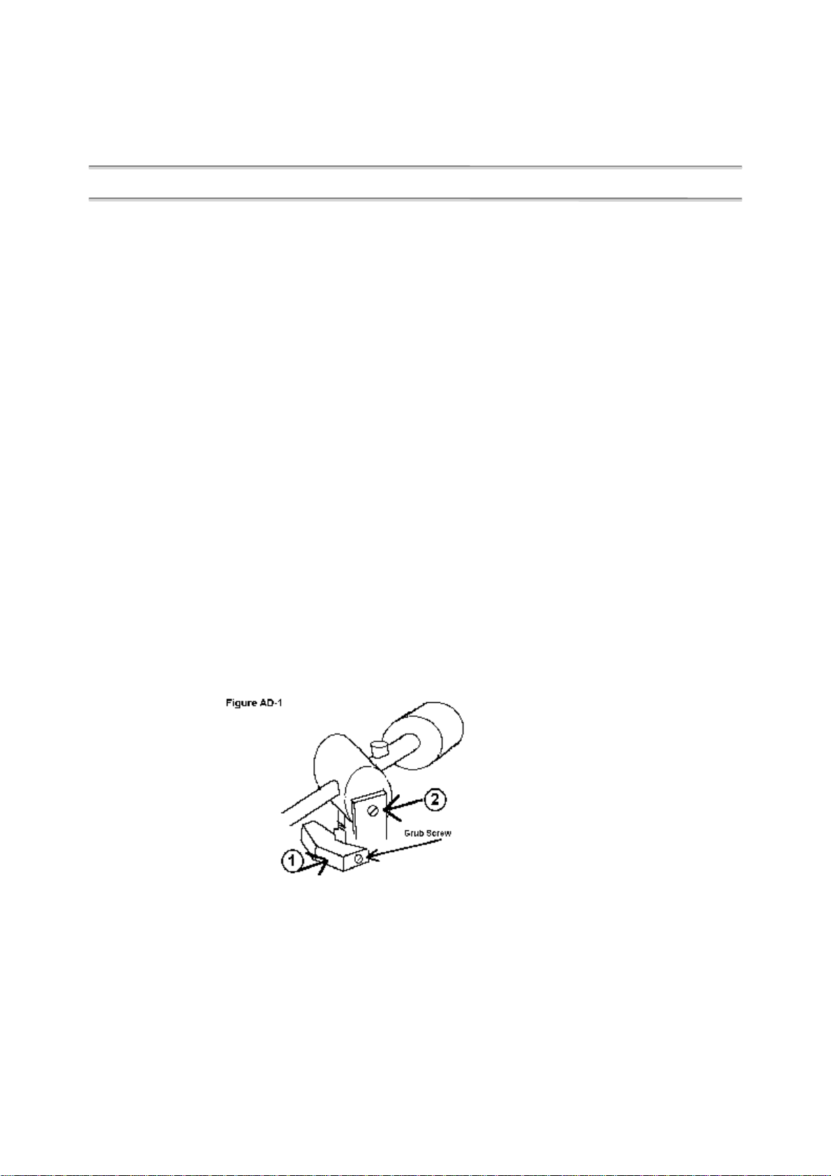
• Tone-arm won't clear raising pad, cuing lever operation jerky (see Figure AD-1): At first appearance,
it's the rising pad (location 1), however, check the pivot screw (2) to make sure it isn't too tight (this also
has some effect on tone arm setdown).
• Tone-arm behaves normally halfway across LP, then sticks--playing the same groove over and over.
Manually moving the tone arm inward about 1/2" fixes: This is due to grossly misadjusted anti-skate
adjustment, causing the antiskating spring to latch on to one or more protuberances.
AD-17, AD-27
• Stylus #236-202 NLA. Replace entire cartridge, #236-201.
AD-27
• Parts for the turntable can also be found in the AD-17 manual.
AD-110
• Excessive meter deflection, left channel, in record mode, w/recorder level turned up and service
bulletin #AD-110-1 doesn't help: Check C2. Place the banded end to ground. This is the outer foil and
Page 2

provides shielding to prevent coupling from R66s bias cable to C2. Also, reposition the wires from R34 as
far from the slide switch as possible (consider using shielded cable).
• Normal bias adjustment levels are about 25-28 Vrms at yellow wires of head. Dropping to about 16 Vrms
improves high frequency response but causes distortion.
• The VU meters are used in record only--not playback.
AJ-Series Tuners
AJ-15
• Motorboats with headphones plugged in: Check Q503--may be shorted.
• Voltage Measurements
I.F. Voltages:
Q305
--- C = 10.5 V
B = 2.5 V
E = 1.7 V
IC-301
------ - 1 = 2.3 V
- 2 = 2.3 V
-10 = 9.8 V
- 3 = 2.3 V
- 4 = 2.3 V
- 5 = 9.2 V
IC-302
------ - 1 = 2.3 V
- 2 = 2.3 V
-10 = 9.0 V
- 4 = 2.3 V
- 3 = 2.3 V
- 5 = 6.0 V
AJ-29
• No muting action: Check for leaky ZD-211.
AJ-33
• DPDT slide switches tend to open up or make intermittent contact: 50-50 chance of being cured
w/contact cleaner. Also, the clamps holding the phenolic backs can be tightened.
AJ-43D
• The effect of the SCA filter switch is very obvious: With this switch off, a high-pitched whistle can be
heard in the background on stereo programs.
AM Through AP-Series Audio Equipment
AN-2016
• Separation approximately 25 dB on Aux, Tape, and Tape monitor inputs: This is normal. The coupling
capacitance between any disconnected unshielded input (or tape output) line to the rest of the wiring
harness measures about 30 pF.
AR-Series Receivers
AR-13
• Motorboats at turn-off: Check for bad C17-C18 (both capacitors are in the same can).
• Dim stereo lamp: Check for open C16.
• AM oscillations: High end too sensitive--back off the RF and antenna trimmers to fix--will stay in specs.
Page 3

AR-15
• 1 MHz oscillation at speaker output: Check 201 or 202 for leakage. Or miswired transistor sockets.
• AM or FM dial cord jams: Try repositioning the respective tuning shaft bracket. As the tuning shaft is
moved backwards, there's less of a tendency to jam when rotating dial.
AR-29
• No mute function: Check for leaky ZD-211.
AR-1500
• Poor FM sensitivity: Check screw at coax ground lug on tuner assembly. Should be 6-32 x 1/4". If 6-32 x
3/8", the screw will short C802 (antenna trimmer) to ground.
• FM-IF DC voltage and relative RF levels: Set the FM signal to about 100 mV, modulated w/1 kHz,
deviation ? kHz at 88 MHz. Adjust the output to give an approximate level (RF) of 0.4 V p-p at IC-201, pin
6. Use a 10 MHz scope or better and a low-capacitance X10 probe. This should show the following levels
(dc-volts w/vtvm):
Component DC Volts P-P RF (10.7 MHz)
--------- -------- ----------------IC201-3 1.5 V 0.1
IC201-6 10.7 0.4
R202 0.2
Q201 base 1.0 0.2
Q201 collector 3.3 0.5
IC202-1 2.2 0.5
IC202-5 7.2 0.9
R210 0.3
IC203-1 2.2 0.3
IC203-5 7.0 2.5
T201-3 0.3 (audio)
• AGC and meter circuit levels. (Same setup as before.)
Component DC Volts P-P RF (10.7 MHz)
--------- -------- ----------------Q204 base 0.7 0.5
Q204 collector 3.2 5.0
Q205 collector 12.3 7.0
R230, C228 -4.8 0
D201, D203 0 6 VAC (P-P)
D201, D202 0.8 0
R225 to meter 0.14 0
• Note: The previous two sets of measurements do not hold true for the AR-1500-A model. In the "A"
model, C220 was changed from 0.05 uF (X
load on Q201s collector and a smaller RF signal (0.1 V P-P) is developed at Q204s base. A smaller AGC
voltage is developed, so that the signal at Q201 collector is greater (about 1.5 V P-P). Thus, for the same
level of incoming signal, the S-meter on the AR-1500A may indicate a lower level.
=0.2975 ohms) to 10 pF (XC=1.487 kilohms). This reduces the
C
C-Series Automotive
CI-1079
• TI brand IC 443-7 may not always work here: Replace with Fairchild brand 443-7.
CO-1015
• Cal position shows 2 cycles for a brief period: Normal--can be speeded up somewhat by selecting D401
with a higher reverse resistance.
• Non-linear sweep: Check for leaky Q402.
• Non-linear sweep: Check C401 by substitution (bad one gives slight non-linearity but won't open eye of
capacitor checker).
CO-2500
• Tachometer jitters: This is normal.
Page 4

• Intermittent tachometer operation or no operation on motors other than 8 cylinders: Check for spread
sockets on pins 1 and 8 of IC-203. If too heavy of wire is used during calibration, the above may occur.
• TI brand IC 443-7 may not always work here: Replace with Fairchild brand 443-7.
• Different balance voltages with modified board--R136 from 47 ohms to 33 ohms. R123 from 22 kilohms to
47 kilohms.
E-Series Educational Products
ET-3400
• Intermittent or no display: Check for good ground at IC6, pin 6.
G-Series Digital Clocks
GB-1201
• Count jumps a second or more when loading a number from function 5 to function 6: Replace the
rotary switch, SW3. Be sure the insulation beneath it is installed. Note that the reset button must be set in
function 5 prior to counting up a number.
GC-1092
• One number brighter than others: Check D217 through D223 for leakage.
• No DC-upverter operation after modification: Replace Q201 with a 417-233 (2N3643).
GC-1093
• Improved dynamic range for automatic dimming circuit: Change R8 to 15 kilohms.
• Erratic operation: Make sure the customer didn't use conductive foam tape (supplied with some clock
chips) for the padding between the crystal and the chip.
• Blue flare on AM or PM display: Check for leaky Q2--pulse must be about 11 V P-P.
GD-Series Radio Control
(Note: If I remember right, I got most of the following information from Bob Ellerton, who was a Heath Technical
Consultant at the time and an RC enthusiast. Later, he was promoted to Factory Service Supervisor for the
computer product line. Sometime after that, he took over as Manager of the Heath User's Group.)
General
• Interference may occur when the receiver is installed in the airplane, but not in the shop: This may be
due to metal-to-metal contact in the plane (push rods, etc.), rubbing due to vibration and generating
electrical noise (see pg. 27 of GDA-1205-7 manual).
• Jittery Servos: This can be caused by the motor wiring. If 180-degree rotation occurs, try reversing the
connections to the motor before replacing.
GDA-19-4
• Servos are sluggish or have poor torque: The rack gears may be slightly out of tolerance. Also, observe
left-right pairing of rack gears (for proper centering).
• Sluggish in one direction, will rotate nearly 180 degrees with servo simulator, centering standard
causes rotation in one extreme direction: All this is due to a dead monostable multivibrator. Check that
the red wire to C8 is wired to the center tap and not the tap opposite the green wire.
GD-Series Small Items
GD-39
• Q10 should be 0.25 V saturated.
GD-48
• Marginal operation: Clean the search coil circuit board. Check C6 for leakage. IT-28 "eye" should open in
5 to 10 seconds.
• Oscillator is temperature sensitive and may not work in extreme cold or heat.
Page 5

GD-113
• Intermittent oscillations in transmit: Tighten the hardware to the switching board--the bracket--strap and
solder with braided shield if necessary.
GD-348
• Metal locator won't null properly, appears sensitive to the shaft: This may be due to improper
capacitance on the spiral cable in the shaft. Try a capacitor-substitution box across various combinations of
points A, D, Y, F, and G on the audio circuit board (if replacing the cable doesn't correct). Placing a 0.02
uF ceramic disc (21-82) from "D" to "Y" on the audio board on series #01306 corrected.
• Won't null: Check signal voltage drops across R106 and R104. If no replacement search coil available,
shunt R106 with cap in the 12-25 pF range (such as 20-77 mica) (24 pf).
GD-1112/GD-1162
• Receives but won't transmit: Check Q1 (417-283). Can be either of two types--bases and collectors
reversed--see pg 22 of assembly manual.
GD-1150
• Normal Operation: No load draws about 0.3 to 0.4 amperes. One inch of water with an object will draw
0.5 to 0.7 amps.
GDA-1158-3/-4
• 60 Hz modulation of the 40 kHz/56 kHz carrier (amplitude): Replace Q102, Q103, and Q105 with 417-
118s (2N3393). The B-1097s that are supplied have a beta of >250 which appears to be the cause.
GD-1185
• Display won't blank when "E/R" pressed (step 11, pg. 82): Check IC-1111. Measure IC-1111 with an
IM-4100 and x10 probe (PKW-101) in the "totalize" mode. X10 atten will normally read "8" (E/R pressed),
IC-1101 bad may read 16.
• Normal operating characteristics:
IC-1106-3: freq=1,733 kHz to 1750 kHz; pulse count=8 pulses
IC-1111-4: freq=108 kHz to 110 kHz; pulse count=8 pulses
IC-1111-6: same as IC-1111-4 except for a + or - 2 digit error
on the count.
GD-1187
• Do not use an isolation transformer--touch switch may not work properly.
General Audio
Differential Power Amps
• Most Heath differential power amps (AA-1640, AR-1500, AA-29, etc.) can be initially (and safely) tested
by removing the load and output transistors. The drivers should reproduce a waveform as it normally
would. If not, several expensive components have been saved from destruction.
Tape Dubbing Test
• Tape Dubbing Test for New Audio Equipment: Plug a set of stereo headphones into the dubbing input.
Activate the dubbing switch. Previous signal at the output should disappear. Turn the volume to near
maximum. Tap the left and right headphone. A faint tap should be heard in the left and right speaker. Plug
the headphones into the dubbing output. Feed a signal into a function switch-selected input (such as "AM"
or "FM"). The signal should be faintly heard in the headphones. Reduce the volume setting and return the
system to normal.
Page 6

GR-Series SWL and Ham Receivers
GR-78
E-band dead on low end: (A) Replace Q301 with 417-167 (see above). (B) Change R304 to 1500 ohms. (C)
Change R303 to 2200 ohms. (D) Swap L303 w/2200 ohms (prevents FMing when switching to "C" band).
• When aligning the unit, be sure the top cover is in place or the C, D, E, and F bands my break into parasitic
oscillation.
• E-band extremely touchy in alignment of the oscillator--both high and low end: This can be caused by
missing jumper wire from SW-301B, pin 8 to the circuit board solder run (L305, R303, etc).
• Align the E and F bands first: If Q301 does not function properly, it can be replaced without having to re-
align the entire unit. Do not attempt alignment without the top cover or the bottom switch-board shield, or
without the switch shaft installed. All of these will affect the local oscillator frequency.
• E and F bands dead on the low end: This may be due to a low gain-bandwidth product of Q301, so that
with the lower Q of C305-L305-R303 (on E) and C306, L306, R304 (on F) when tuned to their respective
low ends prevents enough positive feedback to maintain oscillation. To cure, try removing R303 and
replacing the 2200 ohm at R304 with a 5600 ohm resistor. If this doesn't work, try the unauthorized
modification shown with the illustration, above.
GR-110
• TI brand 443-7 will not always work here. Use Fairchild.
• Q101 and Q102 will measure 4 volts on gate two w/33 kilohm resistors at R102 and R105 (used to be 15
kilohms).
• Priority oscillator won't "catch" channel "0" signal: Replace IC-105.
GR-Series Television
GR-104
• Faint vertical bars: Check C232.
• High voltage drops with the brightness turned up--similar to low horizontal drive: Check for open
L201.
GR-300, 400, and 500
• No AFT: The AFT assembly may be installed backwards.
• AFC erratic; picture loses sync, picture polarity reverses: Problem occurs when changing channels.
Corrects itself when turning the TV off or on: Check L327--should be to tuned to 2nd peak from the top.
GR-900
• Luminance board #85-365-6 same as #85-365-9 except for Q254 in the dot generator and can be
interchanged for most purposes.
Page 7

• No 3.58 MHz from the oscillator circuit board but the transformers and active components are okay:
Check for an open D406.
• Loss of interlace after 1/2 to 2 minutes of operation--sides pull in: Waveform at pin 2 of horizontal
oscillator board about 2 V P-P sawtooth. Check for open L552.
• Boards check okay for any kind of problem, wiring appears correct: Check the wiring harness at the
breakouts. Now and then, two or more wires will pinch together (possibly at time of harness construction).
• No dots: Check for leaky C701.
• Intermittent horizontal jitter: Check C563.
• No AFT--adjusts okay: Check for reversed black and red wires on red chassis plug.
GR-2000
• Preset tuning controls unable to adjust from low end of Lo-VHF to high end of Lo-VHF (ditto for Hi-
VHF): Check collector voltages of Q201 through Q216. Only one should be high. If not, the cathode
voltages of D249 through D264 cannot be properly controlled by any single tuning potentiometer. Outside
of bad solder connections or open transistors, check for open/defective transistor sockets.
GR-2001
• Clock oscillation: (1) Put ferrite bead on Q53 collector. (2) Change C114 to 0.001 on memory board of
programmer.
H-Series Computers
H8
• Check for shorts between runs on the mother board. Most common problem.
• +/-18 V supply failure next most common problem--possibly due to improper board installation (mem &
i/o).
• Female connector pins opening up is the most common cause of intermittents.
• Due to H8 construction, address/data lines go low when asserted.
H8-1/3
• Distribution tape loads okay, but some functions won't work; board passes memory tests: This can be
due to bad RAM. Swap IC's until symptoms change.
• 24K memory test: Set data at 040105 to 177.
Data Size
---- ---057 4 K
077 8 K
117 12 K
137 16 K
157 20 K
177 24 K
217 28 K
237 32 K
257 36 K
277 40 K
317 44 K
337 48 K
357 52 K
377 56 K
64 K
• Memory test with WH-17: See the note on memory testing the H17.
H8-5
• No 5-second pause prior to tape dump: Check the data bus driver.
H8-16
• Memory test with H8-17: See the note on memory testing the H-17.
Page 8

• Passes memory test but I/O locks up after return key is pressed when HDOS asks Action (BOOT):
Check for faulty U117.
H9
• Cursor intermittently skips when typing: Place a 36 pF (21-709) capacitor from S705-7 to ground on the
TPU board.
• CRT displays random numbers, cursor moves backwards on 1st turn-on: Try placing a 0.001 uF cap
from IC738-13 to ground on the TPU. (Contributed by Bill Sherman, former Heath Field Service
Manager.)
• Dim raster: Check for the presence of the CRT grounding wire--also may be loose. (Contributed by Terry
Bower, former Heath TV technician.)
• Scan excessively wide: Check for leaky D307, D306, and D305.
• Pulses appear to be present, but unit still malfunctions: Check the associated wiring harness--if a wire is
open, other wires will capacitively couple a signal over.
• Three cursors: Check for open P403-13.
• No Auto-carry defeat: Check for short to ground on S705-4.
• Cursor homes to lower right corner--won't advance--prints character: Make sure P701 is plugged in.
• Cursor constantly moving: Check for open run to IC734-5 (TPU).
• Column move to far right of page during Auto-carry and scroll in short form: Check for open pin 8 on
IC528.
• Cursor won't home after transmit page: Check IC513.
• Page filled with "?": Check for open write-enable line.
• Cursor skips spaces in a "binary" manner: Check for shorts between pins 9, 10, 15, and 16 of cursor
latch IC501.
• No scroll: Check for interchanged blue and green wires to S503-5 and -6 beneath the picture tube. Green
should go to S503-5.
• P603 pin-out (rear view):
• 20 mA current loop (passive):
• I'm not sure how I used the above circuit to test the H9 20 mA passive current loop function. Apparently, I
plugged the dual bananna connector into a 20 VDC power supply and did something with the switch. The
Page 9

switch may represent a keyboard key and pressing it would echo the character back to the screen. (ww 6
July 1996)
• Cursor advances only 10 spaces and then returns to the beginning of the line: Check for data flow
from IC-502 to IC-504B to IC-509.
• Only character displayed is at the upper left corner--cursor won't advance: Check for a short circuit
between S502-1 (cursor latch enable) and S502-2 (select scroll divide-by-12)--on the top of the chassis
below the CRT.
• NOTE: Many of the problems in the H9s were due to the fact that the spring connectors on the factory-
built wiring harness were pinched onto the wires rather than soldered. If you're attempting to restore one of
these terminals, you may need to remove the connectors from their shells and solder them. (ww 30 June 96)
H10
• Drops or adds an occasional bit of data (reader): Be sure that the retainer beneath the tape lamp is flat
against the bottom of the tape guide. Check that the bulb filament is horizontal and directly above the
reader holes.
• Drops or adds bits of data--reader/punch: Be sure the power supply switch is in "normal." Also check
that the slide from the reader slot is low enough that fan-fold paper tape won't catch on the top--causing the
sprocket to momentarily skip.
• NOTE: When punching tape, the solenoids in the early H10s would tend to jam and tear the paper tape.
This was because they would heat up and the shafts would warp. Heath Company fixed this by changing to
a more reliable part. Sorry, I have no memory of what the part numbers are. (ww 30 June 1996)
H14
• Passes initial test, intermittently passes initial "on line" test but print head only moves back and
forth continuously with all ICs installed and the on-line button pressed: Check for a short between data
lines D6 and D7.
H17
• Motor clatters: Check for a short circuit between U8A-3 (writegate-low) and U7B-3 (readdata-low).
• Memory can be tested by using the program at 030 003A in PROM:
(A) Set PC=030003
(B) Press "Go."
The HL registers now contains the starting address 040100A. The DE registers contain the ending address-
-64 bytes below the stack pointer location in upper memory. If desired, both can be changed.
(C) Monitor the B register.
If a failure occurs, the B register contains the byte that failed while the HL register points to the address
that failed.
• AT: address: 374Q
• No I/O response after Return key is pressed for "Action (BOOT)" prompt: Check for a faulty U117 on
the H8-16 board.
H27
• Door assembly replacement: #969-34 (G-288, Dec. 22, 1978).
• Complete drive part number: #150-73.
H-Series Ham Equipment
HD-1982 and HW-2036
• 5 kHz deviation adjusts to about 11 o'clock as seen from the front. Setting the micoder level will then give
about 2 kHz deviation at 9 o'clock.
HD-1982 and HWA-2021-3
• The LEDs appear to be heat sensitive and may be destroyed easily with a too-hot of an iron. Use a heat
sink.
Page 10

HG-10B
• The key jack in the back of the unit is used only for cathode keying--see page 32 (Operation) and page 28,
1st paragraph.
HM-102, HM-103
• The wattmeter portions are usually tuned for 7 MHz (40 M). For other frequencies, a correction factor
curve should be calculated using a dummy load, RF probe, and VTVM. The equation is:
P=E2/R
HM-2102
• SWR won't null: This is due to too much capacitive loading to the brass eyelet from L1. Remove C16 and
the brass eyelet (in extreme cases).
HN-31
• To prevent accidental oil spills: Use 1 part mineral oil to 4 parts paraffin (melting point about 135
is either from a factory modification, or I'd seen it in some trade journal. I've never tried it myself. --ww 8
Jul 96)
HR-10B
• No AVC, no S-meter movement with received signal: Check terminal strip A (pg. 1, pict. 15). May be
installed backwards. (A service bulletin covers this.)
HR-1680
o
F). (This
• Check for missing 3900-ohm resistor on the power supply board.
• Pre-selector oscillates: Adjust pre-selector wires with 50-ohm non-reactive load on the antenna.
HW-8
• Won't tune: Q11 may be installed backwards.
HW-16
• A quick and dirty technique to check over-all receiver accuracy and 80-meter sensitivity is to tune to
3.579545 MHz using a short piece of wire for an antenna. If there is a color TV operating nearby, the
receiver should be able to pick this up and zero-beat to it.
HW-32
• It's normal for there to be as much as 3 dB power difference between the USB and the LSB.
• Normal power output is 25 to 50 watts (power appears to be higher on LSB and low end of band).
HW-32A
• Relay chatters in VOX mode: Remove C203.
HW-100
• Instability: See service bulletin GH-1, dated July 10, 1968.
• Audio pre-amp and VOX info: See bulletins #GH-3 (July 7, 1969) and GH-2 (Aug 20, 1968).
HW-101
(A couple of these are my own, but most came from Engineering, Tech. Consultants, Heath technicians, and field
technicians. The HW-101 was a great transceiver, but it was truly an art to repair one that was broken.)
• Receive audio amplifier oscillates with RF gain set to 2 o'clock: Check for open R323 at V14A.
• No RF out: Check for interchanged R938 and R916 (near V9 and V8).
• R14 and R112 cooked: White-blue and White-blue-blue wires on RL-2 may be interchanged.
• R223 and R109 cooked: Check for short across C111.
• RL2 keys after warm-up: Check for leaky D202 at V12B (56-25).
• Low power output: This is affected by the placement of the grounds on the shields in the HFO stages. The
rear shield is the most critical. Remove the "fingers" on the rear shield cover. The power can be tuned for
maximum output by properly positioning the grounding solder.
Page 11

• Microphonics on receive calibrate: This is normal if they occur when the unit is jarred.
• 7 MHz and 14 MHz (40 & 20 meters) bands dips instead of peaks (rcv & xmit): This is the combined
effects of L702 through L705 and/or L802 through L805. Selecting coils for the offending board may help.
In one case, the culprits were the 21 MHz (15 meter) coils.
• Low power output, all bands, worse on 10 meters: Try replacing the finals (V8, V9) with GE-brand
tubes. RCA-brand tubes appear to be the cause. Also, sub V7.
• Low power output at 40 meters: Check C703, C704, C802, and C803. May be out of tolerance.
• Oscillates on 15 and 10 meters: Be sure that the neutralization wire from the preselector isn't shorted to
ground. Check for good grounds on the shields of the drivers.
• Relay chatter in VOX mode: Replace the two wht/rd/rd wires to R213/R214 with shielded cable. Ground
the shields near R213/R214.
• High plate current, no RF power out on some bands--receive okay: Check for broken taps on L904.
HW-2021
An anecdote: In 1979 I was promoted from Senior Technician to Service Technical Writer and was transferred from
Omaha to St. Joseph, Michigan. There was kind of a fire going on and I was required to write service manuals on the
newly released H19 terminal and H89 computer.
After I finished them, my boss, Frank K., assigned me to write a manual on a new Heath 2-meter handy-talky. (I no
longer remember what the model number was.) Frank advised me to use the HW-2021 service manual as a guide. I,
with my vast experience of writing two service manuals, pointed out to him that while the HW-2021 manual was
good, I found it lacking. I went on at great length describing in detail how I could write a better manual.
When I finally stopped to catch my breath, Frank quietly said "I wrote that manual."
Meanwhile, our typist/proofreader/illustrator, Fran, was doing her damnedest not to bust a gut.
At the time, I didn't realize that I was still new and that Frank had many more years of servicing, writing, and editing
experience than I did.
Frank was okay, though. You begin to realize you have a good boss when you work for him for 13 years and even
turn down job offers from other departments.
• TVI: May be due to 45 MHz radiation. Disconnect the brown wire from hole "U" on the main circuit board
and reconnect at the hole near the emitter of Q15.
• The collector V
• Low power output: Make sure that the P.A. transistor is mounted close to the board.
• Offset switch damage occurs easily, check while servicing.
• Quieting is normally best about 1 kHz below minimum THD.
• Oscillator won't net: Change C57 to 56 pf. Also try changing the netting capacitors or the bias resistors to
the varactor diode (in extreme conditions).
• Receive oscillations: Check for a well-grounded clip at the antenna terminal. Build up a layer of solder on
the foil-side screw-hole rings on the circuit board to insure a good ground connection to the metalized
plastic case. To give a better ground contact for the antenna, place the flat washer on the antenna jack on
the inside of the case.
• Batteries won't charge: Check the spring assemblies in the battery pack. These can protrude and short to
the case.
• Transmitter alignment: Be sure the power supply voltage to the transmitter circuits are the correct levels.
Either use the battery pack or increase the external DC supply to the point that equals normal battery pack
operation. Otherwise, you'll get erratic results.
• 1 mH chokes (#45-80) are heat sensitive and can easily be destroyed.
• Erratic oscillator: Look for the 1 mH in the ??? circuit rather than the circuit of Q???.
of Q24 is normally lower than that of the collector of Q23. Other stages show gain.
RF
HW-2026
If I remember right, the HW-2026 caused some serious cross-talk problems in cities with repeaters that were close
together. At the time, the Heath engineers could not solve the problem (short of totally redesigning the unit). So the
Heath company contacted all their customers to recall the kit. The deal was this: If the kit wasn't built yet, Heath
would refund the customer's money plus pay an extra $25. If the kit was already assembled, Heath would refund the
money plus pay the customer $50 (big bucks in those days). If the customer chose not to return the kit, Heath would
not provide service or any other support.
Amazingly, many customers chose to keep the radio.
• Its spurs were -40db @ +/- 2 MHz of the carrier. The HW-2036 is -70db at +/- 20 MHz of the carrier.
Page 12

HW-2036
• Excessive spurs on 146.84 MHz and 146.76 MHz. Buries the needle with the cover on: Check L202 for
proper installation.
• Receiver spurs on 146.00 MHz, 147.00 MHz, and 148.00 MHz: Adjust C144 for 10.000775 MHz at TP-
108. Y405 for 21.54934 MHz, "-600 kHz" for 23.23323 MHz. "Sim" for 23.33323 MHz and "+600 kHz"
for 23.43323 MHz.
• VCO won't lock above 147.5 MHz in XMT in cold weather: Check for faulty C416 (#215-221).
HWA-2021-3
• The pushbuttons must be pressed firmly or only one tone may be generated.
HX-20
• Normal operating characteristics: There should be no carrier transmitted when the Mode and Audio
Gain are switches in the CW position and the Standby-Spot-Operate switch is in the Operate position. If
there is, check the carrier null. If CR1/CR2 is defective, replace with 56-87s.
• RF output is 50 watts up to 10 meters, which is about 25 watts.
• Finals may oscillate on an antenna with an SWR >2:1.
I-Series Counters, Generators, and Meters
IB-1103
• First digit counts up. All others are zero: Check the reset pulse amplitude at Q102. If low, replace Q102.
• Multiplier doesn't work: If correct frequency is applied and unlock lamp goes out, suspect IC509. If no
IC509 in stock (#443-624/MC1023P), substitute IC501 out of the AJ-1510 (443-38) which is a MC1023P
selected for tighter parameters.
IG-28
• Excessive bend in vertical lines at top of screen with signal being injected through tuner--present
mods don't help: Install the following change:
IG-42
• If the selenium rectifier should fail, a 600 PIV, 1 ampere diode (#57-27) in series with a 0.1 to 0.125
ampere slow-blow pigtail fuse will substitute.
IG-57A
• Marker ripple: Normal. See page 59, column 2.
Page 13

IG-1271
(Most of this is based on information from an article written by Charles Gilmore (who was a Heath engineer at the
time) in the May, 1976 issue of Radio Electronics.)
• Slew rate: The maximum rate of change that the voltage-controlled generator can be varied.
• VCG linearity: The degree of match between the theoretical frequency of the generator and the actual
frequency caused by the controlling voltage. Expressed as a percent of maximum control voltage.
• It is possible for the amplitude in some generators to drop as much as 2 dB when switching from the lowest
frequency sine wave to the highest. This roll-off is due to filter circuits in the output amplifier. (The filters
are used to eliminate distortion due to high-frequency spurs in the synthesized sine wave.)
• The low-impedance output (50 ohms) is used to reduce line reflections and maintain good square waves.
IM-17
• Meter won't zero after installing modification #IM-17-2: Try selecting Q1 and Q2 for matched gains
(gm).
IM-18
The IM-18 VTVM was one of my favorite tools. It was one of those basic designs that couldn't be improved upon.
The circuitry was essentially the same since it was introduced (under a different model number) back in the '50s.
The circuitry hadn't changed in the late '70s when it was later given a new paint job and the model number changed
(Marketing moves in mysterious ways).
Anyway, it was a rugged tool. In the '70s, Heath came up with an upgrade (the IMA-18-1) that replaced the two
vacuum tubes with solid-state equivalents so that it would be ready the instant you turned it on. I did a lot of
warranty service on the modified units as they tended to blow up when brought near the high-voltage circuits in
color TVs. I think most customers who bought the mod went back to the vacuum tubes.
• Needle pegs on DC or AC on first turn-on: Suspect a leaky DC-cal or AC-cal potentiometer.
IM-25
• AC bias won't adjust to 6 volts: Replace C7 with #25-220 tantalum capacitor. The original component
was a standard electrolytic, which would get leaky after a couple of year's operation.
IM-48
• Meter needle jumps around as if indicating intermittent noise: Replace the twin triode, 12AT7. It's
developed an intermittent short or leakage. This usually happens after about 2000 hours of operation.
• False distortion readings: Back off the amplifiers level controls as the 12 dB ratio (1 V & 0.25 V) at the
input may be overdriving it. Problem may also be due to ground loops--remove grounds.
IM-104
• Needle pegs--battery test okay: Check the batteries. Burgess types have recessed negative terminals and
may not make proper contact (left side, facing back of meter).
• Fine-zero adjust won't adjust down to zero after R37 is set to 0.6: The position of the 0.1 CAL control
may be off. Also, check R37, may be out of tolerance (too large in value).
IM-1202, IM-1212
• Oscillator won't adjust properly: Check the input wiring. Change R208 to 8.2 kilohms.
IM-1210
• Counts randomly, zero adjustment won't adjust for 00 on DDV set-ups (pg 42, col. 2, step 3): Check
for open voltage divider string.
• Zero adjustment won't adjust properly: Check for R14 or R17 (22 megohms, red-red-blue) interchanged
with R56 (6200 ohms, blue-red-red).
IM-1212
• Reads zeros--faint count in the background: This is due to noise on reset line of IC6 and IC7. Shunt
R217 with a 0.005 uF disk capacitor (#21-46).
IM-2202
• Display doesn't flash properly in Battery Test; other modes okay: Check for shorted D202.
Page 14

• Metal sleeves tend not to make contact under the switches. Quickest fix is to run jumper wires. For
example, a jumper wire can be run from the hole near "AG" to its appropriate tab on "G" of the rotary
switch (on the foil side of the board) and fed to its appropriate position on the push-button switch.
• Low or nonlinear AC readings: Check for open C103.
IM-4100
• No clock: Check for missing +V
• D105, G-segment is on constantly: Check for short from wire connection "E" to +V
(component side of board).
jumper wire to clock IC (next to crystal).
CC
-side of R102
CC
IM-5248
• False distortion readings: See the note under IM-48 in this file.
IM-5284
• Red wire: AF-AB.
• Black wire: AA-AC.
IMA-18-1
• 6AL5 = TR1002 = #150-57
• 12AU7 = TR1119 = #150-58
IO-Series Oscilloscopes
Oscilloscopes are cool. I could sit and watch waveforms all day.
IO-101
• Excessive bend in vertical lines at top of screen with signal being injected through tuner--present
mods don't help: See the modification for the IG-28.
IO-104
• The brightness adjustment range is strongly dependent on the line voltage. At about 130 V
may not totally blank.
• 60 Hz modulation on the Z-axis: Check the positive and negative regulation zeners in the high-voltage
circuitry.
• Normal operating characteristics: The trace will drift vertically during the first hour of warm-up. Also,
it's normal for the trace to trigger on different levels when switching from "Auto" to "Norm."
, the trace
RMS
IO-4510
• Auto-baseline intermittently disappears with trigger-select on one channel at 2 ms/cm, but not other
(usually Y2): Normal.
IO-4530
• Vertical position control moves trace only 1/2 screen: Check R27 (vert. cal.) adjustment first.
IO-4540/IO-4560
• Trace shortens on left at fastest sweep speed: This is due to a misadjusted sweep calibrate control
(internal).
• Vertical position shifts at different sweep speeds: This is due to the fact that the power supplies are
unregulated.
IO-4540
• Sweep shortens on left on lower sweep speeds (auto-baseline): Try substituting IC-304.
IO-4550
• Time/cm won't range properly, variable control has little or no effect: Check Q204--may be extremely
leaky or shorted.
• No trace on initial turn-on: Check adjustment of sweep length and calibrate controls.
Page 15

• Crosstalk: Check the lead dress of the wires from Q117-1 and Q117-2. Match the betas of Q107 and
Q108--preferably 140 or greater.
• Horizontal oscillation on low sweep speeds: Try replacing Q210 (#417-235).
IO-4555
• Trace moves vertically when position knob touched: Q109-2 and Q110-2 may be interchanged with
Q107-2 and Q108-2.
• Low frequency horizontal jitter: Position the scope so that it's facing you and is right-side up. Next, route
the white/red wire from "BC" (horizontal sweep) over the timebase switch.
• Trace blanks in the X-Y mode: Clip pin 13 of IC209.
M-Series Marine Equipment
MI-Series Depth Sounders
(I think this information came from either John D'Amore or Kent Barnes--both Field Service Managers at one time
or another.)
Second and third echos at high sensitivity levels are due to the transmitted signal being re-reflected from the airwater junction, to the lake bottom, and back up again. When calibrating depth sounders for peak output and greatest
sensitivity, first adjust for maximum number of multiple echos, then reduce the sensitivity to minimum and try for a
second echo.
MI-29
• Will not properly test on the FS-1 Fish Simulator due to the fixed-width return pulse: It gives the
effect of a shifting depth as the noise-reject control is adjusted. Normal.
• To date, the highest failure-rate component is also the most expensive--the motor at $22.00.
MI-2900, MI-2901, MI-1030, and MI-1031
• Out-of-water sensitivity check: Carefully aim the transducer at a hard surface (a cement floor). Aiming is
critical--try for 90
surface, an echo should occur at about the 10-15 foot depth.
• Note: The above will not work for the transom transducer. The dispersion angle is different.
o
. With the sensitivity full clockwise and the transducer about four feet away from the
MI-1030, MI-1031
• Checking sensitivity: Short the base of Q8 to ground to kill the transmitter. Connect a signal generator to
the output (transducer disconnected) through a 0.1 uF capacitor. Set the signal for about 80 uV at 30%
amplitude modulation. Turning the MI-1031 sensitivity control 1/2-way up should show flashes around the
display (for a 1000 Hz modulating signal).
MP-10
• If a power transistor shorts, replace both. Beware of Sylvania ECG179 substitutions.
Parts
45- 80-00 heat sensitive
417- 264-00 may sub for 417-818
432- 72-00 subs 432-861
Probes
PKW-101
• Compensated scope probe. DC to 60 MHz. Input impedance is 10 megohms and 11.5 picofarads.
Compensation for 1 megohm/15-10 pF scope input. X10 attenuation. 500 VAC & DC rating. (1 megohm
with 35 pF shunt for IO-105 to 1 megohm shunted by about 40 pF in the IO-4510. This is about the same
for Heath frequency counters, also.) This type of probe is also good for frequency counters as it has built-in
circuits to prevent ringing.)
• Common frequency input impedances:
Frequency X
--------- -------------
C
Page 16

10.7 MHz 1293 ohms
455 kHz 30.5 kilohms
3.395 MHz 4 kilohms
15.75 kHz 880 kilohms
SB-Series Ham Equipment
SB-100
• "Pop" heard in receiver. Intermittent changes in receive level after warm-up. S-meter affected, but
transmitter may be okay: Check AVC tube V13 (6BN8).
SB-104
• ALC deflects upward when the tun button pressed and MIC/CW level full CCW: Check ZD-301 with
an IM-18 on Rx1Meg. Reverse resistance should be greater than 1 megohms. If a #56-59 isn't in stock,
substitute a #56-44 using the above selection procedure.
• Normal operating characteristics: Peak "tune" power at about 11 o'clock to 12 o'clock. Voice peaks on
wattmeter should be about 10 watts on relative power meter (from "3" to "6"). ALC meter indication may
be lower and erratic. Newer kits will be lower still due to R621 on the "E" board (carrier generator) being
changed from 22 ohms to 100 ohms.
• High-power PA oscillations: Check continuity from phone plug shields to coax cable shields on PA and
ALC boards.
SB-303, SB-313
• IF oscillations: Check that the coaxial cable from the BFO has its shield soldered to point "J."
• IF oscillations: Check the grounding of the IF cans. Reposition the metal strip so that it contacts these
cans.
SB-634
• To test Null on the phone patch, set the IG-18 to 800 Hz and connect it to the RCVR input and place a 600-
ohm load on the Phone Lines connector. Place "Mon/Null" to "Null" and make the null adjustment.
• Extreme flicker on X1 seconds and X1 minutes when displaying 1s and 7s: Change IC-201 to #443-
601, R237 to 15 kilohms (#1-21), and C201 to 30 pF (#20-100).
SW-717
• Oscillation on high end of "D" band: Try replacing C24. All parameters may test good, but replacing will
cure.
• Weak audio; distorted: Shunt C24 with a 0.22 uF to 0.39 uF capacitor.
• Main tuning dial stiff: Add a lockwasher to the brass bushing. Lightly oil the brass bushing and add
silicon grease to the dial pointer.
• Bandspread dial slips moving from left to right: Loosen the tension on the spring by stretching it
slightly.
T-Series Equipment
TD-1080
• Only one or two notes are produced: Check for a leaky on D3 through D18.
• Notes present, but weak: Try subbing Q7 and Q8 (#417-235 and #417-801). This circuit is critical.
• Notes present, but weak: Check Q5. Pulses on Q6 are extremely sharp.
.
 Loading...