

Page 1
Page 2
Page 3
Page 4

mt1
SPECIFICATIONS
Power Input: ................... 90 watt peak carrier controlled phone and CW.
Output Impedance: .............. 50 - 72 ohm.
Output Coupling: ............... Pi network (coaxial).
Band Coverage:
80 Meter Band: .............. 3.5 - 4.0 mc.
40 Meter Band: .............. 7.0 - 7.3 mc.
20 Meter Band: .............. 14.0 - 14.35 mc.
15 Meter Band: .............. 21.0 - 21.5 mc.
10 Meter Band: .............. 28.0 - 29.7 mc.
Panel Controls: ................ Meter Switch.
Spotting Switch.
Final Tuning.
Drive Tuning.
Band Switch.
VFO Tuning.
Audio (gain).
Loading.
Function Switch.
Tube Complement: ............... 12AX7 Speech Amplifier.
6DE7 Carrier Control Modulator.
6AU6 VFO.
6CL6 Buffer.
5763 Driver.
6146 Final Amplifier.
OA2 Voltage Regulator.
Power Requirements:
Filaments: ................. 6.3 Volts at 4.7 amperes AC or DC.
12.6 Volts at 2.35 amperes AC or DC.
B+: ........................ 500-600 Volts DC at 150 ma.
300 Volts DC at 100 ma.
Cabinet Size: .................. 6 1/8" high x 12 1/8" wide x 9 15/16" deep.
Net Weight: .................... 15 1/2 lbs.
Shipping Weight: ............... 18 lbs.
INTRODUCTION
The Heathkit MT- 1 "Cheyenne" Transmitter was designed to provide maximum
power capabilities in mobile operation consistent with minimum battery drain.
This has been accomplished through the use of carrier control modulation and
low drain circuitry. Power levels up to 90 watts input on modulation peaks
are obtained. This is ample output to drive larger transmitters if used in
fixed station operation. Other features include a stable, voltage-regulated
VFO, VFO spotting switch and provision for CW operation. Designed as a
companion unit for the MR-1 "Comanche" Receiver, the "Cheyenne" has an
identical front panel layout and tuning mechanism.
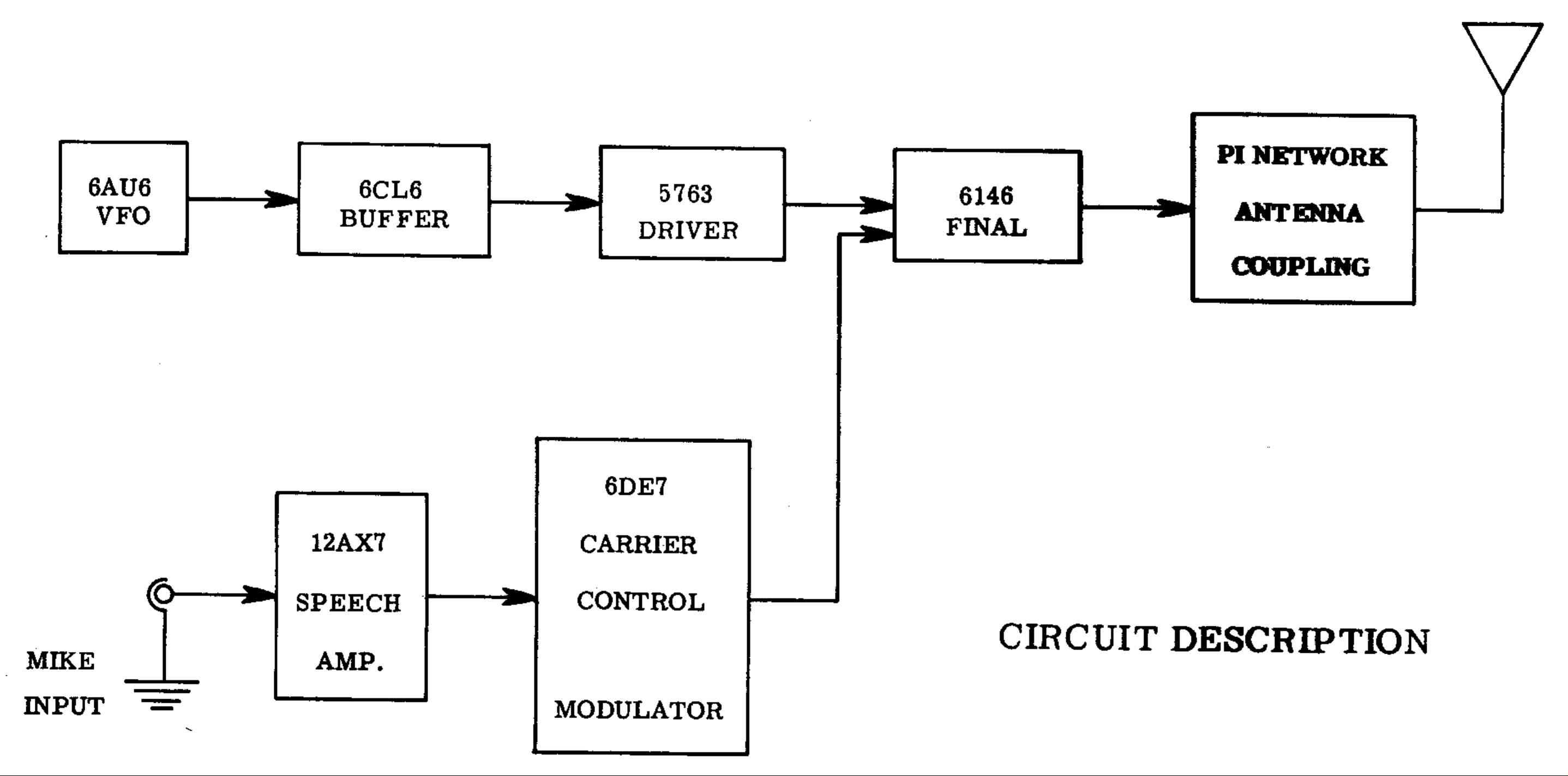
The MT-1 consists of a 6AU8 VFO, a 6CL6 buffer, a 5763 driver and a 6148
final amplifier. The modulator utilizes two dual triodes: a 12AX7 and a 6DE7.
The following block diagram and circuit description will serve to better
aquaint a builder with the operation of the Transmitter. This knowledge is
an invaluable aid to construction and, as such, is well worth reading
thoroughly. Lethal voltages are present at many points above and below the
chassis, consequently, great care must be exercised when any tests or
adjustments are made.
VFO
The VFO circuit consists of a 6AU8 tube operating as a Clapp oscillator in
the frequency ranges of 1750 to 2000 kc, 7000 to 7175 kc, and 7000 to 7425 kc.
The tube is mounted on to of the rigid enclosed chassis partition, thus
placing all heat generating components outside the VFO enclosure. A double
bearing ceramic insulated tuning capacitor is used as a frequency control.
The VFO tuning capacitor, consisting of two stator assemblies of different
capacities, permits a large bandspread at both high and low frequencies.
Pagina 1
Page 5

mt1
The coils are wound on heavy ceramic slug-tuned coil forms, heavily doped
and baked. The result is a high Q coil upon which varying ambient conditions
have a minimum effect. Careful placement of temperature compensating
capacitors near the coils tends to cancel drift due to coil heating.
In addition, a temperature compensating capacitor across the grid circuit of
the tube, carefully positioned physically, provides additional compensation
for other varying inductive parameters.
The VFO switch is operated by an interrupted switching mechanism on the band
switch. VFO output frequency is correlated with the band in use as follows:
80 meters - 1750 to 2000 kc; 40 meters - 7000 to 7425 kc; 20 meters - 7000 to
7175 kc; 15 meters - 7000 to 7175 kc; and 10 meters - 7000 to 7425 kc. This
unique switching system, coupled with the vernier slide rule full gear dial
drive mechanism, provides more than adequate frequency spread on all bands.
The Clapp or series tuned Colpitts oscillator circuit presents a very low
impedance to the tube grid at resonance. This minimizes the effect of shift
in tube capacitance upon the output frequency. The capacitive voltage divider,
necessary for operation of the Colpitts circuit, also lessens the effect of
tube capacitance upon frequency. Both screen and plate voltages are
stabilized by an OA2 regulator tube.
The untuned output circuit of the VFO operates at 80 meters when the 80-meter
band is used and at 40 meters when all other bands are used. This circuit
consists of the output coaxial cable capacitance, plus the RF choke in the
VFO plate circuit. The VFO output thus obtained insures more than adequate
drive on all bands. The output is fed to the 6CL6 buffer stage.
A 6CL6 tube is employed as a buffer stage to further isolate the oscillator
and, at the same time, insure adequate drive even under low battery conditions.
The plate circuit of the 6CL6 is untuned when operating 80 meters, slug-tuned
to 40 meters for operation at 40, 20 and 15 meters, and slug-tuned to 20
meters when operating 10 meters. An untuned RF choke and the two slug-tuned
coils are in series with the B+ lead to the 6CL6 plate. One section of the
exciter band switch shorts out the coils not being used for a given band.
The RF ground is provided by a large capacitor, since a direct ground would
short the B+ lead. The output of the 6CL6 is capacitively coupled to the 5763
driver stage.
Driver
A 5763 tube is employed as a driver for the 6146 final amplifier. This stage
utilizes series plate feed, and is capacitively coupled to the grid of the
final amplifier. The plate circuit consists of a tapped coil which is ganged
with the VFO and buffer band switch and is tuned by the front panel controlled
variable capacitor. The driver stage is keyed in the cathode circuit along
with the final amplifier for CW operation.
Final Amplifier
The plate circuit of the final amplifier is shunt fed with a 2.5 mh RF choke
and is capacity coupled into the pi network tank circuit. A tapped inductance
is used for tuning all bands and the tap is selected by the bandswitch.
In the 80-meter position, a 68 mmf 4 KV capacitor is automatically paralleled
with the plate tuning capacitor. The loading capacitor consists of a
three-gang, 450 mmf per section, variable capacitor with the sections in
parallel.
Modulator
The 12AX7 tube is used as a high-gain two stage resistance-coupled speech
amplifier. The output of the speech amplifier is coupled to the 6DE7 modulator
tube through a low capacity coupling capacitor. This low coupling capacity
serves in shaping the response to favor the voice frequencies, thus allowing
a higher average level to be maintained at frequencies where it will be
most effective.
Pagina 2
Page 6

mt1
The audio energy from the speech amplifier is coupled to the grid of one
triode section of a 6DE7. This tube contains two dissimilar triode sections:
one triode section is rated at 1.5 watts dissipation, and the other at 7 watts
dissipation. The lower rated triode is used as a direct coupled driver, its
plate being tied to the control grid of the heavier duty triode, which forms
the modulator. The heavy duty triode is biased sufficiently to limit its
conduction, and therefore the screen voltage on the final 6146 amplifier.
This results in a low resting carrier and, consequently, very low battery
drain.
With modulation, the conduction of the heavy duty triode section is varied
in accordance with the average voice level. This gives a controlled carrier
effect by varying the screen voltage on the 6146 tube, and at the same time,
the audio signal is superimposed. The net result is to produce a carrier
output which increases with the percentage of modulation applied.
Microphones
Since mobile operation demands that properly shaped audio response be
employed, a vary carefully designed ceramic microphone is included with the
MT-1 "Cheyenne" Mobile Transmitter. This is to insure very effective
modulation with plenty of "punch". The microphone serves to suppress all but
the upper middle range of the voice frequencies and the audio system, as
described above, is designed around this response. If other microphones are
used, it may be necessary to alter the circuit components and the modulator
for best results. In any case, the microphone should be a high impedance type
and preferably ceramic, since crystal or carbon microphones can be damaged by
the hot sun to which they are often subjected in mobile operation.
NOTE: IT SHOULD BE NOTED THAT AN AMATEUR RADIO OPERATOR AND STATlON
LICENSE IS REQUIRED TO PLACE THIS TRANSMITTER ON THE AIR. Information regarding
licensing and amateur frequency allocations may be had from publications of
the Federal Communications Commission or the American Radio Relay League.
( ) Supply the connection between W-4 and W-6 on the power socket as explained
in the note. This connection is needed only when the power supply is not
running continuously. If the power supply is controlled by its own switch,
then turn the B+ voltage on and ignore the previously mentioned connection.
CAUTION: Remember that potentially lethal voltages are present during the
following steps.
( ) Plug the microphone into its receptacle at this time.
( ) Turn the function switch to the STANDBY position and apply the B+ voltage
to power plug W on the rear apron of the chassis. NOTE: This voltage will
not be applied any further than the power plug until the microphone button
is depressed. The pilot lights and all tubes should be lit. If nothing
unusual is noted, then proceed with the following steps.
( ) Turn the function switch and the meter switch to the GRID position.
Depress the microphone button and adjust the driver tuning control until
a maximum reading is obtained. It will be noted that there is more than
one peak on the 10 and 15 meter bands, in which case the maximum peak is
used. When this peak has been found, drive may be reduced by slightly
detuning off this peak. Typical drive after loading should be near 3 ma.
Repeat this operation on all bands, 80 through 10 meters. The 10 and 15
meter drive may be slightly low until the buffer plate coils are peaked
in a later operation.
( ) Connect a dummy load, such as a 60 watt light bulb, to the coaxial output
jack at V. The band switch should be in the 80 meter position for this
check and the VFO set to some frequency known to be in the phone portion
of the band. Since the VFO has not yet been calibrated, it will be
necessary to check the signal on a receiver to determine that it is within
the phone portion of the band. Check for and obtain grid drive as
described above by depressing the microphone button and adjusting the
Pagina 3
Page 7

mt1
driver tuning, with the function switch and the meter switch in the GRID
position. Now, with the meter switch in the PLATE position, set the
loading control fully counterclockwise and the function switch to the
PHONE position. Depress the microphone button and tune the final tuning
control for a dip. The dip is first obtained in this position since less
current will be drawn here than in the CW position. Now that the resonant
point has been determined, move the function switch to the CW position.
Advance the loading control until a reading of 150 ma is obtained on the
meter in the PLATE position. Redip the final tuning control. Adjust the
grid drive, final tuning and the loading control until the Transmitter
is loaded to 150 ma. Try to reach this point in a minimum amount of time.
Now move the function switch back to the PHONE position. Advance the
audio gain control until peaks of 150 ma can be read on the meter when
speaking into the microphone. Do not exceed this point. A red line is
provided on the meter for quick observation of peaks.
In actual operatian, you will find some output indicating device such as the
Heathkit Mobile Tuning Meter an invaluable aid. If such a unit is available
to you, then the Transmitter may best be adjusted for maximum output in the
PHONE position by sustaining a tone and adjusting the final tuning, drive,
and the loading control. The point of maximum output may differ slightly
in this method than in the CW position and is considered as the best method
of tuning, since the Transmitter output power is being observed rather than
the input power. Peaks of 150 ma should not be exceeded in normal operation.
( ) Remove the microphone from its receptacle for the following VFO
calibration. Very small amounts of grid drive will be observed on the
meter under this condition, since only the oscillator is involved in
this operation.
VFO CALIBRATION
If the kit builder has access to a commercial frequency standard, an
electronic counter of good quality, a surplus frequency standard of the LM
or BC series, or a high quality communications receiver with a built-in
crystal calibrator, such as the Heathkit "Mohawk", these are excellent
for calibration. If a frequency meter is used, the frequency meter and the
VFO signals can be beat against each other in the receiver. It will be
necessary to calibrate only the 80, 20 and 10-meter bands. Since the 20 and
15-meter bands of the "Cheyenne" both use a common VFO switch position, as do
the 40 and 10-meter bands, when the 20 and l0-meter bands are calibrated, the
40 and 15-meter bands are also calibrated automatically. Before beginning
calibration, allow the Transmitter, frequency meter and the receiver to warm
up for one half hour or more. During the calibration procedure, the drive
control should be set at maximum grid current reading with the function and
meter switch in GRID position. The spotting switch should be set to its
ON position. If a frequency meter is used for calibration, the frequency
meter signal and the VFO signal should be zero beat against each other in a
receiver, with the BFO off. Under these conditions, the VFO is at the same
frequency as the frequency meter. Aside from slight differences in measurement
technique, the following procedure may be used for either method of
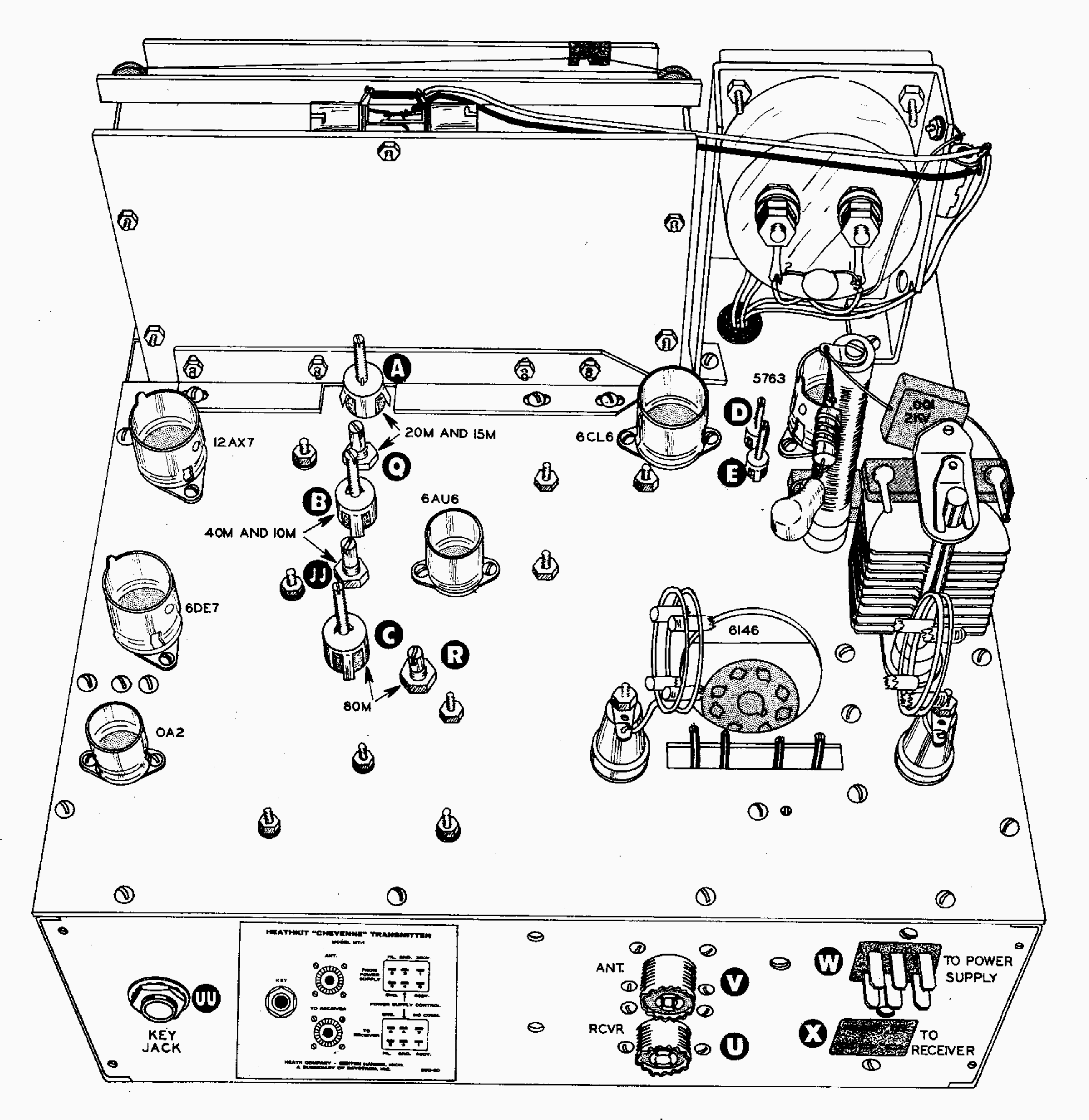
calibration. Refer to Figure 41 on page 45 for location and identification
of the various calibrating adjustments. If you should be unable to hear the
VFO signal in the receiver, a piece of hookup wire may be run near the
oscillator tube over to the receiver input terminal for better signal pickup.
NOTE: It should be noted that the trimmer capacitors R, Q and JJ are used to
determine the frequency spread covered on the dial, while the coil slugs A, B
and C in Figure 41 are used to set a definite frequency point in the dial.
The coil slugs are set to the calibration frequency at the low end of the
dial; the trimmers are adjusted so that the calibration frequency at the
high end of the band coincides with the dial reading. These two adjustments
interact with each other and, therefore, will have to be adjusted alternately
until optimum overall calibration is obtained. All the trimmer capacitors
should be set to HALF MESH, before starting calibration. Make sure the steps
regarding the setting of the main tuning capacitor and dial pointer, in
Pagina 4
Page 8

mt1
relation to the dial mechanism, were not overlooked or done improperly.
For 80-meter calibration, set the MT-1 dial at 3500 kc and set the frequency
meter without modulation, to the same frequency. Make sure the band switch is
in the 80-meter position. Adjust slug C for zero beat in the receiver. Note
that zero beat will result when the VFO frequency is the same as the 3500 kc
output of the frequency meter. Now, retune the VFO to the high end af the band
and move the frequency meter up to a frequency of 4000 kc. Reset the receiver
as in the previous step. Tune the VFO to zero beat at Lhe high end of the band
and note the reading. Starting with the trimmer R plates at HALF MESH, adjust
trimmer R until the VFO is zero beat on 4000 kc. Readjust slug C for zero beat
once again at the lower calibration frequency of 3500 kc. Move the VFO up and
check the high end, and it should be found that the dial reading is closer
to the actual frequency than before, Adjust trimmer R again and repeat this
process until calibration is achieved at both ends of the band. Repeat the
procedure outlined above for the 20 and 10-meter bands, moving the band switch
to the appropriate band for each calibration procedure. The receiver and
frequency meter, or signal sources, must operate between 14000 and 14350 kc
for the 20-meter calibration, and between 28000 and 29700 kc for the 10-meter
calibration. Use trimmer Q and slug A for the 20-meter calibration and trimmer
JJ and slug B for the 10-meter calibration. This will complete VFO
calibration. Be sure to remove any wire serving to couple the oscillator to
the receiver before proceeding.
( ) Now again insert the microphone plug into its receptacle, setting the
function switch to its PHONE position.
After VFO calibration is complete, the adjustment of the buffer coils may be
accomplished. Set the band switch to the 10-meter position and the VFO dial
to the middle of the band, approximately 28.8 mc. Depress the microphone
button, tuning the final to resonance and adjusting the loading to maximum
plate current. Advance the drive control until a small amount of grid current
reading can be obtained. Adjust slug D, as shown in Figure 41, for a maximum
grid current reading. Now switch the band switch to the 15-meter position and
set the VFO dial to the middle of the band or approximately 21.3 mc. Peak the
drive once again at a low reading and adjust slug E, Figure 41, for a maximum
reading on the meter. If 15 and 10-meter drive seems low, slightly spreading
the turns on the 10/15-meter drive coil will provide optimum drive. This
completes testing, adjustment and calibration of your MT-1 Mobile Transmitter.
( ) If CW operation is contemplated it is suggested a two wire cable be
brought out to an external SPST transmit-standby switch. The internal
connections of this cable are as follows: One wire to pin 4 on female
microphone socket Z, the other wire to pin 1. The function switch should,
of course, be in CW position for CW operation.
( ) Insert a phone plug into the key jack on the rear apron. B+ is turned ON
by throwing the transmit-standby switch to ON. The oscillator and buffer
will run continuously with the driver and final stages keyed in their
respective cathode leads. CAUTION: Approximately 90 volts will be present
at the key terminals under "key-up" conditions. A low voltage keying relay
could be used for greater safety if desired.
Pagina 5
Page 9

Page 10

 Loading...