

Heath Company Heathkit H9 Assembly Manual

,,'"..'t'.
.:.,r
::,
.
'
H
MANUAL
for the
VIDEO
ASSEMBLY
TERMINAL
Model
H9
5e5-1se6-05
\,
\
HEATH
COMPANY
.
BENTON
HARBOR,
MICHIGAN
HEATH
The following
Kit
orders
Credit.
ReplacementParts..
8:00 A.M. to 12
RZC, Audio,
Amateur
Test Equipment,
Home
Television
Aircraft,
Appliances
Computers
telephone numbers
and delivery information
Technical Asslstance
P.M. and 1:00
and Electronic
Radio
Weather Instruments
Clocks
Marine, Security,
and General Products
COMPANY PHONE DIRECTORY
are direct lines
Phone Numbers
P.M. to 4:30 P.M.,
Organs .
and
Scanners, Automotive,
to the
departments listed:
(616)
......
......(616)982-3561
(616)
..
EST, Weekdays
(616)
....
(616)
(616)
(616)
(616)
. . .. .
(616)
...
982-3411
982-9571
Only
982-3310
982-3296
e82-3315
982-3307
982-3496
982-3309
YOUR HEATHKIT
you
If
ae not satisfied with our sewice
Services, Heath Company, Benton Harbor, Michigan
attention.
Our attorney, who happens to be
phrases
in
order to comply with the new
period
For a
either in materials
telephoning us at
We wmrant that during
and used in accordance with
If
a defective
fault
Electronic
You will receive
drop us a
Our wananty does not cover and we ile not responsible
incomect
advertised. Our warranty does not include reimbursement
This
our
limitation
gives you
of ninety
part
yours,
we will
of
Center
line
or
assembly, misuse, fire, or by unauthorized modifications to or uses of our
warranty covers only Heathkit
products.
We are not responsible
incidental or consequential damages, so the above limitation or exclusion
of
specific
days after
[90)
workmanship. You can obtain
or
SB2-3571.
[616]
first ninety
the
in
or error
(units
free
give
legal rights,
design
service
of Schlumberger Products Corporation), or
consultation on any
us a call. Sorry, we cannot
warranty
-
quite
a kitbuilder himself,
wananty regulations. Fine. Here they are:
purchase,
And
we'll
(90)
days after
printed instructions, will meet
our
has
caused
it free
and
proof
upon
problem you
products
and
for
incidental or consequential darnages.
you
may also have
90
or otherwise - or
49022. He
Heath Company
parts
pay
shipping chmges
purchase,
your
Heathkit
purchase
of
might encounter
accept collect
is
not extended to
other
HEATH
BENTON HARBOR, MI. 49022
DAY LIMITED
products,
with our
will make certain
insists
that we describe our
will replace
from
directly
our
product
and
delivery
calls.
for
damage caused
for
customer assembly or set-up
rights which
COMPANY
or
Heath Companyby
get
to
those
products,
published
to malfunction during the wailanty
at
any
our authorized overseas distributors.
of
in the
allied
equipment
vary from
WARRANTY
write directly to our Director of Custoner
your problems
repair free of chmge any
parts
when correctly assembled, calibrated,
specifications.
your
expense to the Heath
assembly
by the use
or components used in conjunction
Some states do not allow the exclusion or
state
receive immediate,
warranty using all the necessary
parts
miting us at the address below or by
you
to
- anywhere
your
or use of
corrosive
of
products
may
for
time.
not apply
to
state.
that are defective
in the world.
period
factory,
Heathkit
solder,
purposes
you.
to
defective tools,
other than as
This waranty
ffirdtffbTbTbllThtllK
personal
adiusted
through no
Heathkit
any
product.
legal
|ust
with
d5
o<J
-ir
.fJ
=-
Prices
and specifications
subject to
change without notice.
Heathkit@
for the
Manual
VIDEO TERMINAL
Model H9
ASSEMBLY
5e5-1ee6-05
HEATH COMPANY
BENTON
HARBOR,
MICHIGAN
49o
22
Printed
Copyrlght
Heath
Nl Rights Reserved
in the
Uniled States of
1977
@
Company
America
Pase.
@
INTRODUCTION.
UNPACKING
CHASSIS
Partslist
Assembly
Step-by-StepAssembly
POWER
Parts List
Assembly
Step-by-Step Assembly
Power
CHARACTER GENERATOR
Parts
List
Step-by-Step Assembly
Character Generator Circuit
Board
VIDEO
CIRCUIT
Parts
List
Step-by-Step
Video
.. ..
Notes
SUPPLY
Supply
Checkout
Circuit Board
CIRCUIT
Notes .
Checkout
BOARD
Assembly
BOARD
Checkout
TABLE
CIRCUIT
BOARD
OF
.....5
... . . 8
...71,
33
36
38
46
52
54
61
62
64
73
CONTENTS
KEYBOARD
Partslist
Step-by-Step Assembly ...
Keyboard
RAM AND
Partslist
Step-by-Step Assembly .. 105
Ram
Board
INPUT/OUTPUT
Partslist
Step-by-StepAssembly ..119
I/O
Circuit Board
TIMING
CIRCUIT
Partslist
TPU
ADIUSTMENTS .
FINAL
WARRANTY
CIRCUIT
Circuit
COUNTER CIRCUIT
and Counter Circuit
Checkout .. 1.12
AND PROCESSING
BOARD
Circuit
ASSEMBLY
Board
.... .. Inside front
BOARD
Board
CIRCUIT
Checkout
Checkout
Checkout . .... 99
BOARD
BOARD
UNIT
....85
87
...103
...1.17
.. . . 728
...732
... 734
't37
...
....... 139
cover
CRT Installation
.
75
CUSTOMER SERVICE ....
Inside rear
cover
L@
-
INTRODUCTION
Page3
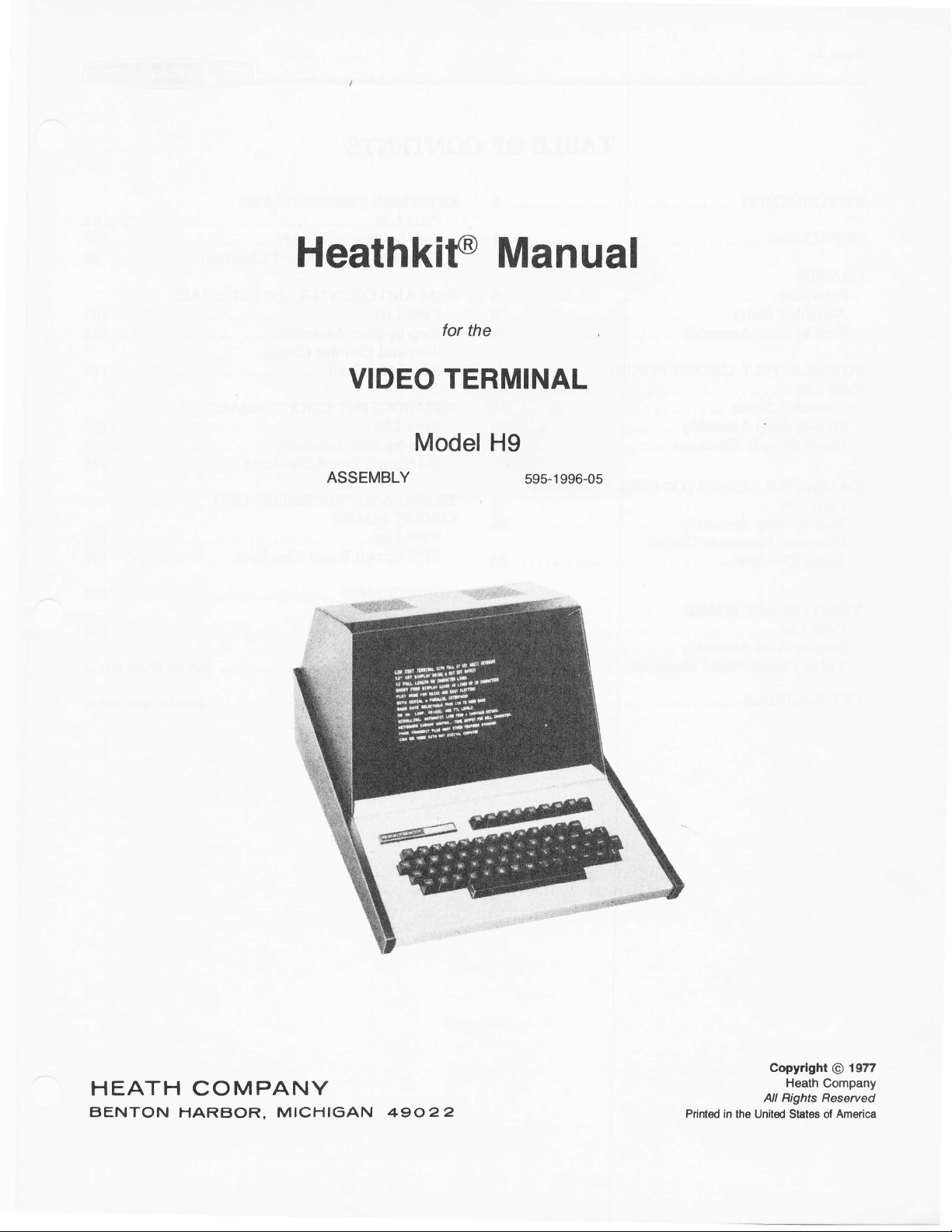
The Heathkit
information
mation into
72"
ort a
capable of displaying 960
rows
with 80 characters
A sixty-seven
compose
bility
of
This message or
tions.
ted through
TTL,
or
through the
punch.
The Video Terminal
computer in dedicated, stand-alone
in
time-sharing systems.
with a digital computer
such as Basic, Assembler, etc.,
machine language. The Video Terminal is also
(up
faster
mechanical teleprinter systems. You can select any
rate
data
Model H9
coming from a computer or enter
a computer.
(diagonal)
key ASCII keyboard
and edit
64 different
the standard serial
mA
20
current
parallel I/O interface to a
to 9600 baud) than the standard electro-
between 110 and
Video
The information is displayed
cathode
directly
characters and
program
loop) to a digital computer
can
Terminal can display
ray
characters at
per
row.
onto
be used with any digital
It lets
in higher-level
9600
(CRT)
tube
one
permits you
the CRT with
24 different
can then
I/O interface
applications, or
you
communicate
rather
baud.
infor-
which is
in 12
time
a capa-
func-
be transmit-
[EIA,
paper
than
tape
languages,
just
in
much
to
or
important features
Other
o
Automatic
a
Cursor
o
Erase
.
Erase
o
Short form
characters).
o
Automatic line
o
Plot
o
Built-in
These features,
cabinet, make the Video Terminal a
peripheral
controls.
to end of line.
page.
mode.
speaker
along
your
to
include:
scrolling.
(four
12-line
carryover.
(audible
with
computer system.
bellJ.
the attractively-styled
columns
very versatile
of
2O
TJNPACKING
Inside
"PKS 1-6,"
remove
parts
ray
Remove
cathode ray
called for in
cathode
so in a
sonal
When
find a Pack Index
the shipping
and a
the box
will
tube is separate
the
ray
step. Improper
injury
you
stamped PKS 1-6,
be considered the "final
box stamped
tube
a Parts List.
tube carton
or tube
open the box stamped PKS 1-6,
carton there is a box
number
in its
carton and
until
unpacking
damage.
Sheet
loose
of
pack."
own shipping
PKS
1-6-
set it
WARNING:
you
are instructed
can result
in the top
all the
of
stamped
parts.
After
remaining
The
cathode
carton.
Remove
aside until
Do not
open the
in
you
the box. This
you
it is
to
per-
will
the
do
sheet shows
ent compartments
as "packs." You will be directed
"packs"
be
removed from the boxes or
until they are specifically called for by a
the
Manual.
Each
assembly
"Parts
tions.
be instructed
be directed,
parts
from
how
it is needed.
as
List"
and "Step-by-Step
At
the beginning
to open
in
the final
box has
the
which are referred to
section
one of the
some Parts Lists,
pack.
been
CAUTION:
of the Manual
of each
divided into differ-
in
to
open each
No
their
compartments
contains
Assembly" instruc-
"Parts
List,"
packs.
You
to remove
Manual
the
of these
parts
should
Parts List in
its
own
you
will
will also
certain
r@
-
CHASSIS
Page5
Unpack the following
check each
key numbers
sis Parts
part
Any
with a
envelope
step.
NOTE:
your
than
used
way if
Some
aging number.
and do not appear
only
packaging
all
cated.
To
order a replacement part,
PART
with
this kit
Order Form
part
against
correspond
Pictorial
that is
part
after it is identified
You should
work area.
until later in
placed
parts
NUMBER.
(Illustration
packaged
number
are marked with a "77L-" or
or at
is not
on
place
Many
the assembly
your
on
These
numbers are
material until all
Use the Parts
the rear
available, refer
parts
from
the final
following
the
to the numbers
Booklet,
in
individual
an
it should
the
of
work area.
in
the
of this Manual. If
placed
be
until it is
parts
in a location
parts
these
and will be in
used for
Manual Parts List. Save
parts
always
Form furnished
Order
to "Replacement
PARTS
pack
and
Parts List. The
on the
Pages 1 and 2).
called
"172-"
have been lo-
include
Chas-
envelope
back in
will
packaging
the
for
in a
other
not
be
your
pack-
the
a Parts
LIST
Parts"
the front
Parts Price
Each
ponent
number
of these
ever has to
the
numbers
inside
cover. For
circuit
Number
for
numbers,
same
part
will
In
At
ponent
In
In
In
rear
the
List."
component in
only that
be replaced,
in
appeal
the Parts
the
some illustrations.
the
the
cover.
prices,
(R2,
which
each section
beginning
is installed.
Schematic.
sections at the
C4,
one
is
List.
refer
this kit
Q1,
part
are
to help
Warranty
Your
to the separate
has a
etc.). This is a
in the kit. The purpose
especially
you
of the
of each
step where
rear
of
is inside
"Heath
Circuit
specific
useful if
easily identify
Manual. These
the
Manual.
Com-
part
a
a com-
IMPORTANT: The TPU
during the 90-day
Center.
warranty. DO
voids
It will be
the warranty.
period,
NOT
promptly
attempt
circuit
board assembly has been wired and tested at
return the complete circuit board assembly to
repaired and
to service this circuit board assembly
returned. Individual replacement
yourself
Heath
during
Heath
Company.
Company or
parts
are not
the warranty
If it malfunctions
a Heathkit Electronic
supplied under
period;
to do so
Paseo
KEY
HEATH
No.
Part No.
DESCRIPTION
QTY.
CIRCUIT
Comp. No.
KEY
No.
HEATH
Part
No.
DESCRIPTION
QTY.
@
CIRCUIT
Comp. No.
CIRCUIT
A1
A1 6-15'l
A2
M 21-17
A3 25-810
A4
A5
A6
A7
A8
A9 56-26
A9
A10
All 401-163
COMPONENTS
6470-12
2't-96
25-156
25-822
51-194
g-943
58-8
56-56
60-2
1
1
1
1
'l
1
1
1
2
1
A,
47
1|4-watl
violet-black) resistor
O,
150
green-brown)
pF
36
ceramic capacitor
pF
270
pF
500
capacitor
pF
4000
capacitor
12,@O
capacitor
Flyback
Power transformer
Deflection
1N191
white-brown)
1N4149 diode
Slide switch
Speaker
(yellow-
1/2-waft
ceramic capacitor
electrolytic
y"F
diode
(brown-
resistor
electrolytic
electrolytic
transformer
yoke
(brown-
WARNING: Do not remove the cathode ray tube
carton
A1z
NOTE: A
the following
you
until
41 1-830
instructed
are
1 310GJB4
tube
to do so
cathode
ray
in
a step.
transistor can be marked for identification in
four ways:
1. Part number.
2. Type number.
3. Part number
4. Part
number with a type number
and type number.
other than the
listed.
A13
414
417-894
421-23
1 BU180A
transistor
1 l-ampere,3AG,
slow- Fl
blow fuse
INSULATORS
81 73-92
82
73-132
73-23
83 75-30
84 75-52
85 75-728
86 75-734
75-124
87 75-704
1
314' x 5" foam
1
1
1 Line
'l
'12
4
1 4-112'
rubber
Small
Large rubber
cord strain relief
Slide switch insulator
Circuit board standoff
Circuit board holder
x
grommet
grommel
d'fish
tape
paper
1 Transistor insulator
R'l
c5
@
c3
c2
c1
T2
T1
L1
D2
D1
SW1, SW2
SPKRl
from its
CRTl
one of
one
01
CONNECTORS
c1 432-866
_
15
c2 432-753 15
c3 432-855
u 432-9il
c5
432-970
c6 432-821
c7
432-183
432-924
c9
432-951
c10
38
1
2
1
1
|
1
c1l 432-832 13
HARDWARE
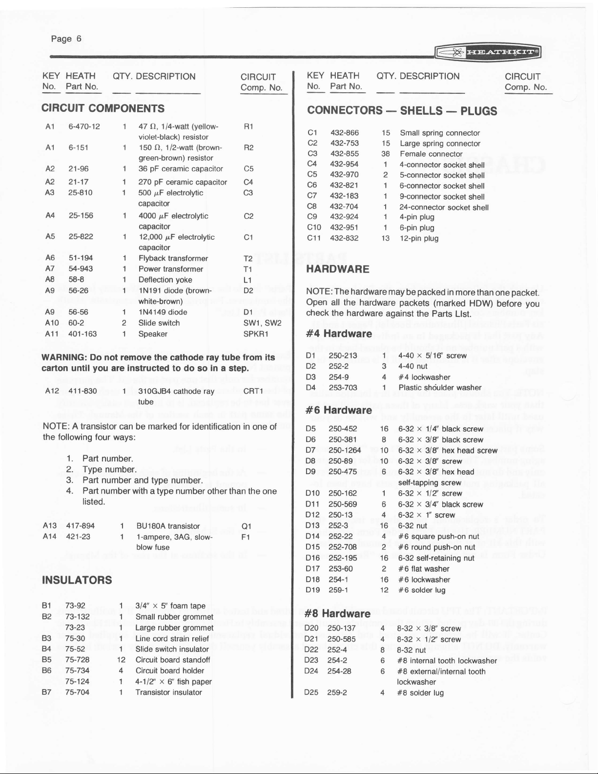
NOTE:
The
hardware
Open
all the hardware
check
the hardware
against
#4 Hardware
D1 250-213 1
D2 252-2 3
D3
2U-9
4
D4 253-703 1
Hardware
#6
D5
250-4s2 16
D6 250-381
D7
250-1264 10
D8
250-89 10
D9 2fi-475
D10 2fi-162
D11 250-569
D12 250-13
D13 252-3
I
6
1
6
4
16
D14 252-22 4
D15 252-708
2
D16 252-195 16
D17 253-60
D18
2*-1 16
D19
259-1 12
2
#8 Hardware
D20
250-137 4
D21
250-585 4
D22
D23
D24
D25
2524
2V-2
2*-28
259-2
8
6
6
SHELLS
Small spring connector
Large spring connector
Female
4-conneclor
s-connector
6-connector
g-connector
24-connector
4-pin
6-pin
12-pin
may
be
packets
connector
socket
socket shell
socket
socket
plug
plug
plug
packed
(marked
-
socket
in
the Parts
x
4-40
5/16'screw
440
nut
#4 lockwasher
Plastic
shciulder
x
114'
6-32
6-32 x 3/8'
6-32
6-32 x 3/8'screw
6-32 x 318'
self-tapping screw
6-32 x 1/Z
6-32 x 3l4i
6-32
5-32 nut
#6 square
#6 round
6-32 self-retaining nut
#6 flat washer
#6 lockwasher
#6
solder
8-32
8-32
8-32 nut
#8 internal
#8
externaUinternal tooth
lockwasher
#8
solder lug
black screw
black screw
x
hex head
3/8'
hex
screw
black screw
x
1"
screw
push-on
push-on
lug
x
3/8" screw
x
1/2'screw
tooth lockwasher
PLUGS
shell
shell
shell
shell
more than
HDW)
Ltst.
washer
screw
head
nut
nut
packet.
one
before
you
KEY
No.
HEATH
Part No.
DESCRIPTION
QTY.
CIRCUIT
No.
Comp.
KEY HEATH OTY. DESCRIPTION
No. Part
No.
CIRCUIT
Comp.
No.
LINE
CORD
CABLE-
89-54
134-1001 1
134-1002 1
134-1009 1
134-1016 1
340-8
344-15 z',
344-59
344-94 3g'
347-1 8',
346-1 12',
HARNESSES - WIRE
-
SLEEVING
1
10',
10',
METAL PARTS
E1 204-2325 2
204-135 2
E2
E3 206-1247 1
E4 206-1248 1
E5 203-1886-1
E6 204-2324 1
E7 207-86 1
E8 207-63 1
E9 200-1321 1
E10 203-1887-1 1
203-1885-1
E11
|
1
MISCELLANEOUS
Line cord
Main harness
Bus harness
2'l
-wire
8-wire
Bare wire
Black wire
White wire
Yellow
8-wire cable
Sleeving
brace
CRT
Angle bracket
High voltage top
High voltage bottom shield
panel
Rear
CRT bracket
Capacitor clamp
Capacitor strap
Chassis
Front
Bottom
cable
cable
wire
panel
panel
assembly
assembly
shield
1
(cont'd.)
4
Alligator
1
Cabinet
consisting of:
set
Left side
1
Right side
't
Screwdriver
2
6
4
1
6
1
2
'l
1
1
1
I
1
1
1
'1
1
1
1
spring
Coil
Tension spring
Rubber
Silicone
Cable tie
voltage
High
Chassis
Model label
Model label holder
Fuse holder
terminal strip
3-lug
s-lug terminal strip
Cabinet window
Magnitying
Plastic nut starter
De-solder wick
Integrated circuit
puller
(lC)
Wrench
Blue and white
Parts
Order
clip
panel
side
(#203-1889)
(#203-1890)
blade
foot
grease
label
plug
label
glass
(braid)
label
Form
-
Miscellaneous
F2 260-16
203-1894
F3
F4
205-778
F5
F6 258-33
258'79
F7
F8 261-21
F9
352-13
F10
3y-7
390-147
390-1382
F11
390-1387
F12
391-61
F13
423jt1
F14
431-604
F15
431-42
446-686
406-664
Fl6
490-5
490-1
85
F17
490-189
Fl8
490-168
391-34
597-260
F1
74-6
90-'t2't0-1
181-2679-2
I
Roll masking tape
Cabinet shell
1
Assembled timing and
1
processing
circuit board
unit
(TPU)
Solder
1
Manual
for
1
lllustration
1
Operation
Page 1 for
part
(See
Page
number.)
Booklet
Manual
part
number.)
1
(See
Pases
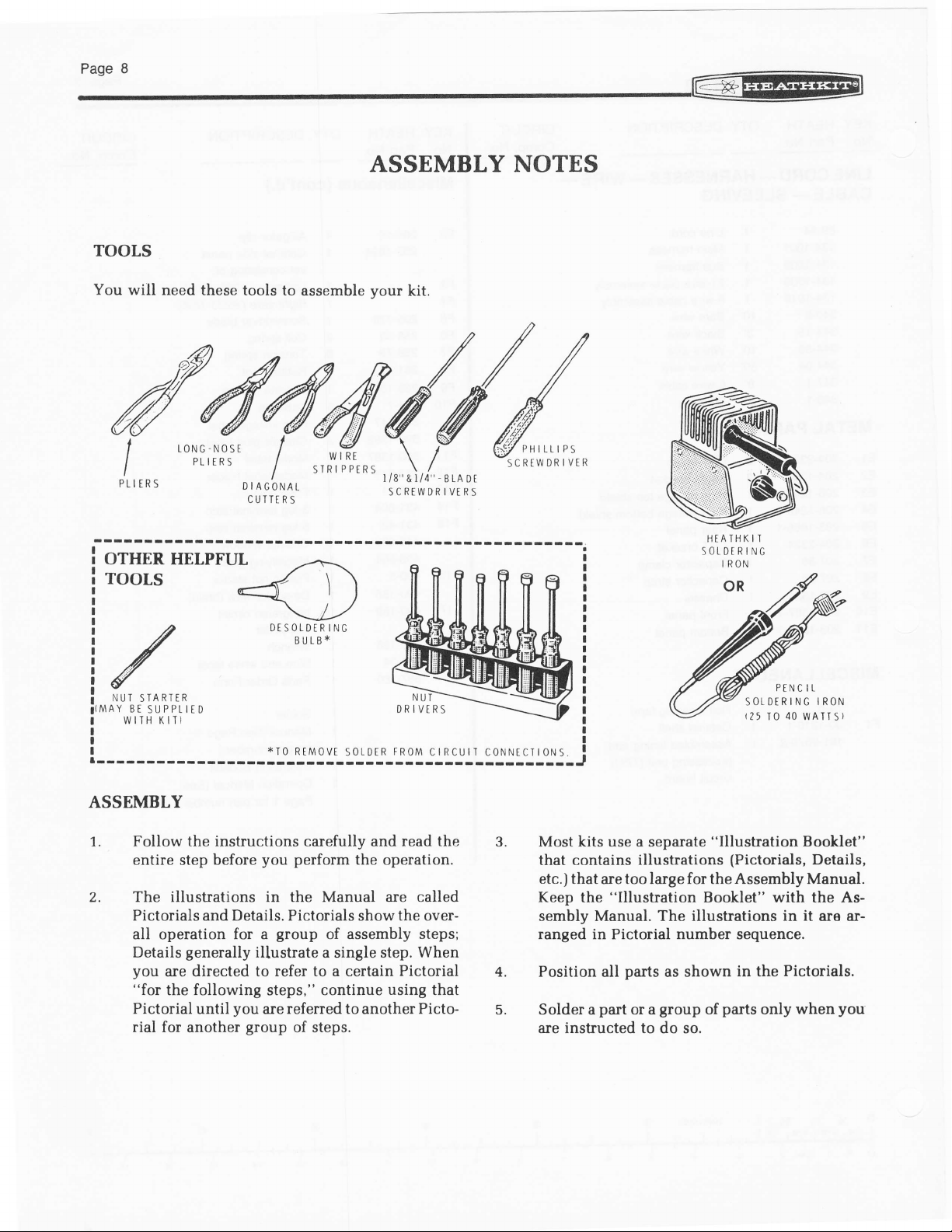
TOOLS
@
ASSEMBLY NOTES
You will
need these tools to
I
I
I
PLIERS
LONG.NOSE
PL IT R
OTHER HELPFUL
root,s
ilur
!
1{MAY
I
sTARTtR
Bt
SUPPtItD
WIIH
KIT}
assemble
I
S
I
I
DIAGONAT
CUTTTRS
--+.
4 \ )
\,
DiSOLDTRING
EIJLBT
WIRT
STRIPPIRS
kit.
vour
@
l
l/8"&r/4'
SCRTWD
I
4''-BLADT
DRIVTRS
PHILLIPS
SCREWDRIVTR
PtNC
10
40
tr
wATTS)
SOTDERING
125
IRON
ASSEMBLY
Follow the
entire
The
2.
illustrations
Pictorials
all operation for a
Details
you
are directed to
"for
the following steps," continue
Pictorial until
rial for
instructions
step before
Details. Pictorials
and
generally
you
another
Sroup
*I0
RtM0vt
carefully
you perform
in the
group
Manual
of assembly
illustrate a
s0LDtR
single
FR0M
ctRcutT c0NNEcTt0NS
and read the
the operation.
are called
the
show
over-
steps;
step. When
refer to a certain Pictorial
using
that
are referred to another Picto-
of steps.
I
-----J
3.1,
Most kits use a
that contains
etc.)
that are too large for the Assembly Manual.
Keep
the
sembly Manual. The
separate
illustrations
"Illustration
"Illustration
Booklet" with the As-
illustrations in it
ranged in Pictorial number sequence.
part
parts
group
or a
to do so.
as shown
of
4.
J.
Position all
Solder a
instructed
are
(Pictorials,
in the
parts
Pictorials.
only when
Booklet"
Details,
are ar-
you
r@
-
Page9
part
Each circuit
6,
component
numbers
part
These numbers, which are especially
part
7.
When
particular
vided
SAFETY WARNING: Avoid eye iniury when
excess
off
fly toward
when
in the various sections
has to
In
the
At
the beginning
component
In some illustrations.
In the
In the
you
at the bottom
lead lengths. Hold the leads so they cannot
your
in an electronic
number
be replaced, appear:
Parts
Schematic,
section at
are instructed to cut something to a
length,
eyes.
(R2,
C4, etc.).
you
want to identify the same
List,
of each step
is installed,
the rear
the
use
scales
of the Manual
has
kit
Use these
of the
useful if a
the
of
(rulers) pro-
pages.
its own
Manual.
where a
Manual.
you
cut
SOLDERING
Soldering
will
der connection
tween two
terminal strip
prevent
ing
It is
follow a few
1. Use
2. Keep the
is
perform
an otherwise
properly.
easy to
the right type of soldering
40-watt
3/16" chisel or
wet
on a
the tip to
process
tip
and
When
the tip, the tip needs to be
ned.
the
one of
assembling
while
form
will
parts,
such as
lug. A bad solder connection
make a
simple
pencil
soldering
sponge or cloth; then
give
is called tinning,
enable
solder tends to
good
and
could
operat-
if
25
etick
retin-
you
sol-
you
the
most important operations
your
kit. A
an electrical
a component
well-assembled kit
good
solder connection
rules:
soldering
pyramid
the entire tip a wet look. This
you
tip
iron
tip clean. Wipe it often
make
to
"ball"
connection
lead
from
iron. A
iron with a 1/8" or
works best.
apply solder to
protect
it will
and
good
connections.
or does not
cleaned and
be-
a
to
to
Paselo
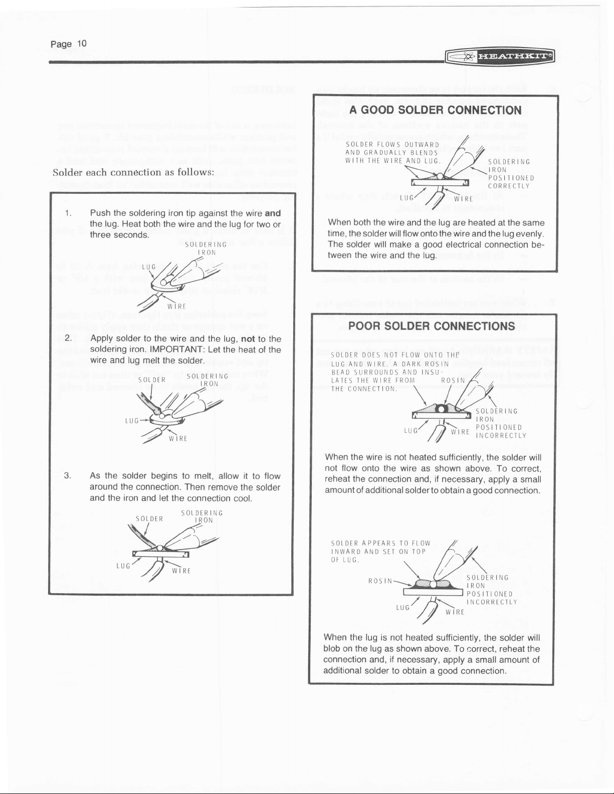
A
GOOD SOLDER
@
CONNECTION
Solder each
1.
Push the
the lug.
three
2.
Apply
soldering iron.
wire
connection
soldering
Heat
both
seconds.
solder to
IMPORTANT:
lug
and
melt
follows:
as
iron
tip
against
the
wire and the lug lor two
SOTDERING
IRON
wire
the
and the lug,
Let
the solder.
the
wire and
not to the
the heat
or
of the
SOtDER
AND
WITH
When
time,
The
solder will make
tween
SOTDER
LUG
BEAD SURROUNDS
TATIS
THI CONNECTION
FLOWS
GRADUALLY
THT WIRI AND
both the wire
the solder will flow
the wire
POOR
ANO
THt
and
SOLDER
DOTS NOI
WIRT. A DARK
W I RI FROM
OUIWARD
BLENDS
LUG.
,ur/
and the
onto
good
a
the lug.
FLOW
oNTo rHe
ROSIN
AND
INSU
SOLDERING
IRON
POSITIONiD
CORRTCILY
lug
heated
are
the
wire and the lug
at the same
evenly.
electrical connection
CONNECTIONS
ROSIN
SOLDERING
IRON
POSITIONED
wlRE
iuConnEcriv
be-
3.
As
the
solder begins to melt,
around
the
connection. Then remove
and the iron
and
let
the
connection cool.
SOLDtRING
allow it
the solder
to
flow
When the wire is
not
flow
onto the wire as
reheat
the
amount
When
blob
of additional solder to
INWARD
LUG.
APPTARS
SOtDIR
OF
the lug is not heated
the lug
on
not heated
sufficiently, the
shown above.
connection and, if necessary,
obtain a
FLOW
SIT
IO
ON TOP
AND
ROS IN
sufficiently, the solder will
as shown above. To
connection and, if necessary,
additional
solder
to
obtain a
good
solder will
To
correct,
apply a small
good
connection.
ING
R
s0tD
IRON
POSITIONED
INCORRECTLY
correct,
reheat
the
apply a small amount
connection.
of
@
t"n"tt
STANDOFF
INSULATOR
STEP.BY.STEP
NUT
DR IVER
o*
ll
pusH
oowni
?
, r*$'Jl,(,*
CARTFULLY
WORK
INSULATOR
INTO
/
HOLE
ASSEMBLY
@o
druu
r'rur
iz
LocKWAsHER
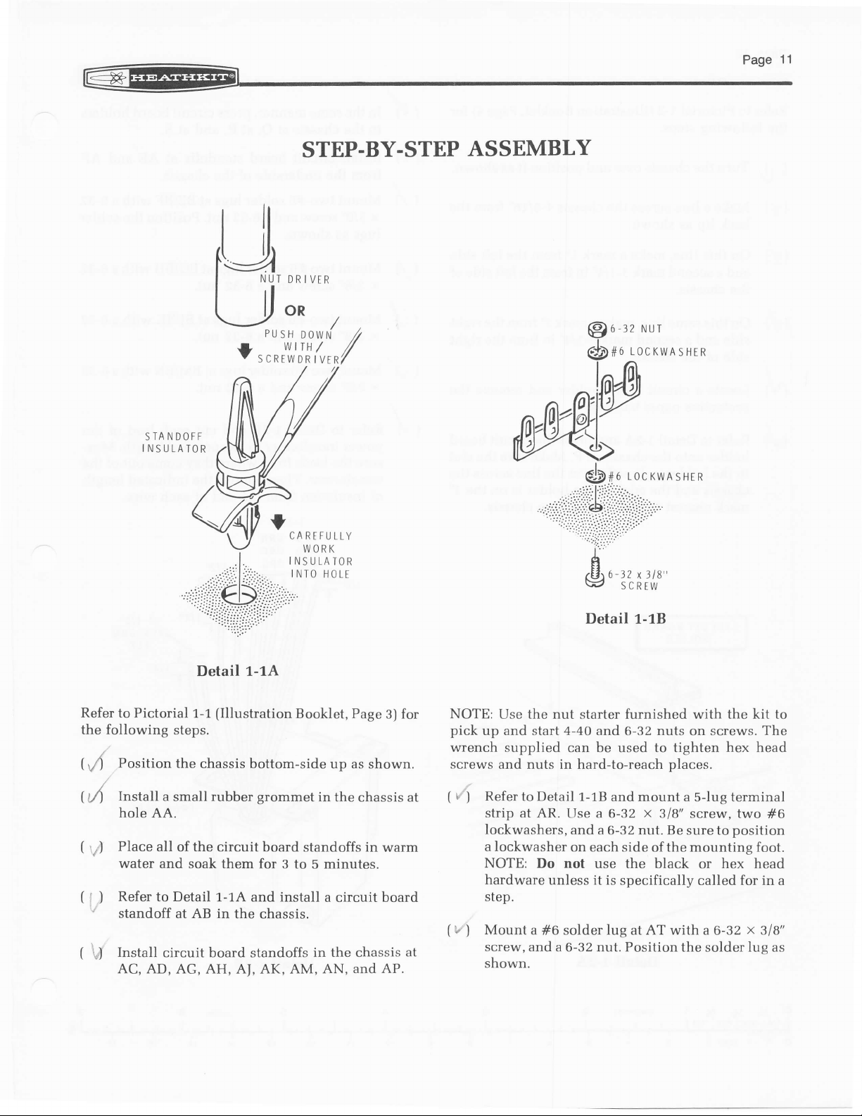
Refer
Pictorial
to
the following
(rA
Position
(A
Install
hole AA.
(
Place all
rf)
water
(
Refer
)
I
''
(
U
to
standoff at AB in
Install
AC, AD, AG,
Detail
1-1
1-1A
(Illustration
Booklet, Page
steps.
the chassis bottom-side
a small
rubber grommet
of the circuit board
and soak them for 3
Detail
1-1A
and
to 5 minutes.
install
the chassis.
circuit board
AH,
standoffs
AJ, AK,
AM,
for
3)
up as shown.
in the
chassis at
standoffs in warm
a
circuit
in the chassis
AN,
board
at
and AP.
Detail t-tB
NOTE:
pick
wrench supplied
screws and nuts in hard-to-reach
( ,/)
(i"
Use the nut starter furnished with the kit to
up and
Refer
strip at AR.
lockwashers,
a lockwasher
NOTE:
hardware
step.
Mount a
)
screw, and
shown.
4-40 and
start
can be used to tighten
to Detail
1-18 and mount a
Use a 6-32 x 318'
and
on each
Do not use
unless it is
#6 solder
a 6-32 nut. Position the
6-32
a 6-32 nut. Be sure to
side of the mounting foot.
the
specifically called for in
lug
at
black
AT
nuts
on screws.
places.
5-lug terminal
screw, two
or
with a 6-32
solder
The
hex head
position
hex
head
x
3lB"
lug
#6
a
as
Refer
the
f
(
r"
(',
(U)
\/)
(
(;,
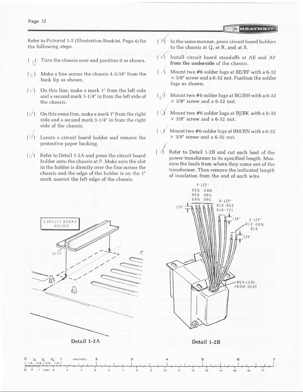
Pictorial 1-2
to
following
Turn
fJ
)
)
)
the chassis
Make a line across the chassis 4-511,6'from the
back lip
On this line, make
and a second mark
the
chassis.
this
On
side
side
Locate
protective paper
Refer to Detail
holder onto the chassis
in the holder is
chassis and the
mark nearest the left
same
and a second mark 3-1/4" in
of the chassis.
a circuit board holder
CIRCUIT
HOLDER
(Illustration
steps.
over and
as shown.
line,
backing.
1-2A and
directly over the line across
edge of the
BOARD
Booklet,
position
a mark 1" from the left
3-1,14'in from the left
make a mark 1" from
from the rieht
and
press
the circuit board
P.
at
Make sure the
holder is
edge of the
Page
it as
shown.
side of
the right
remove
on
chassis.
for
4)
side
the
slot
the
the 1."
(
In
4
to
(
Install
4
from
(
,
Mount
)
x
lugs
(,/)
Mount
'
x
('l
Mount
x
(
Mounttwo#6
d'
x
(
Refer
4
power
sure the
transformer.
of insulation
the same manner,
the chassis
circuit
the underside
two
3/8"
screw and a
as
two
3/8'screw
two
318"
screw and
318"
screw and
to
transformer
at
Q,
board standoffs at AE and
solder
#6
shown.
solder lugs
#6
and a 6-32 nut.
solder lugs
#6
a 6-32 nut.
solderlugsatBM/BNwitha6-32
a
Detail 1-28
leads from
Then remove
from
-112',
5
RID
GRN
RTD
ORG
6RN
0RG
6-32 nut. Position
to
where
the end
press
circuit board holders
at R,
and at S.
of the chassis.
lugs at BE/BF
BG/BH
at
at BI/gf
6-32 nut.
and
cut each lead
its
specified length.
they
come
the indicated
of
each wire.
4_rlT,
BLK-RED
BLK-YEL
l-
|14"
/"[r3^'
Ll4"
AF
with a 6-32
the solder
with a 6-32
with a 6-32
of the
Mea-
out of the
length
3-rl2',
Detail
1-2A
nr
Nt[.
-/
Detail
1-28
5
MEASURE
FROM HERE
S tOTS
LARGI SPRING
CONNECTOR
INSET
IX
S
CONNECTOR
SOCKTT
RED
PUSH
IN ON
TAB OF
SPRING CLIP
CRIMP OVER BARE
OF LEAD
TND
@:_
COOLED,
(
Refer
1
spring
transformer
not
solder the
that it
( Vl
Check
the connection is
have
is
tion
SOLDER
AFTER
AND
END OF
INSULATION
\
CLIP
HAS
BEND
INSULATION
OVIR
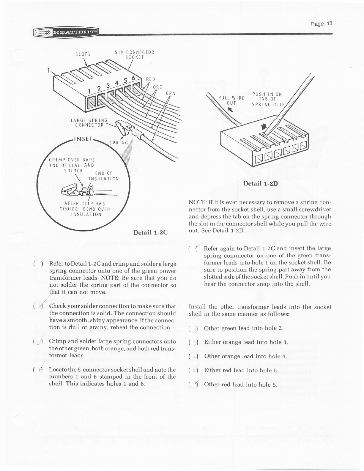
to Detail 1-2C and
connector onto one
leads. NOTE:
spring
can not move.
your
solder
connection to make sure that
solid.
a smooth,
dull
shiny appearance. If
grainy,
or
Detail
r-2C
crimp and solder a large
green power
the
of
Be sure that
part
9f
The
connection
the
you
connector
should
the connec-
reheat
the
connection.
do
so
'BEE
Detail
NOTE:
nector from the socket shell, use a small screwdriver
and
the
out. See Detail 1-2D.
(
Install
shell in the
(
If it
is ever necessary to
depress the tab on the spring connector through
in
slot
the connector shell while
Refer again to
4
spring
former leads
sure to
slotted side of the socket
hear the connector snap
Other
,)
connnector on one of
position
the
other transformer
same manner
green lead
Detail 1-2C and
into hole 1 on the socket
1-2D
remove
the spring
shell. Push
into the shell.
leads into
as follows:
into hole
you pull
insert the
the
part
2.
away
a spring con-
the wire
large
green
transshell. Be
from the
in until
the socket
you
Crimp and solder Iarge
tyl
other
green,
the
former leads.
( ,,4
Locate
the 6-connector socket
numbers 1
shell. This indicates
spring
both
orange, and both red trans-
connectors onto
shell and note the
and 6 stamped in the front
holes 1 and
6.
of
the
(
Either
i.l
(
,
Other orange lead
)
(
;)
Either
(
Other
\
orange lead into
into hole
red lead
red
into hole
lead into
hole
hole 3.
4.
5.
6.
Page
14
K;fi
^M
8-32
SCREW
x
318"
Detail
1-3A
6-32
BLACK
SCREW
x
ll4"
(
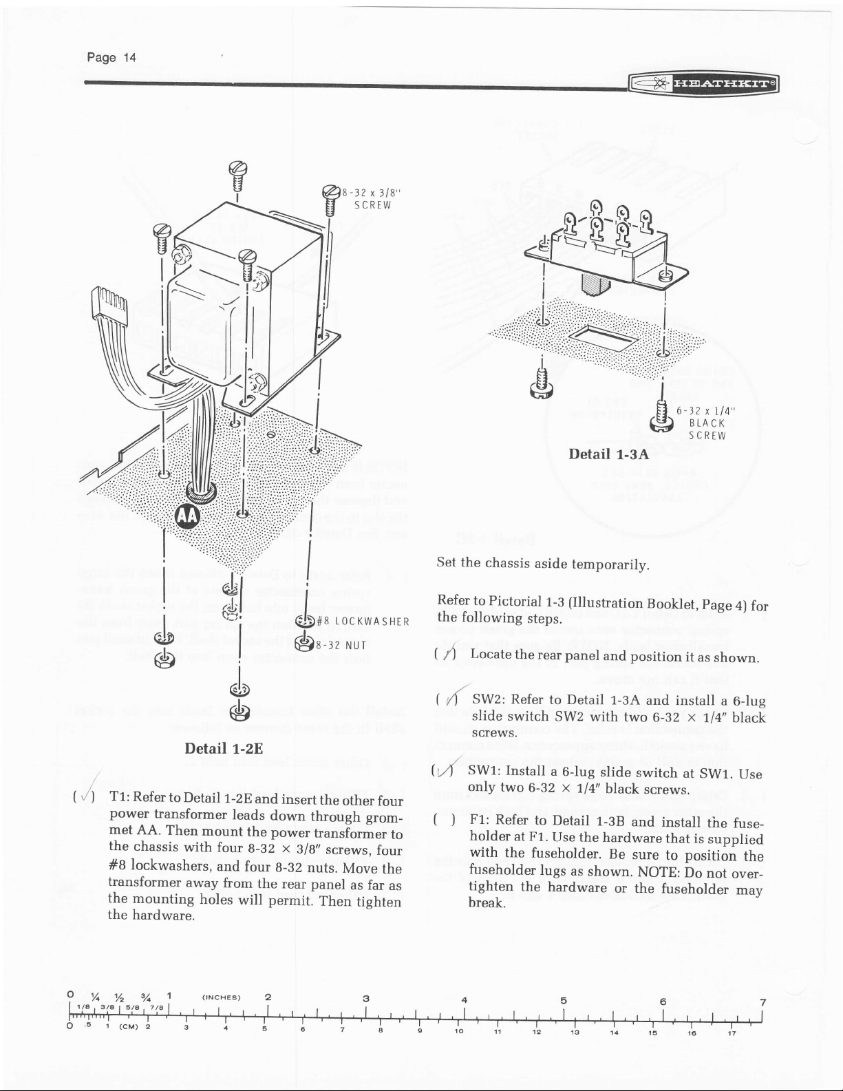
/)
T1:
Refer
power
met
AA.
the
chassis
#B lockwashers,
transformer
the
mounting
the
hardware.
.t
o
Detail 1-28
to
Detail
transformer
Then
mount
with
four
and
away
holes
1-2E
and
leads
down
the power
g-32
four
from
the rear panel
permit.
will
@)a-lz
insert
x
3/g,,
g-32
Nur
the
other
through
transformer
nuts.
Then
grom_
screws,
Move
as far
tighten
four
to
four
the
as
Set
Refer
the
(
I
1 4f
h,4
(
)
the
chassis
to
Pictorial
following
Locate
slide
screws.
SW1:
only
F1:
holder
with
fuseholder
tighten
break.
SWz:
two
Refer
Refer
switch
Install
the
the rear panel
at F1.
aside
temporarily.
1-3 (Illustration
steps.
to Detail
SW2
a
6-lug
x
6-32
to
fuseholder.
the
1/+"
Detail
Use
the hardware
lugs
as
hardware
and
1-3A
with
two 6-32
slide
black
1-3B
Be
shown.
or the
Booklet,
position
and
switch
screws.
and
install
that
sure
to
NOTE:
fuseholder
page
it
as
install
x
1/4" black
at
SW1.
the fuse-
is
supplied
position
Do
not
4)
for
shown.
a 6-lug
Use
the
over_
mav
3/A
6r(cv)z
3/t
%
7lA
I
(rNcHES)
1
@
t"n"tu
NUT
RUBBTR
WA SHER
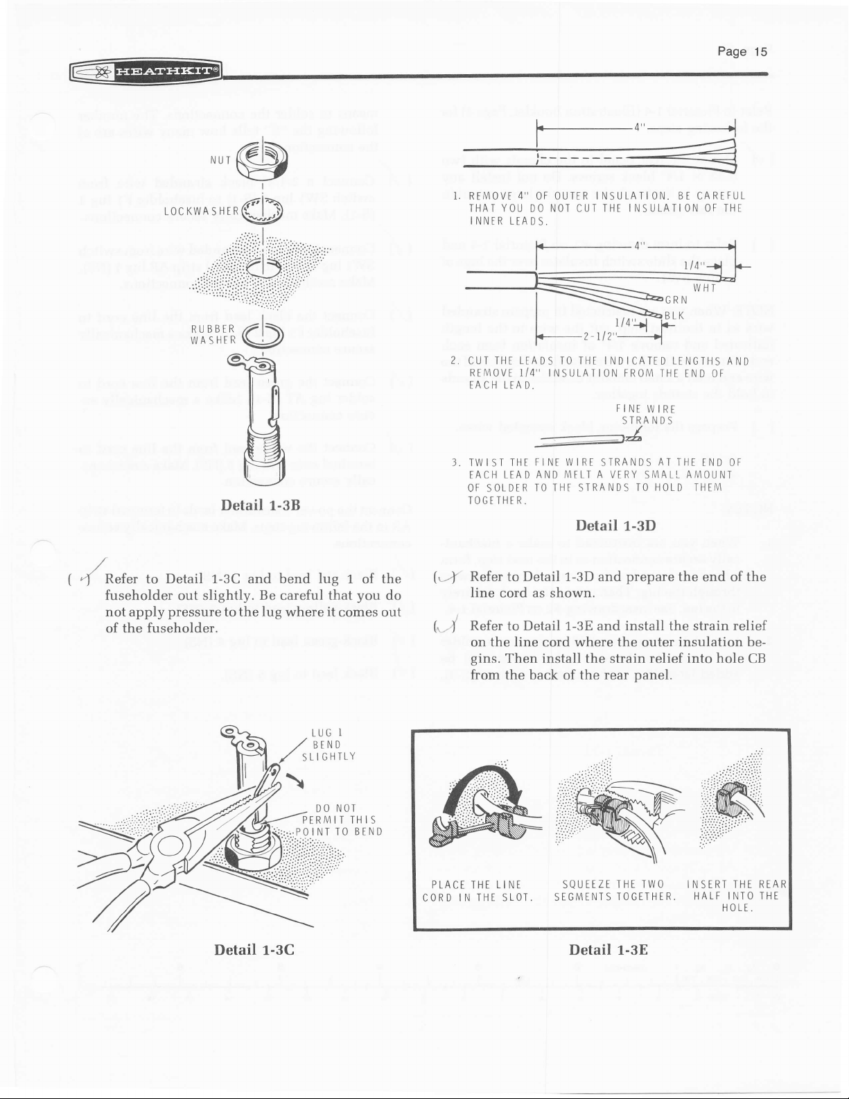
Detail 1-38
Xefer to Detail 1-3C and bend
{
fuseholder
not apply
of the
out slightly.
pressure
fuseholder.
to the lug where
Be
careful that
lug
1 of the
it
comes out
you
do
REIVI OVE
IHAI YOU
INNER LEADS.
CUT IHT
RTMOVE I/4" INSULATION
TACH LFA
3, TW I ST
EACH LEAD
OF SOTDER
TOGETHER.
(4
Refer
4"
OF OUTER
DO
LEADS
D.
FI
THE
AND
TO THF STRA
Detail 1-3D
to
NOT
NE W I RE STRANDS
I
NSULATION. BE CARFFL-
IHE I NSULATI ON OF IHE
CUT
TO THE INDICAIED LENGTHS
MFLT A
Detail
FROM
THE END OF
FINT
WIRE
S TRA N D
VERY
NDS TO HOLD THEM
S
AT
THE TND
SMAL!.
1-3D
prepare
and
the end of the
line cord as shown.
(..1
Refer to Detail 1-3E and install the strain relief
on the line cord where the outer
gins.
Then install the strain relief into
from
the back of the rear
panel.
insulation be-
AND
OF
AMOUNT
hole
CB
Detail t-eC
I
LUG
BEND
.IGHTLY
NOT
I TH
TO BEND
IS
PLACT
CORD
THT
I N THE
LINE
SLOT,
SQUEEZE
SEGMENTS
THE TWO
TOGETHER.
Detail L-3E
INSERT THE
HALF I NTO
HOLE.
REAR
THE
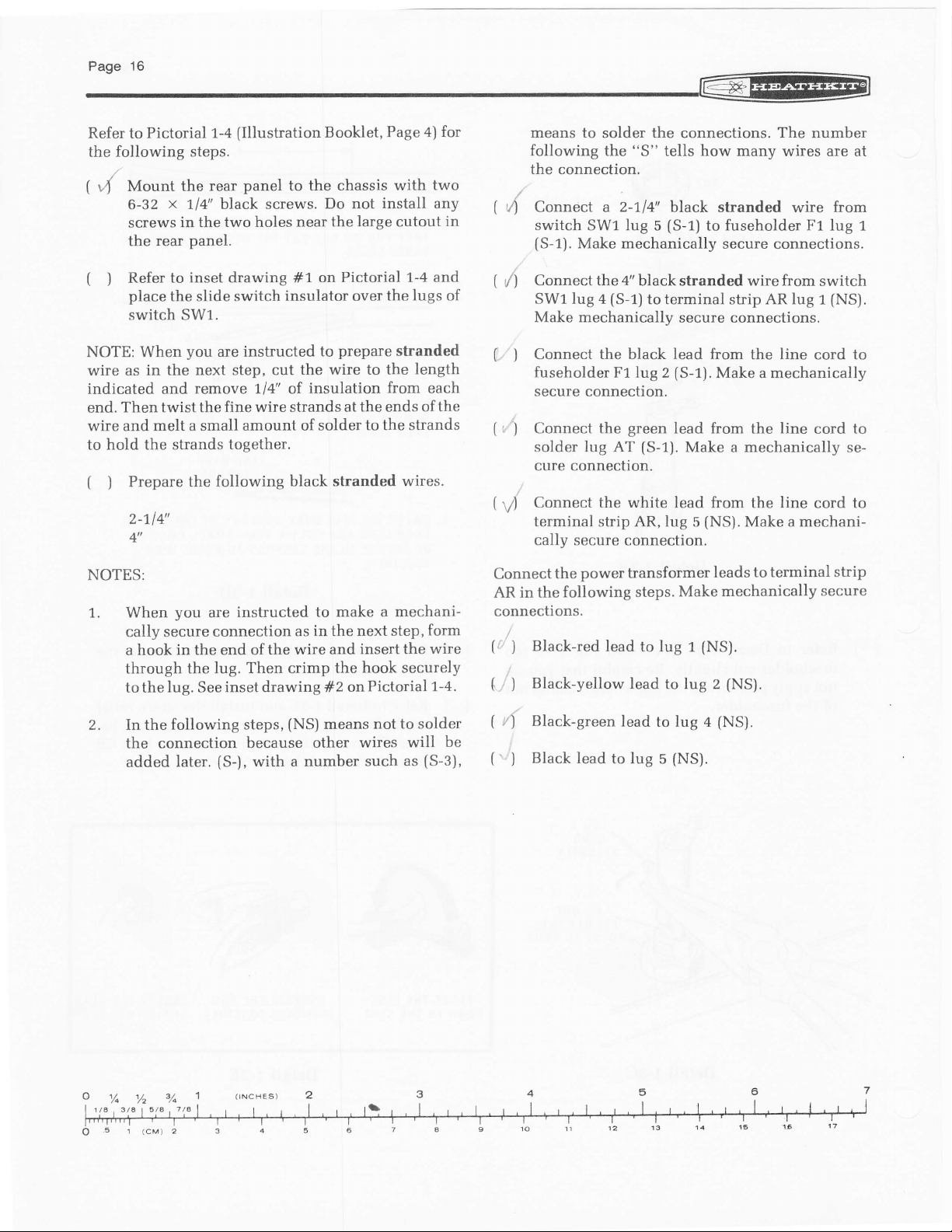
Refer to Pictorial
following steps.
the
(
Mount the
,4
x
6-32
screws
the
1/4" black screws.
in the
panel.
rear
(Illustration
1-4
panel
rear
two holes
Booklet,
to the
chassis with
Do not
near the large cutout
Page
install any
4)
two
for
in
means to
following the
the connection.
(
Connect a 2-114x
'/)
switch
(S-1).
Make mechanically
solder the connections. The number
"S"
SW1 lug 5
how many
tells
black stranded wire from
(S-1)
fuseholder F1
to
secure connections.
wires are at
lug
1
(
Refer to
I
place
switch SW1.
NOTE: When
wire
as
indicated and
Then twist the
end.
wire and melt a small
hold the strands
to
(
Prepare
)
2_\14'
4"
NOTES:
1,. When
cally secure
hook in the end of
a
through the lug. Then
to the
2. In the following
the
added
inset drawing #1. on
the slide switch
you
are instructed
in the
next step, cut the
remove 714' of
fine wire strands at
together.
the following black
you
are
connection
lug.
connection
later.
inset drawing #2
See
{S-),
insulator over
to
insulation
amount of
instructed to
the wire and
steps,
because other
with
solder to the strands
in
as
crimp the
(NS)
means
a number
stranded
length
from
each
of
form
wire
(S-3),
and
Pictorial 1-4
the lugs of
prepare
wire to the
the
ends
stranded wires.
make a mechani-
next step,
the
insert the
hook securely
Pictorial t-4.
on
not to solder
wires will
such as
the
be
(
Connect
t/)
SW1 lug 4
Make mechanically
(
Connect the black lead from
)
fuseholder
secure connection.
')
(,
Connect the
solder
cure connection.
(
Connect the white
r,/)
terminal
cally secure
Connect
AR in the
connections.
(r
,
(
(
rJ
('
the
following
Black-red
)
Black-yellow
)
Black-green
Black lead
)
4"
the
black stranded wire from
(S-1)
to terminal strip AR lug r
F1 lug 2
green
lug
power
(S-1).
AT
strip AR,lug 5
connection.
transformer
steps.
lead
to
lead
lead
to lug s
secure connections.
line
the
(S-1).
Make a mechanically
lead from
Make a mechanically
lead from the
(NS).
leads
Make mechanically
(NS).
lug
1
to lug 2
to lug a
(NS).
(NS).
(NS).
line
the
line
Make a mechani-
to terminal
switch
(NS).
cord to
cord to
se-
to
cord
strip
secure
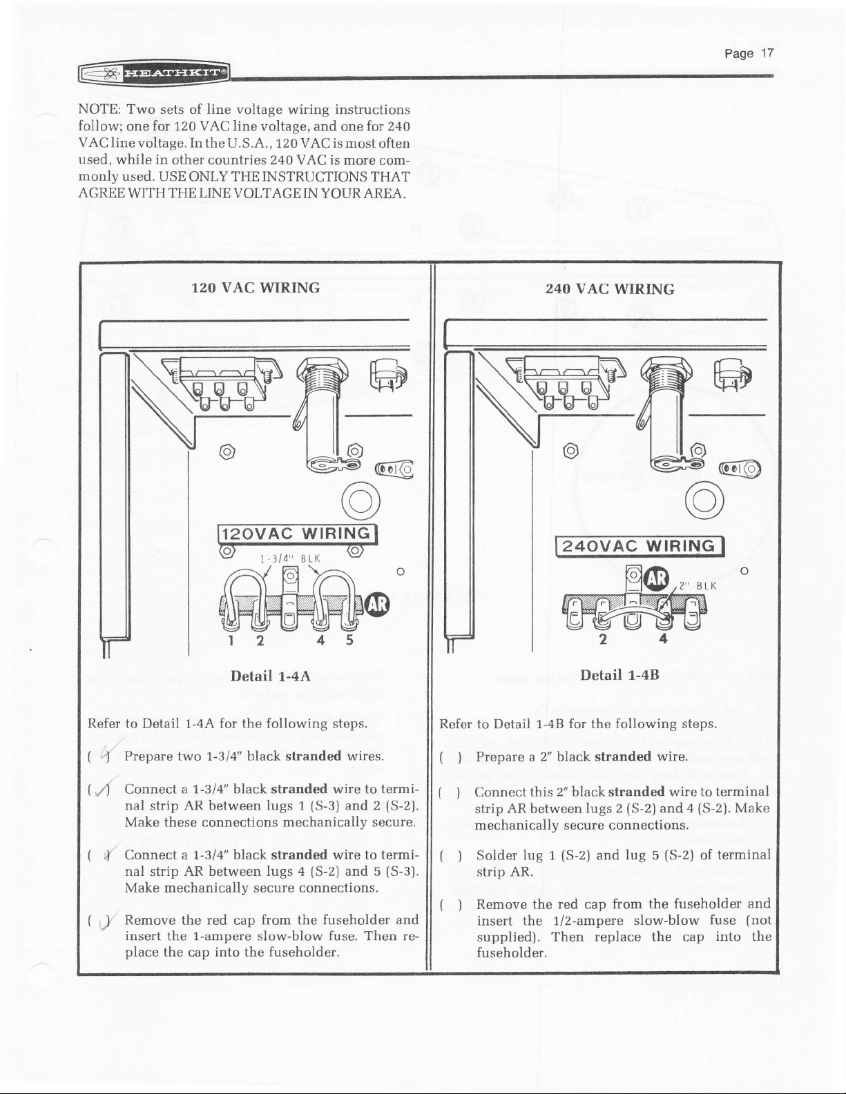
NOTE:
follow;
VAC
used,
monly
AGREE
Two sets
one
line voltage. In
while in
used. USE ONLY THE INSTRUCTIONS
WITH THE
line voltage
of
wiring
for 120 VAC line voltage,
the U.S.A., 120 VAC is
other countries 24OVAC is
LINE VOLTAGE IN YOUR AREA.
instructions
and one
most often
more com-
for 240
THAT
120 VAC
Detail r-+A
WIRING
24O
VAC
WIRING
24oV A,C W|RING
Detail
1-48
Refer to Detail 1-4A for the
(
"f
(
A
Prepare
Connect
two 1,-314" black stranded wires.
a 1.-314" black stranded wire to termi-
nal strip AR between lugs 1
(
J'
Make these
Connect a
nal
strip
connections
7-314'black
AR between lugs 4
following steps.
(S-3)
mechanically secure.
stranded
wire to termi-
(S-2)
Make mechanically secure connections.
(
,,)'
Remove
the
red
from the fuseholder and
cap
insert the 1-ampere slow-blow fuse. Then replace
the cap into the
fuseholder.
and 2
and 5
(S-2).
(S-3).
Refer to Detail 1-48
Prepare a 2" black stranded
t )
Connect
f )
strip
mechanically
(
Solder
)
strip
(
Remove the
)
this 2" black stranded
AR between lugs
secure
(S-2)
lug 1
AR.
red
for
following steps.
the
connections.
and
from the
cap
insert the 1/2-ampere slow-blow
supplied). Then
replace the cap
fuseholder.
(S-2)
2
lug
wire.
wire to terminal
(S-2).
a
and
(S-2)
5
terminal
of
fuseholder and
fuse
into
Make
(not
the
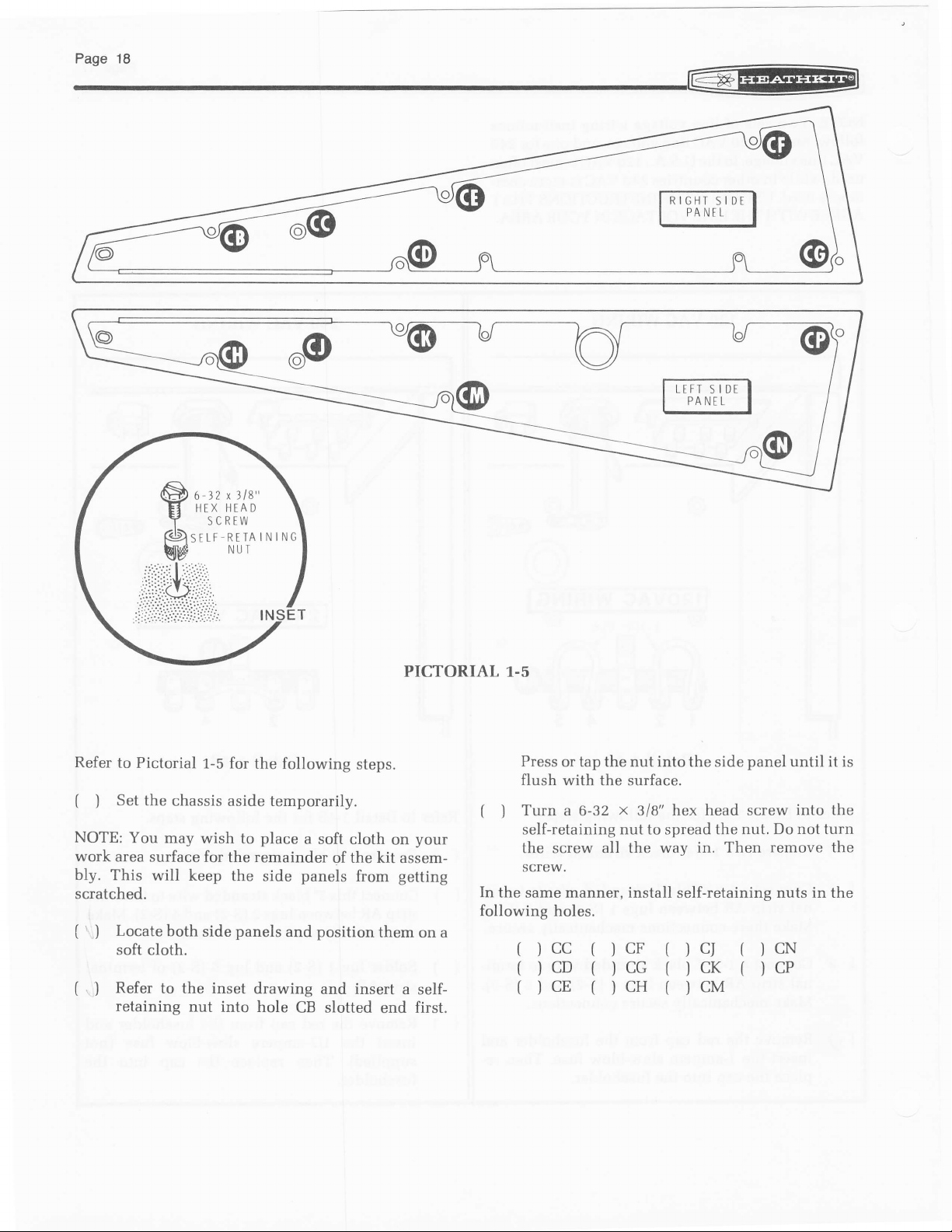
PICTORIAL 1.5
Refer
to Pictorial
(
Set the
)
NOTE;
work
bly.
scratched.
(
( .
This
'
)
l
You may
area
Locate
soft
Refer
retaining
1-5
for the following
chassis aside temporarily.
wish
surface for
will keep
both
side
cloth.
to the inset
nut
place
to
remainder
the
the
side
panels
drawing
into hole
panels
and
CB slotted
steps.
a soft
cloth
of the kit
from
position
and insert
on
assem-
getting
them
a self-
end
your
on a
first.
Press
or tap the nut into the side
flush with the surface.
Turn a 6-32 x 3/8" hex
t )
self-retaining nut to spread the nut.
the screw all the
screw.
In the
same manner, install self-retaining nuts in the
following holes.
CC
CD
CE
wav in. Then
CF
CG
CH
cI
cK
CM
panel
head screw
(
(
until it is
into the
Do not turn
remove the
)cN
)cP
@
6-jL
ry?-'ry
\
0
.g
6-32 x
I]EX
SCRTW
318"
HTA
Page
19
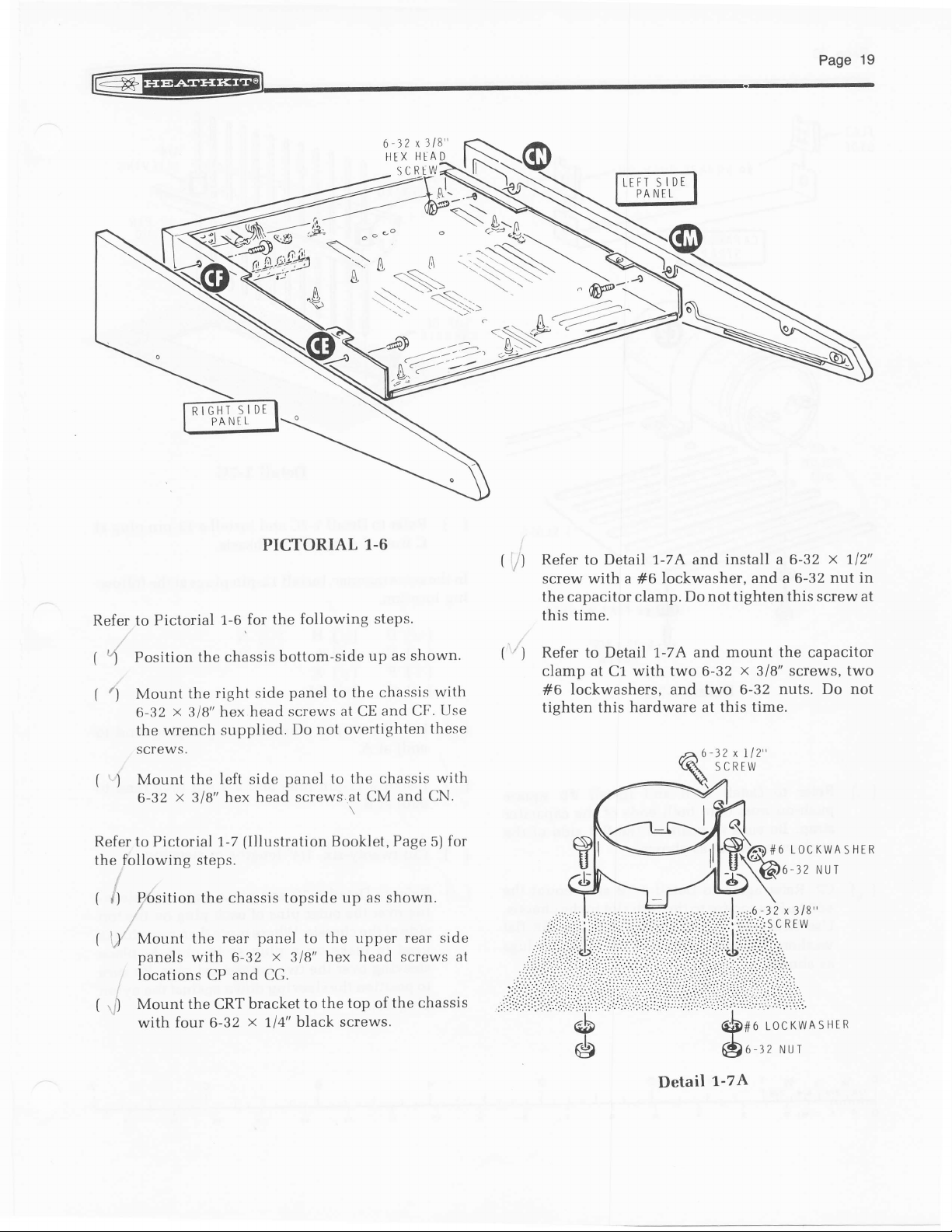
Refer to
(
\
(
(
Refer to Pictorial 1-7
the following steps.
f
(
Pictorial
Position the
t)
Mount
6-32 x 3/B"
wrench
the
SCTE\^/S.
Mount
)
6-32
P7bsition
it
i/
Mount the
panels
locations CP and CG.
1-6,for
chassis
right side
the
hex head
supplied.
the left side
x
hex
3/8"
the chassis topside up
rear
with
PICTORIAL
the
bottom-side
panel
screws
Do
panel
head screws
(lllustration
panel
x
6-32
3/8"
1.6
following
not overtighten
to the upper
hex head screws at
steps.
up as shown.
chassis
to the
at
and CF.
CE
the chassis
to
at CM
Booklet, Page
and UN.
as shown.
rear side
with
Use
these
with
for
5)
('
Refer to Detail 1-7A and
t)
(
')
with a
screw
the capacitor clamp.
this time.
Refer to Detail 1-7A and
clamp at C1 with two 6-32
lockwashers, and two 6-32 nuts.
#6
tighten
#6
this hardware at this
install a 6-32
lockwasher. and
Do not tighten this screw
mount the
a 6-32 nut
x
318" screws, two
time.
LOCKWASHER
-32
x
112"
in
at
capacitor
Do not
NUT
(
Mount the CRT bracket
';J
with four 6-32
x
to
black screws.
1/4"
the top of
the chassis
Detail
1-74
LOCKWASHER
#6
6-32 NUI
Pase2o
@
FLAT
IDE
S
6
g
fl
fl
SQUARE
#6
PUSH.ON
FLAT
IDE
S
rl4"
SLEEVING
il
ilt-
'lll-
ill-
-tl
il
Detail
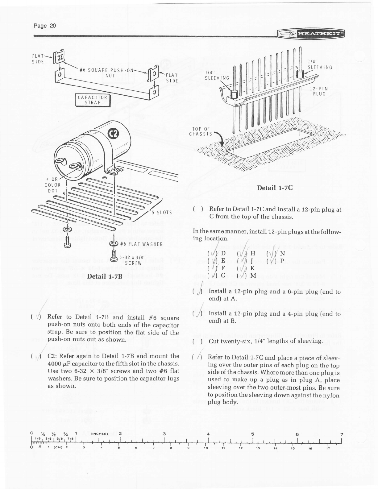
(
Refer
)
In
I
FLAT
6ou
wA'HER
the
ing location.
$'rt*;*'
Detail
t-zB
i
(
",')
to Detail
from
C
same
manner, install
//r
(t/)
D
(vfln
v/
F
t
(/)
G
Install
end) at
a
the top
A.
1-7C
of the chassis.
('l)
H
(/lI
(r'',)
r
(,/)
M
12-pin plug
t-zC
and install
12-pin plugs
(rlJ'
N
(/)P
and
a 6-pin
1l 4"
SLEEVING
l2-PtN
PLUG
12-pin
a
at the follow-
plug
fend
plug
at
to
(
Refer
r)
push-on
strap. Be
push-on
()
C2: Refer again to Detail 1-7B and mount the
4000
Use
washers. Be
as
to
Detail
nuts
onto
sure
to
nuts
out as
pcF
capacitor
two 6-32 x 3/8"
sure to
shown.
1-7B
and
both
position
shown.
to the
screws
position
ends
the
fifth
install
of the
flat
in
slot
and two
the
capacitor
#6
souare
capacitor
side
of the
the chassis.
flat
#6
lugs
(
Install
,l)
end) at B.
(
Cut twenty-six,1l4"
)
(
Refer
i
ing
side
used
sleeving
to
plug
a 12-pin plug
to
over the
of the
to make
position
body.
Detail
1-7C
and
pins
outer
chassis. Where
up a plug
over the
the
two
sleeving
and a 4-pin
place
of
each
more
as in
down
of
a
plug
than
against
lengths
outer-most
plug (end
sleeving.
piece
of sleev-
on the
plug
one
plug
A, place
pins.
Be
the
to
top
is
sure
nylon
r@
-
OF
NtI
LABET
MBER
SHTET
Page.1
S
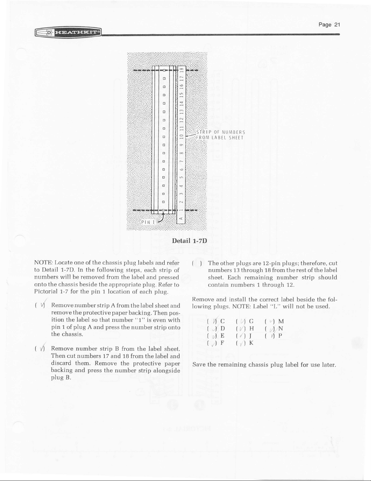
NOTE: Locate
to Detail
numbers will
onto the
Pictorial
(
v)
RemovenumberstripAfromthelabel
remove
ition
pin
the
(
\4
Remove
Then
discard them,
backing
plug
one
the
of
chassis
In
1-7D.
chassis beside the
1.-7 for the
the label
1 of
chassis.
cut numbers
B.
the following
removed
be
pin
protective
the
so that number
plug
A
and
number
Remove the protective paper
press
and
1 location
press
strip B from
1,7 and 18 from
the number
plug
from the label
appropriate
paper
the
labels and refer
steps,
each strip
pressed
and
plug.
Refer
of each
backing. Then
"l."
number
plug.
sheetand
is even with
strip onto
the label
the label and
strip alongside
Detail
of
to
pos-
sheet.
1-7D
(
The
)
numbers 13 through 1B from the rest
sheet. Each remaining
contain numbers 1 through 12.
Remove
lowing
and install
plugs.
fic
,.)
r)E
,)F
Save the remaining
plugs
other
NOTE: Label "L" will
D
are 12-pin
the correct label beside the fol-
(.)
G
(,,).
H
(
T
K
chassis
4P
plug
plugs;
therefore, cut
the label
of
number strip should
be used.
not
M
N
label for use later.
Page
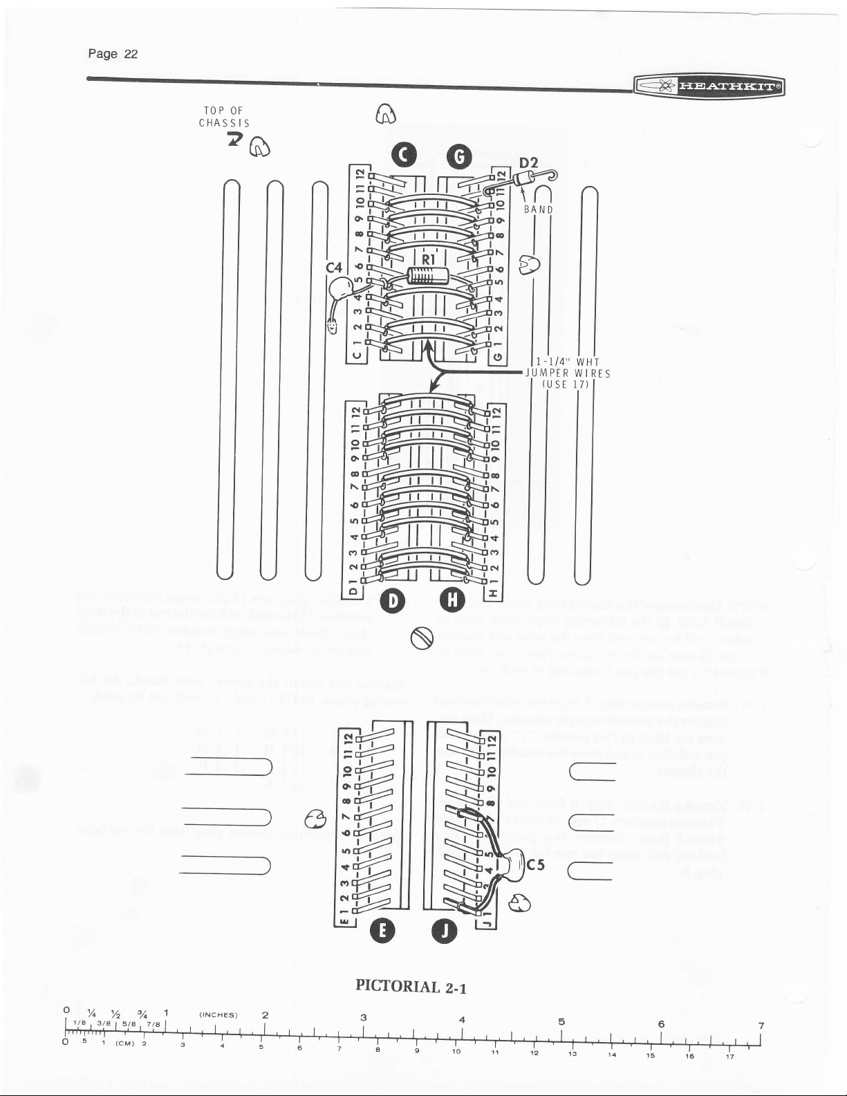
22
TOP OF
CHASSIS
z6
ff
lIl
llll
@
c
o@
ff
_lo
-----\
o
or
O
C
C
5C
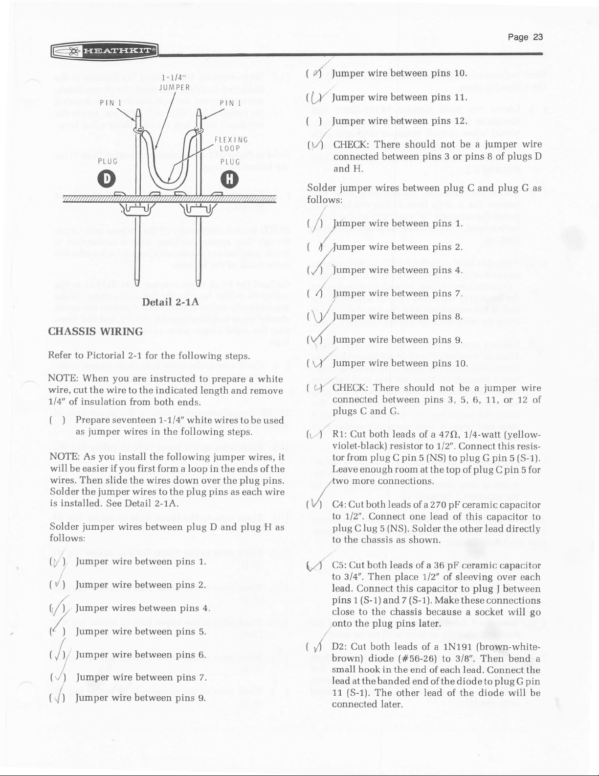
i-r/4"
JUMPFR
(
r'1
((-,Y
|umper
lrmper
wire between
between
wire
pins
pins
10.
11.
CHASSIS WIRING
Refer
to Pictorial
NOTE:
wire,
714"
(
NOTE:
will
wires.
Solder the
is installed.
Solder
follows:
When
cut the wire
insulation
of
Prepareseventeen
)
jumper
as
As
be easier if
Then
jumper
jumper
2-'1, for
you
to the indicated
from
wires in
you
install the following
you
the
slide
See Detail 2-1A.
wires between
Detail
are instructed
first form
wires to the
z-tA
the following
both
ends.
7-714'
whitewirestobeused
the following
a loop in the
wires down
plug pins
plug
steps.
prepare
to
length and remove
jumper
over
D and
steps.
wires, it
ends of the
plug
the
as
each
plug
a white
pins.
wire
H
as
(
)
|umper
/
CHECK:
$A
connected
and H.
Solder
follows:
(
/) l,umper
(
{
7Yu
(,/)
fumper
(
4
fumper
(!),/
/umper
(\/)
|umper
(UJa
Jumper
(
L+'/
CHECK: There
connected between
plugs
(s
R1:
)
violet-black)
tor
Leave
lwo
C4: Cutbothleads
tVl
to
plug
to
wire
jumper
p"r
C and G.
Cut both leads
from
enough room at
more
712".
lug
C
the chassis as shown.
between
There should
between
wires between
wire between
wire between
wire
between
wire between
wire between
wire between
wire
between
resistor
plug C pin 5 (NS)
connections.
Connect one lead
(NS).
5
pins
not be a
pins
3 or
plug
pins
pins
pins
pins
pins
pins
pins
should not be a
pins
47O,1/4-watt
of a
Io 712".
the top of
of aZ7OpF ceramiccapacitor
Solder the other lead
12.
jumper
pins
8
C and
1.
2.
4.
7.
8.
g.
10.
jumper
3, 5, 6, 1.1,
Connect this resis-
plug
to
of this capacitor to
pin
G
plug C pin
plugs
of
plug
wire
12
or
(yellow-
(S-1).
5
directly
wire
G as
5 for
D
of
w\
r/t
(r/
),,
r/t
I
(,/)i
('/)
(J
fumper
fumper
fumper
fumper
fumper
fumper
|umper
wire between
wire
between
wires between
wire between
wire between
wire between
wire between
pins
pins
pins
pins
pins
pins
pins
1.
2.
5.
6.
g.
7.
4.
C5: Cut both leads of a 36
\r4
to
lead.
pins
close to
onto the
.
(
D2:
r/)
brown)
small hook in
lead
11
connected
Then
314'.
Connect
(S-1)
1
and 7
the chassis because a
plug pins
Cut both leads of a 1N191
diode
at the banded
(S-1).
The
later.
place
112" of
this
capacitor to
(S-1).
later.
(#56-26)
the end
end of the
lead
other
pF
ceramic capacitor
sleeving over each
plug
Make
these connections
to 3/8". Then bend a
of each lead.
diode to
the
of
between
)
socket will
(brown-white-
Connect the
plug G pin
will be
diode
go
Refer
to
Pictorial
the
following
(
Locate
)
straighten
vidual
connector
nector
Pictorial
(
vJ Locate
remove
tween
be
damaged.
backine.
(
Yress
7f
tors
"
1. "
the large gray
end
lined
(rl
Remove
-
Then
have
bers 1 through
the numbers
with
move the paper
strip and
shown.
(
Cut numbers
4
maining
maining
the numbers
2-2
steps.
the
main harness
it
out as
wires
at
socket
socket
the
this
at A
has
2-2.
the remaining
the
A
numbers
Then
label
the
on
on the label
wire,
of the
connector)
up
with the
number
numbers
cut
a strip with
9 and 10.
numbers
10 through
press
13 through
number
strip
should have
1 through
(Illustration
shown. Position
each breakout
as shown.
its
slots up
chassis
strip from
"9"
remove
onto
harness.
is
lined
the
up with
(the
it.
and
double
Be
sure
letter
and the
hole
having
strip B from
17
and 18
the letter
16. Next,
B followed
cut this strip between
Save the
16 for later
backing
it
from
onto connector
18 from
strips
on the
12.
Booklet, Page
(#134-1OO1l
(BO)
BE SURE
or dovrn
plug
Cut the
"10"
so it
the protective
socket
that the
the hole
A
will be
number
the black
the label
off this strip
part
6) for
the indi-
and
each
each
con-
iust
label
label
will not
paper
connecnumber
having
on the
"10"
wire.
sheet.
so
by
num-
of this strip
use. Re-
the B
through
socket B
all
of the re-
sheet. Each re-
a letter followed
and
like
and
be-
is
you
as
by
{\t
Refer
the following
(
NOTE:
though
made, position
main
Connect
indicated
mechanically
shorter
nect
lugs.
(
NOTE:
9
solder lug BE
(V)
[.
Wrap masking
indicated
out numbers
Pictorial
on
breakouts
to Pictorial
Position
)
shown.
Do
not shorten
they
appear
trunk
of the harness.
the
black wires
solder lugs
wires
to solder
the
eight
Black
)
wire to the
chassis)
Do
not connect a wire in
Black
wire
(s-1).
Black
)
wire to the
(s-1).
tape around the harness
locations
and mark the
on the tape.
2-2. This will help
when
2-3
connect these wires later.
vou
(Illustration
steps.
the main
harness
any
of the harness
too long. After
any
excess
wire length
coming from
in the following
secure
connections.
lugs BE, BG,
longer
wires
lower hole
in
solder lug
at this time.
the lower
to
upper hole
proper
See the inset
you
drawing
locate
Booklet, Page 7)
on the
chassis as
wires
a
connection is
back under
BO#I4
steps.
Connect the
BI, and BM.
to the
BE
other four
(hole
(S-1).
solder
closest to
the upper hole
hole in solder lug BG
in
solder lug BG
the
at
break-
the
for
even
the
to
the
Make
seven
Con-
the
of
Remove
harness
tion
and install
connector
the labels
/l/'
(WE
(4..J
(q
K
Save the F label
[
\,z
,femaining
(
Mark the remaining
V
with
their
proper
the
point
ball
with
the kit.
the
correct label
sockets as follows.
exactly as
(v
/v
(il
0"')
labels,
shown in Pictorial
N
P
for
use
as
they will not be
harness
"S"
number
end
as shown. Use a felt
pen
and
and a numb
the
masking
on the
Be
sure to
later
and
discard the
used.
connector sockets
et 1..7 , or 8 at
tip marker
furnished
tape
proper
posi-
2-2.
or
(
(
(
{'
(')
()
-)
'..'
',')
1,
I
)
)
Black wire
(s-1).
Black
wire to the upper
(s-1).
Black
wire
ts-1).
Black
wire to the
(s-1).
Black
wire to
(s-1).
Black
wire to the
(s-1).
to the lower hole in
hole in solder lug BJ
to the lower hole in
upper
hole in
the lower hole in
upper
hole in
lug
BJ
BM
solder lug
solder
solder lug BM
solder lug
solder
lug
BF
BF
LI'
(
nlack wire to the
(S-t1'
lower hole in solder
lug BH
Connect the wires
harness to switch
coming
as follows:
SW2
from BO#r7 of
the
main
(
Black wire to the upper
\/)
hole in solder
(s-1).
i/)
(
Black wire to the lower hole in solder
ts-1).
( .)
Black wire to the upper hole
(s-1).
(
Black wire to
)
(s-1).
(
Black
I
wire to the upper hole in solder
(s-1).
(
CHECK: Solder lug BE
)
connected
(
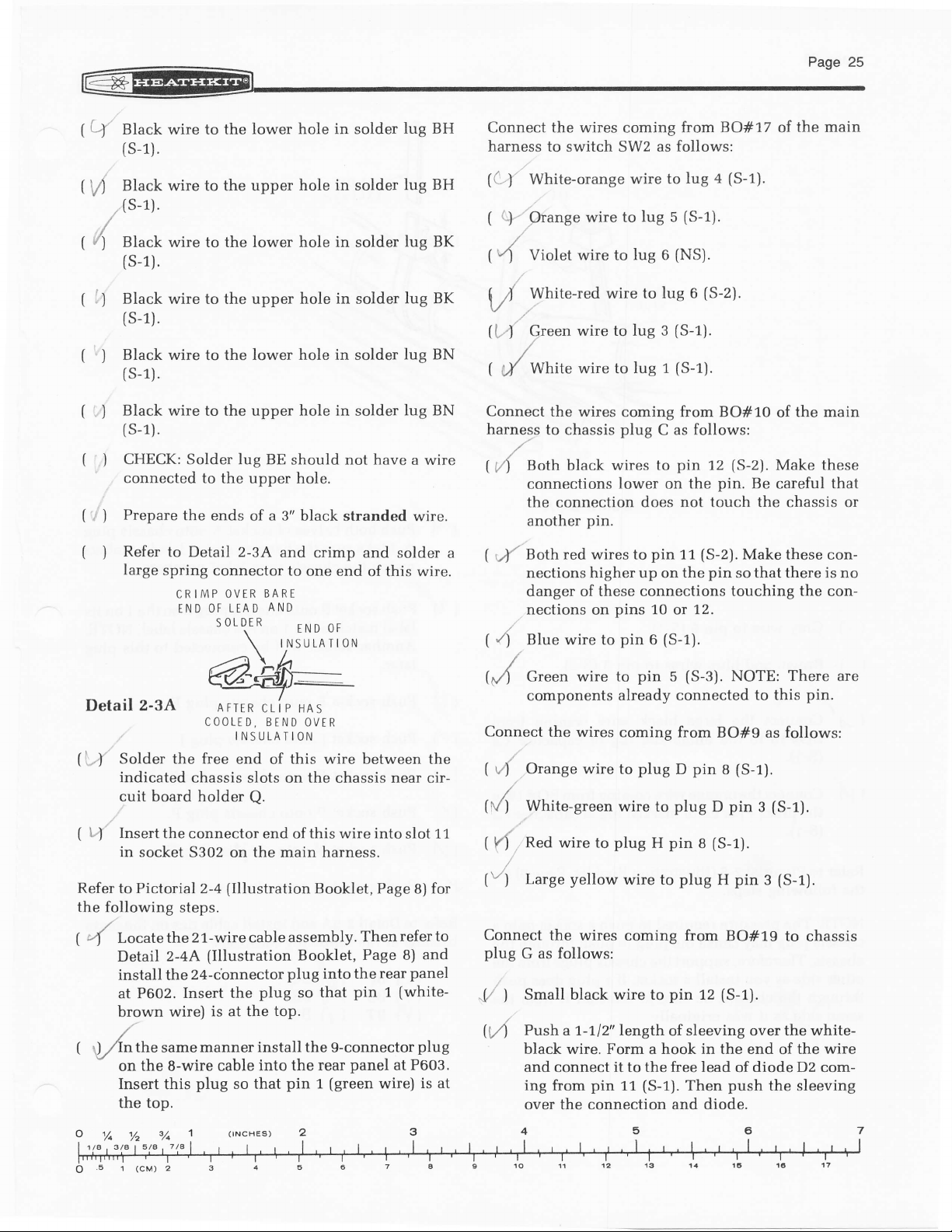
,, ) Prepare
(
Refer
)
large
the ends
to Detail 2-3A
spring
CRIMP
END
to the upper hole.
lower hole in solder
the
should not have a wire
of a 3" black stranded
and
crimp and solder
connector to
OVIR BARE
OF LEAD
SOLNR
\
one end
AND
END
INSULATION
in
OF
solder
BH
lug
lug BK
lug BK
lug BN
lug BN
wire.
of this wire.
a
((
White-orange
)'
i;.'
brange
1
(4
Violet
White-red wire to
\ /
Green
U..1
(
White wire to lug
;/
Connect
harness
(?4
Both black
wire to
wire to lug 6
wire to lug 3
the wires
to chassis
connections
the connection does
pin.
red wires to
1
,r(
another
Aoth
nections higher up on
danger
of
nections on
/)
(
Blue wire to
a
lug 5
lug
(S-1).
{S-1).
wire to
(NS).
(S-2).
lug 6
(S-1).
(S-1).
1
coming from BO#10
plug
wires to
lower on the
as follows:
C
pin
12
(S-2).
pin.
the main
of
Make these
Be
careful
that
not touch the chassis or
11
the
(S-2).
Make these con-
pin
that
so
there
is
no
pin
these connections touching the con-
pins
10
12.
or
(S-1).
pin
6
Detail 2-3A
Solder the free
{i...}'
indicated
cuit board holder
l'".'}
Insert
t
Refer to Pictorial
the
following
(
4
(
t)
,Anthe
the connector end of this wire into
in socket
steps.
Locate
Detail
install the
at P602.
brown
on the 8-wire cable
Insert
the top.
the
2-aA
Insert the
wire)
same
this
a-M_
AFTER
COOLED, BEND
chassis slots on the chassis near cir-
5302 on the main harness.
2-4
21-wire cable assembly.
(Illustration Booklet,
24-cbnnector
is at the
manner install the
plug
CLI P HAS
INSULATION
end of this wire between the
Q.
flllustration
so that
OVER
plug
plug
so
top.
into the
pin
slot 11
Booklet, Page
refer to
Then
Page 8)
rear
the
into
(white-
pin
panel
wire)
1
at P603.
that
9-connector
rear
(green
1
8)
panel
plug
for
and
is at
Green
0,4
components
Connect
(
,"ri'
(V)
(
!d
(")
Connect
plug
"l/'
U/1
the wires
Orange wire
White-green
Red wire
yellow
Large
the wires
follows:
G as
Small black wire to
)
Push a 7-1.12" \errgth
wire to
pin
5
already connected
coming from
plug D pin
to
plug D pin
pin
H
to
to
plug
wire to
wire
coming from BO#19
pin
of sleeving over
black wire. Form a hook in the end
and connect it to the free lead
L1
(S-1).
and diode.
ing from
pin
over the connection
(S-3).
NOTE: There
to this
BO#9 as follows:
(S-1).
S
(S-1).
s
plug
Then
12
pin
H
(S-1).
of
push
diode D2
pin.
(S-1).
3
(S-1).
3
to
chassis
the white-
the wire
of
com-
the sleeving
are
o
Pase26
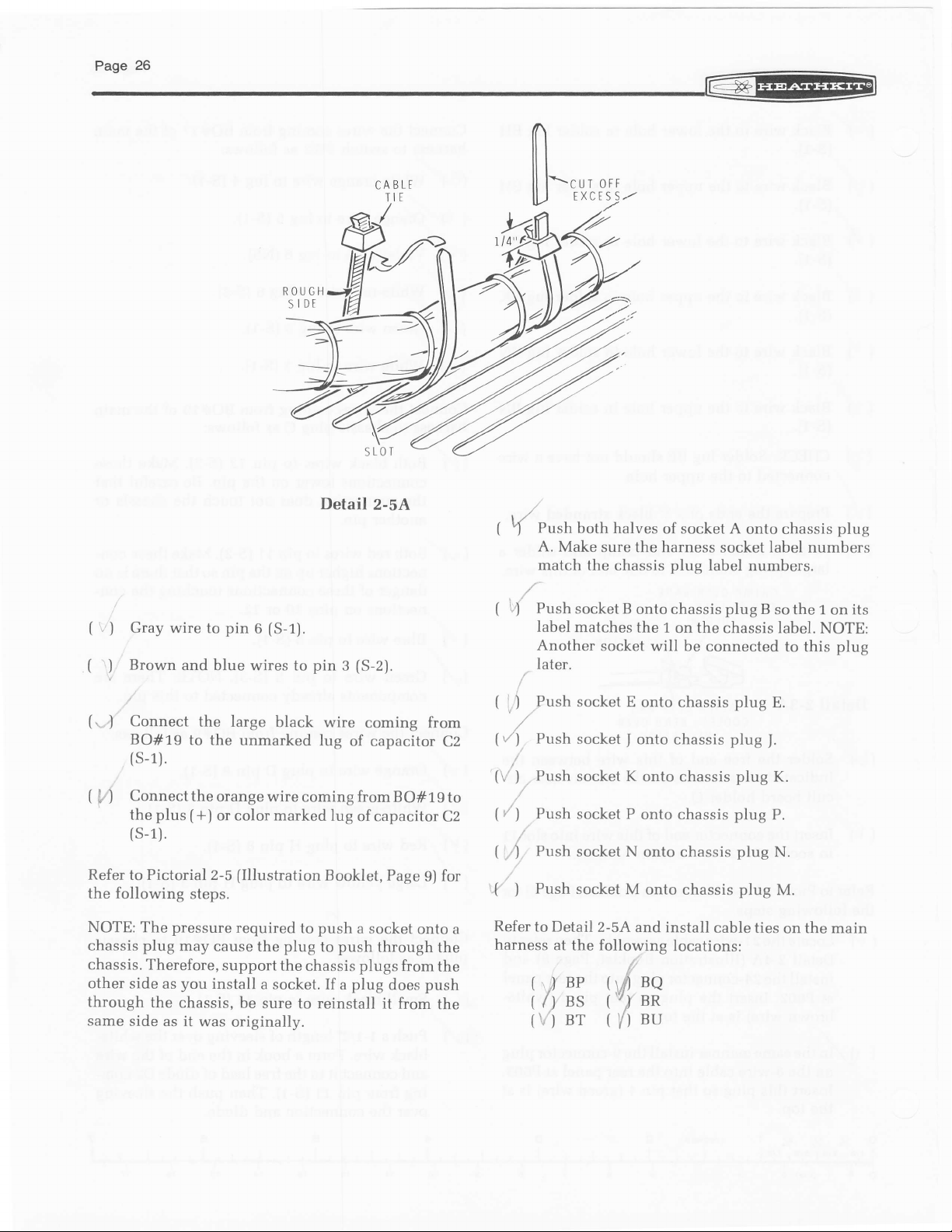
SLOT
t|]
OFF
CUT
EXCESS.,-
IIJ-
7
@
(
(
(,.
I
)
J
Gray wire
Brown
Connect
BO#19
pin 6 (S-1).
to
and blue wires to
the large
to the
(s-1).
(
Connect the
,' )
the
plus (+)
orange wire
or color marked
(s-1).
Refer to Pictorial 2-5
the following
NOTE:
chassis
chassis. Therefore,
other side
through
same
The
side as it
pressure
plug
as
the
steps.
may
cause the
support
you
install
chassis,
was
Detail
pin 3 (S-2).
black wire
unmarked lug
coming from
(Illustration
required
be
originally.
to
plug
the chassis
a socket.
sure to reinstall it from
of
lug
of capacitor
Booklet, Page
push
a socket
push
to
plugs
plug
If a
2-5A
coming from
capacitor
B
through
does
C2
O# 1 9 to
C2
for
9)
onto a
the
from
the
push
the
t,/
(
Push
1
A.
match the
( tl
Push
label
Another
later.
tl
Push socket
, ,/,
tvl
Push
f \ ' )
Push
(/')
Push socket P
.1
r
Push
Push
{')
Refer
to Detail
harness
'r)
/,)
\i')
both halves
Make
sure the harness
chassis
socket B
matches
socket
socket K
socket N
socket
at the following
ne
BS
BT
onto chassis
the 1
socket will be
E onto
onto chassis
I
onto chassis
onto chassis
onto chassis
M
onto chassis
2-5A
and install
nq
rl
'r7
BR
su
I{)
of socket A
socket
plug
label
plug
the
on
locations:
chassis label.
connected
chassis
plug
cable ties
onto chassis
label
numbers.
B
so the 1
to this
plug
E.
I.
plug
K.
plug
P.
plug
N.
plug
M.
on the main
plug
numbers
its
on
NOTE:
plug
L@
-
(Illustration
Refer to Detail
following six
the
(
t
t|/s.
(q
Locate the
t.
vi
straighten
nector socket as shown.
nector
,.Detail2-6A.
z. Locate the F strip that was set aside
t'
label sheet
paper
Press this
sure the number
with the hole having the two brown wires.
-
s. In
having'numbers 10
tor socket B.
2-6A
steps.
harness
bus
it
as
out
shown.
socket
backing.
the same manner, install the saved label
has its slots up or down
earlier,
label
and remove
onto socket connector
"1"
on
through 16 onto connec-
.-
Booklet, Page 10) for
(#734-1^o1z)
Position each
BE
SURE each
its
the label
is lined
and
concon-
just
like
from
the
protective
F. Be
up
NOTE:
tor, insert each clip
from
the slotted side of the socket.
the socket until it "clicks" into
each clip,
place.
Insert
BO#7
main
the spring clips
on the bus harness into
harness
Gray
6
Violet
,n
Blue
V
t(
17)r,'Green
/)
Yellow wire into hole 10.
you
When
pull
the wire to make
on
as follows:
wire into
wire into hole 7.
into
wire
wire into hole 9.
install
that the
so
hole 6.
hole 8.
a spring clip
on the wires
into
spring
place.
portion
Push
After
it
sure
coming
socket 5601
a
connec-
the
clip
you
is
locked in
Page2'
is
away
into
install
from
on the
(
.V
(
Refer
the following
(
(/
(,-4
Mark connector socket 5402
| V5.
you
If
,tr6.
to Pictorial 2-6
r)
Position
. shown.
PushsocketBfromthebusharnessontochassis
)
plug
the label
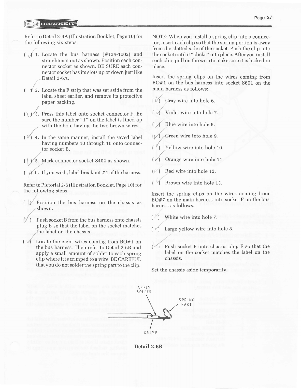
Locate
the bus harness. Then
apply a small
clip where it is
that
wish,label breakout
(Illustration
steps.
the bus
B
so that the
on the
the
you
do
eight wires coming from
not
harness
label
chassis.
amount
crimped to a wire. BE
solder the
on
refer
of solder to each spring
spring
as shown.
#r of the
Booklet,
on the chassis
the
to Detail 2-68
Page
socket
BO#1 on
CAREFUL
part
to the clip.
harness.
for
10)
as
matches
and
A P PLY
SOLDER
t {
[i )
(
Insert
BO#7 on the
harness as follows.
(/)
[
(/)
Set the chassis
or^ne wire into hole 11.
Red
Brown wire into hole
1
the
White
Large
")
Push
label
chassis.
into
wire
spring clips on
main harness
wire into hole
yellow
socket F onto
the
on
aside temporarily.
S PR
ING
PART
hole 12.
7.
wire into
chassis
socket
matches
13.
the wires coming
so
label
the
that the
into socket F on
hole 8.
plug F
the
on
from
bus
the
CRIMP
Detail z-08
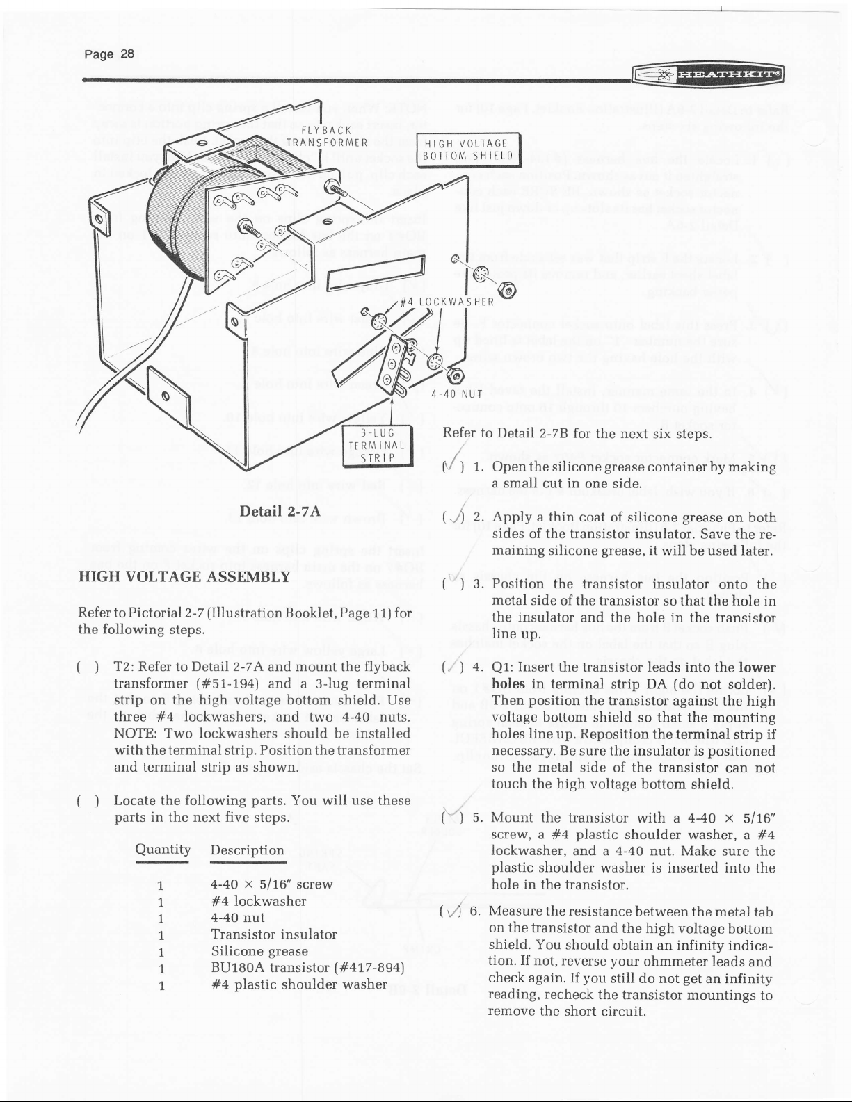
t"n"tt
TLYBACK
IRANSFORMER
VOLTAGE
HIGH
BOTTOM
,@
SHIELD
Detail 2-7A
HIGH VOTTAGE
Refer
to Pictorial 2-7
the following
(
T2:
)
Refer to Detail 2-7 A and mount the flyback
transformer
strip on the high
three
#4
NOTE: Two lockwashers should be installed
with
the terminal strip.
and terminal
(
Locate the following
)
parts
in the next five
Quantity
7
1
1
1
1
1
1
ASSEMBLY
(Illustration
steps.
(#51.-754)
voltage
lockwashers,
as shown.
strip
Description
4-40
#4lockwasher
4-40 nut
Transistor insulator
Silicone
BU180A
plastic
#4.
Booklet, Page
and a 3-lug terminal
bottom shield. Use
and two
Position
parts.
the transformer
You will use these
steps.
x
5/16" screw
grease
transistor
shoulder washer
3.LUG
INAL
TFRI\1
P
TR I
S
for
t t)
4-40
nuts.
(#417-894)
Refer
(V
1.
)
(J
2.
(
3. Position
)
4.
{,, )
to Detail
Openthesiliconegreasecontainerbymaking
a small
Apply
sides
maining
metal
the
line
Q1:
holes in
Then
voltage
holes line
2-7|_
cut in
a thin coat
the
of
silicone
the transistor insulator
side
insulator and
up.
Insert
the transistor
terminal strip DA
position
bottom shield so that
up. Reposition
necessary. Be
so the
touch the
S. Mount the transistor
i"t
screw,
metal side
high
a #4
lockwasher,
O. Measure
t,"4
plastic
hole
on the
shield.
tion. If
shoulder
in the
the resistance
transistor
You
not, reverse your
check again.
reading,
remove
recheck
the short
for the next
six steps.
one side.
of silicone
grease
transistor insulator.
grease,
of the transistor
it will
so that the hole in
the hole in
leads into the lower
(do
the transistor against
the terminal
sure the
voltage
insulator
the
of
bottom
transistor
with a 4-4O
plastic
shoulder
and a 4-40 nut. Make
washer is inserted into
transistor.
between
and the
should
high voltage
obtain an infinity
ohmmeter leads
you
If
still do not
get
the transistor
circuit.
on both
Save the re-
used
be
later.
onto the
the transistor
not solder).
the high
the mounting
strip
positioned
is
can not
shield.
x
5/16"
washer, a
#4
sure the
the
the metal tab
bottom
indica-
and
an infinity
mountings
to
if
 Loading...