

Heath Company Heathkit EC-1 Operational Manaual
EDUCATIONAL ELECTRONIC
ANALOG COMPUTER
MODEL EC-1
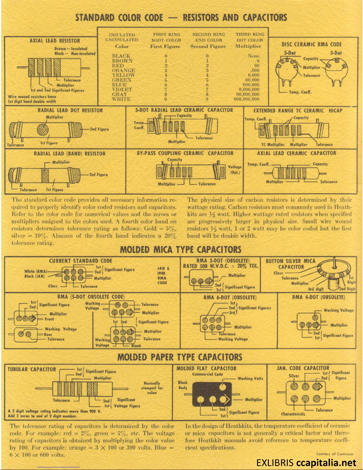
ST AN DARD COLOR CODE — RESISTORS A N D CAPAC ITORS
AX IAL LEAD RESISTOR
B row n — In sul ate d
B la ck — N on -in sula ted
T ol era nc e
M ul tip lie r
1st a nd 2n d Sig ni fic an t Fig ur es
W ire wo und re si sto r s ha ve
1st d igi t ba nd d oub le w idth
IN SU LA TE D
F IR ST RIN G
SE CO N D R ING
T H IR D R IN G
U N IN SU LAT ED
B O D Y CO LOR E N D C O LO R D O T CO LO R
C olo r First F i gure Secon d F i gure
M ulti p l ier
BL A C K 0
0 None
BR O W N
1
1 0
RE D 2 2 00
ORA N G E 3
3 ,000
YEL L OW
4 4
0,000
GRE E N 5 5
00,000
BL UE 6 6
000,000
VIO L ET
7
7
0,000,000
GRAY 8
8 00,000,000
W H ITE
9
9
000,000,000
DISC CERA M IC RMA CODE
5-Dot 3-Dot
C ap ac it y ,
M ul tip lie r
To le ra nce
Te mp . Co eff.
RADIAL LEAD DOT RESISTOR
M ul tip lie r
1st F igu re
2nd Fig ure
5-DOT RAD IA L LEAD CERAM IC CAPACITOR
• C ap ac ity
M ult ipl ier
To ler an ce
EXTENDED RANGE TC CERAM IC HICAP
Te mp . Co eff . r , / Ca pa cit y
f l I f U /,
TC Mu lt ipl ier M ult ip li er to le ra nc e
RADIAL LEAD (BAND) RESISTOR
M ul tip lie r
f
T ol er an ce 1s t Fi gur e
2nd Fig ur e
BY-PASS COUPLING CERAMIC CAPACITOR
Ca pa cit y
rH i i W il v; a,T
AX IAL LEAD CERAMIC CAPAC ITOR
Te mp . Co ef f. — , ,
----------------
Ca pa cit y
M ul tip lie r
T ol era nc e
/ M l
M ul tip lie r
T ol era nc e
The standard color code provides all necessary information re
quired to properly identify color coded resistors and capacitors.
Refer to the color code for numerical values and the zeroes or
multipliers assigned to the colors used. A fourth color band on
resistors determines tolerance rating as follows: Gold = 5%,
silver = 10%. Absence of the fourth band indicates a 20%
tolerance rating.
M OLD ED M ICA TY PE CAPACITORS
The physical size of carbon resistors is determined by their
wattage rating. Carbon resistors most commonly used in Heath-
kits are Y i watt. Higher wattage rated resistors when specified
are progressively larger in physical size. Small wire wound
resistors x / i watt, 1 or 2 watt may be color coded but the first
band will be double width.
CU RRE N T STANDAR D CODE
W hi le (R MA ) 2 nd
f Sisn ifitan f
f i9 ure
Bl ack (JA N)
C la ss
M ult ip lie r
T ole ran ce
JA N &
194 8
RM A
CO DE
RMA 3-DOT (OBSOLETE)
RATED 500 W .V .D .C. ± 20% TOL.
M ul tip lie r
| Si gn ifi ca nt F ig ure
BUTTON S ILVER M ICA
CAPAC ITOR
C la ss
-
To le ra nc e
M ul tip lie r
3r d di git
W o rk ing -
V olt ag e
M ul tip lie r
3 F ron t
- W ork ing V olt ag e
* R ea r
— To ler an ce
RMA (5-DOT OBSOLETE CODE)
j S ign ific an t Fi gur e
- To le ra nce
1st 2 nd
W ork ing
V olt ag e
— M u lt ipl ier
Si gn ifi can t Fig ure
>
-----
M u lti pli er
^ To le ran ce
Bl ank
RMA 6-DOT (OBSOLETE)
1st,
- 2 nd ^ Sig nifi can t Fig u re s
- 3 rd )
- M u lti pli er
T ole ra nc e
W ork ing Vo lta ge
RMA 4-DOT (OBSOLETE)
W ork ing Vo lta ge
M u ltip lie r
Si gni fica nt F igu re
M OLD ED P APER TYP E CAPACITOR S
TUBULAR CAPACITO R
Si gni fica nt F igu re
M ul tip lie r
i -
MOLDED FLAT CAPACITOR
C om m erc ial Cod e
JAN. CODE CAPACITO R
— 1 st / S ign ific ant
To le ra nc e
N orm al ly
st am pe d f or
va lu e
A 2 d igi t v ol tag e ra tin g i n d ic ate s m o re tha n 9 00 V .
Ad d 2 ze ro s to end of 2 d ig it n um ber .
Si gni fica nt
V o lt ag e F igu re
W ork in g V ol ts
M ul tip lie r
S ilv er
Si gni fica nt Fig ur e
Fi gur e
M ul tip lie r
Ch ar ac te ri sti c
To le ran ce
The tolerance rating of capacitors is determined by the color
code. For example: red = 2%, green = 5%, etc. The voltage
rating of capacitors is obtained by multiplying the color value
by 100. For example: orange = 3 X 100 or 300 volts. Blue =
6 X 100 or 600 volts.
In the design of Heathkits, the temperature coefficient of ceramic
or mica capacitors is not generally a critical factor and there
fore Heathkit manuals avoid reference to temperature coeffi
cient specifications.
Courtesy of Centrolce
EXLIBRIS ccapitalia.net
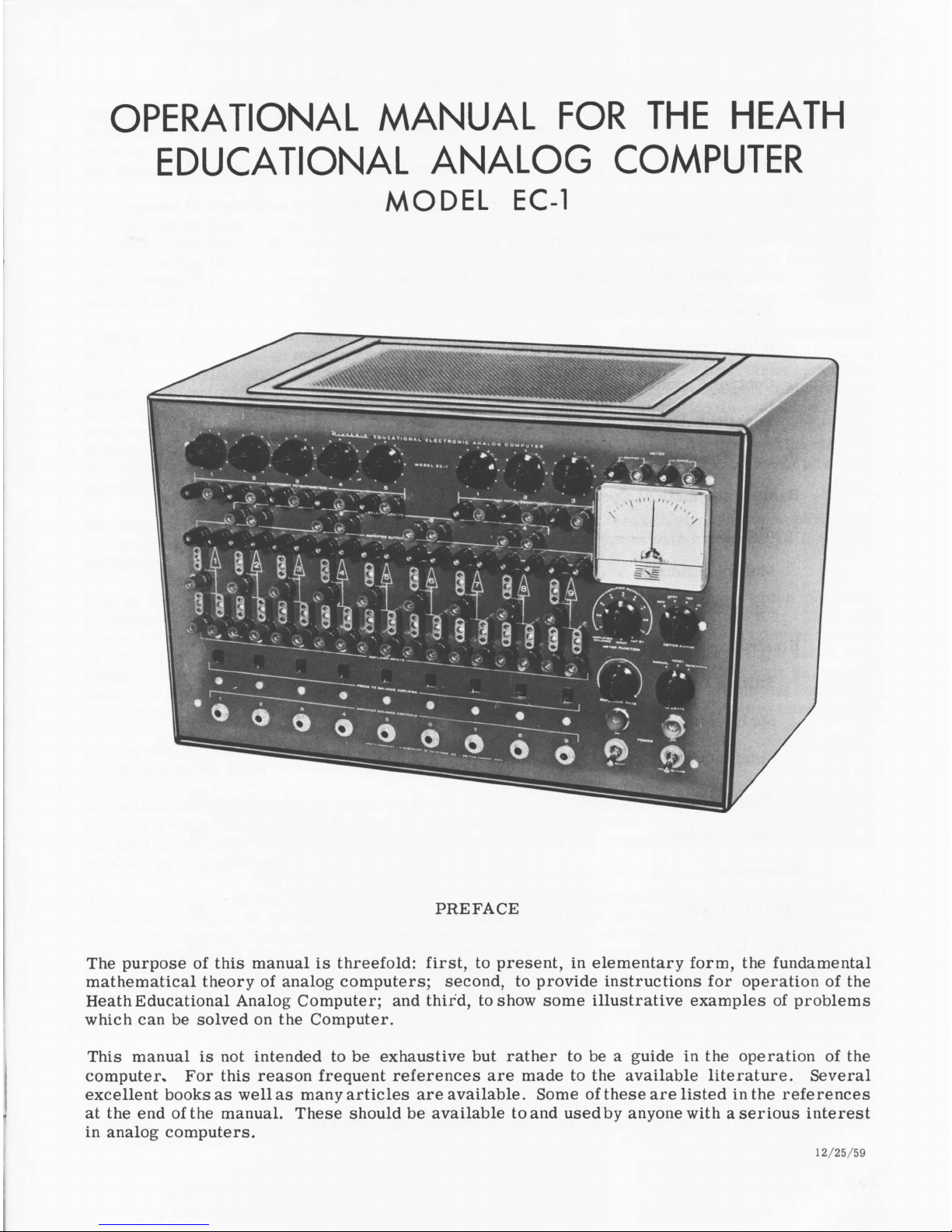
OPERATIONAL MANUAL FOR THE HEATH
EDUCATIONAL ANALOG COMPUTER
MODEL EC-1
PREFACE
The purpose of this manual is three fold: f irst, to present, in ele m entary form , the fundamental
mathem atical th eory of analog com p u ters; second, to provid e instru ctions f o r operation o f the
Heath Educational Analog Com puter; and third, to show some illustrative examples of proble m s
which can be solved on the Com puter.
This manual is not intended to be exhaustive but rather to be a guide in the operation of the
com puter. For this reason frequent re fe r e nc e s are made to the available lite rature. Several
ex cellent books as well as many articles are a v ailable. Some o f these are listed in the r e fe r e nce s
at the end of the manual. Th ese should be available to and usedby anyone with a seriou s interest
in analog com puters.
12/25/59
Prefa ce
CONTENTS
1
Introdufction
.......................................................................................................
3
Theory
..................................................................................................................
4
Circuit D e scriptio n
DC Operational A m p lifier
.......................................................................
13
Am plifier Power Supply
...........................................................................
14
Initial Condition Power S u p p li e s
.............................................................
15
Control C i r cu it
.............................................................................................
15
Repetitive O s c i l la to r
..................................................................................
15
General Operating I n st r u ct i o n s
....................................................................
16
Basic M athematical Operations
A d d itio n
............................................................................................................
17
M u ltiplica ti o n
................................................................................................
19
Integration
.......................................................................................................
19
Illustrative Problem s
Falling Body
................................................................................................
21
Spring-M ass S y s t e m
...........................•....................................................
24
Simultaneous A lg e braic E qu a tio n s
.........................................................
26
P ro j e c t i le
.......................................................................................................
27
Bouncing B a l l
.......................................
28
R e fe r e n c e s
...........................................................................................................
31
S p e c i f ic a t io n s
....................................................................................................
32
Parts L i s t
...........................................................................................................
36
S c h e m a t ic
..........................................
. 40
Page 2
INTRODUCTION
One of the wonders of the modern E le ctr o n ic A ge is the com puter or "Giant Brain ", as it is
som etim es called. Actually, the computer is not a "B rain” at all, sin ce it d o e s not think but
must be " t o ld " what to do. It is capable of doing mathematical operations at much greater speed
and with greate r accu r a cy than human bein gs.
A computer is a machine which p e r form s physical o p eration s that can be d escrib ed by m athe
matical operations. In general, com p u ters may be classified as d igital or analog. Digital
com pu ters opera te by d is c r e te steps, that is , they actually count. Com m on examples of digital
com pu ters a re the abacus, desk c a lcula tor, punched-card machine, and the modern electron ic
digital com puter. The fundamental o p erations p e r form ed by the digital com puter are usually
addition and subtraction. Multiplication , fo r example, is a ccom plished by repeated additions.
Analog com p u ters operate continuously, that is, they m easu re. Examples of analog com puters
ar e the s lide rule (which m easures lengths), the mecha nical diffe rentia l analyzer, the ele c tro
mechanical analog computer and the al l-e le ctr o n i c analog com puter. The last three gen erally
measu re ele c t r ic al volta g es o r shaft rotations. P h ysica l quantities such as weight, temperature
or area a r e represe n ted by voltages. Voltage is the elec t r i c a l analog o f the v a riable being
analyzed. A rbitrary s ca le fa c to r s are set up to relate the voltages in the computer to the va r
iables in the problem being solved . For example, 1 volt equals 5 feet or 10 v o lts equals 1 pound.
The name "an a log" co m e s from the fact that the computer solves by analogy by using physical
quantities to represent numbers.
The fact that the analog computer op erates continuously m akes it v e ry useful in such operations
as integration; for this rea son com puters used this way are so m etim es known as Differential
Analyzer s.
One of the m ost powerful applications o f analog com p u ters is simulation in which physical
pro p e rtie s, not easily v a ried , are re p r esented by voltages which are ea s ily varie d . Thus the
"knee actio n " o f an autom obile front wheel suspension can be simulated on an analog com puter
in which the weight of the automobile, the constant of the spring, the damping of the sh ock ab
so r b e r , the nature o f the road surfa c e , the tire p r e s s u re and other conditions can be re p re
sented by voltages. In pra c tice these f a c to rs cannot be r ead ily changed, but on the com puter
any one o r all of these may be varied at w ill and the resu lts observed as the changes a r e made.
Analog com p u ters are es p ecia lly useful in solving dynamic problems in which the motion can be
expressed in the form of a differe n tia l equation.
All mathematical operation s n ecessary to the solution of ordinary differential equations can be
built up from addition, multip lication by a constant, and integration. * As w ill be shown later,
the analog com puter can per form these opera tio n s and thus is a convenient de v ice for the solution
of d ifferential equations.
The combination o f the six b a sic com puter opera tio n s w ill perfo r m any continuous function.
Some of the types o f p roblem s which can be solve d by these m ethods are radio a ctiv e decay,
ch e m ic a l reaction, beam oscillation and heat flow. With the addition of crystal diod es and re
lays, simulation of discontinuous fun ctions is p ossib le . Th is makes p o s s ib le solution o f pro b
lem s involvin g saturation, backlash, hy st e r e s is, friction , lim it stops, vacuum tube ch arac te r
is tic s, and different m od es o f operation such as sonic vs. subsonic flow.
* Shannon, C . , JOURNAL MATH. AND PHYSICS, Vol. 20, Pages 337-354, 1941.
Page 3
With the addition of special devices such as function gen erator and function m ultiplier, add i
tional opera tions may be perform ed such as m ultiplication o f v a riab les, computation o f tr ig
on om e tric , exponentional and logarithm ic functions and generation of discontinuous functions. *
THEORY
In o r d er to s olve d ifferen tial equations on an analog computer, it is ne c e s s a ry to have:
1. DC am plifie r s (also called op erational am plifiers) capable of p erform in g the operation
of
a. Integration
b. Addition (or summation)
c. M ultip lication by a constant
d. M ultiplication by -l(i n v e rsio n )
2. A m eans o f setting coefficien ts in a problem . This may be done by means of
a. Potentiom eters
b. Changing the ratio of feedback re s istan c e to input resista nce.
3. A control system for starting and stopping solution of the proble m , as w ell as resetting
the initial conditions so a s to be ready for running a new solution with the same or new
coefficien t s and initial conditions.
The general p ro c ed u r e in solvin g a p ro b lem is to:
1. Set the machine v a riab les (voltages) to the co rr e ct initial conditions.
2. Make the computing elem ents op e rative and f o rc e the volta g es to vary in the manner
pr e scribe d by the d ifferen tial equations.
3. O b serve a nd /or re cor d the voltage variations, with r e spect to tim e, which constitute
the solution o f the given prob lem .
4. Stop the machine and re s e t fo r a new run.
The heart o f the analog compu ter is the DC operational am p lifier which pe r fo r m s the basic
mathematical oper a tio n s ne c e s s a ry for the solution o f proble m s .
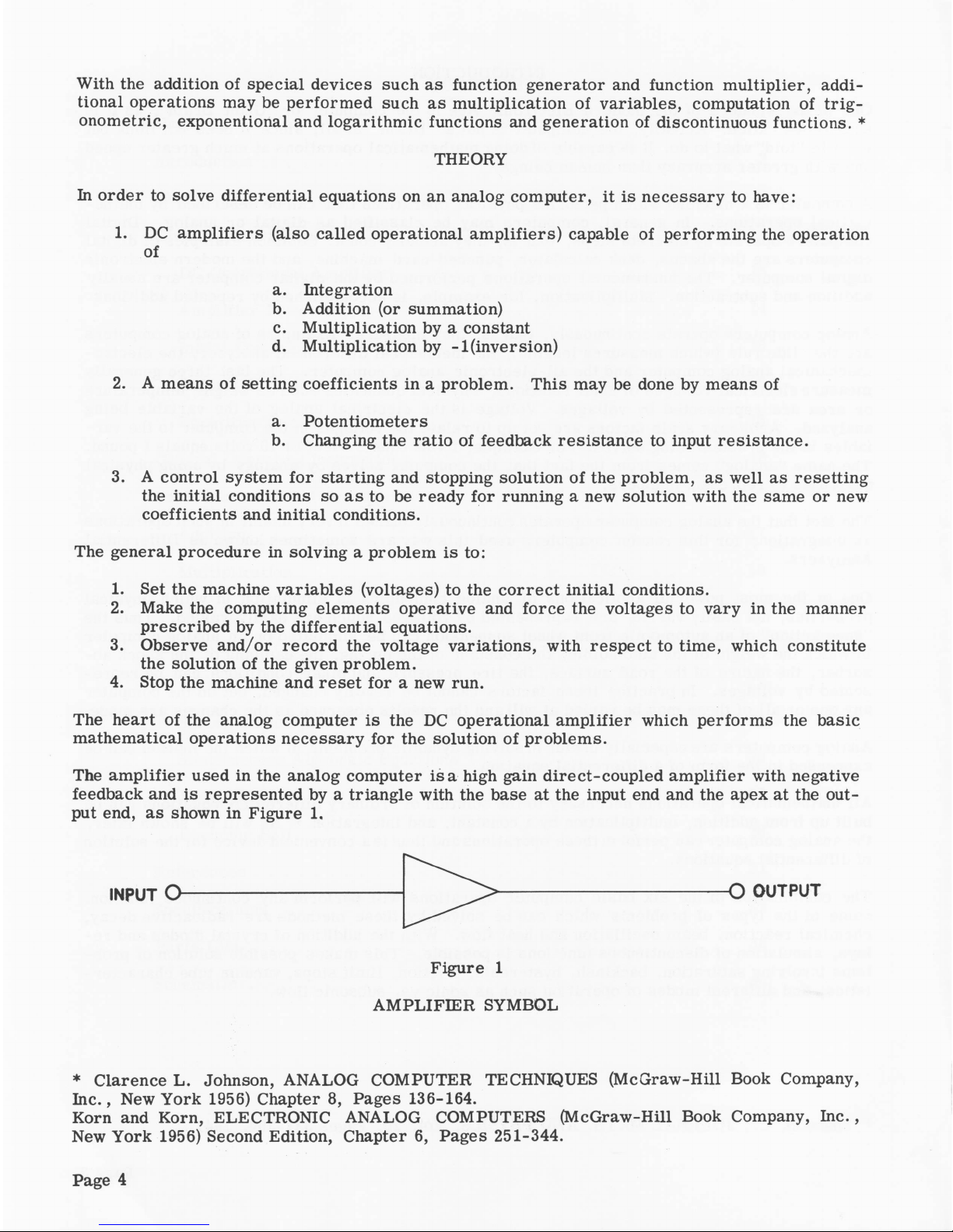
The am plifier used in the analog com pu ter is a high gain d ir ect-c o up le d a m plifie r with negative
feedback and is repre sented by a triangle with the base at the input end and the apex at the out
put end, as shown in Figure 1.
INPUT O -
-O OUTPUT
Figure 1
AM PLIFIER SYMBOL
* Claren ce L. Johnson, ANALOG COMPUTER TECHNIQUES (McGraw -H ill Book Company,
In c ., New York 1956) Chapter 8, Pages 136-164.
Korn and K orn, ELECTRONIC ANALOG COMPUTERS (McGraw-H ill Book Company, In c . ,
New York 1956) Second Edition, Chapter 6, Pages 2 51-344.
Page 4
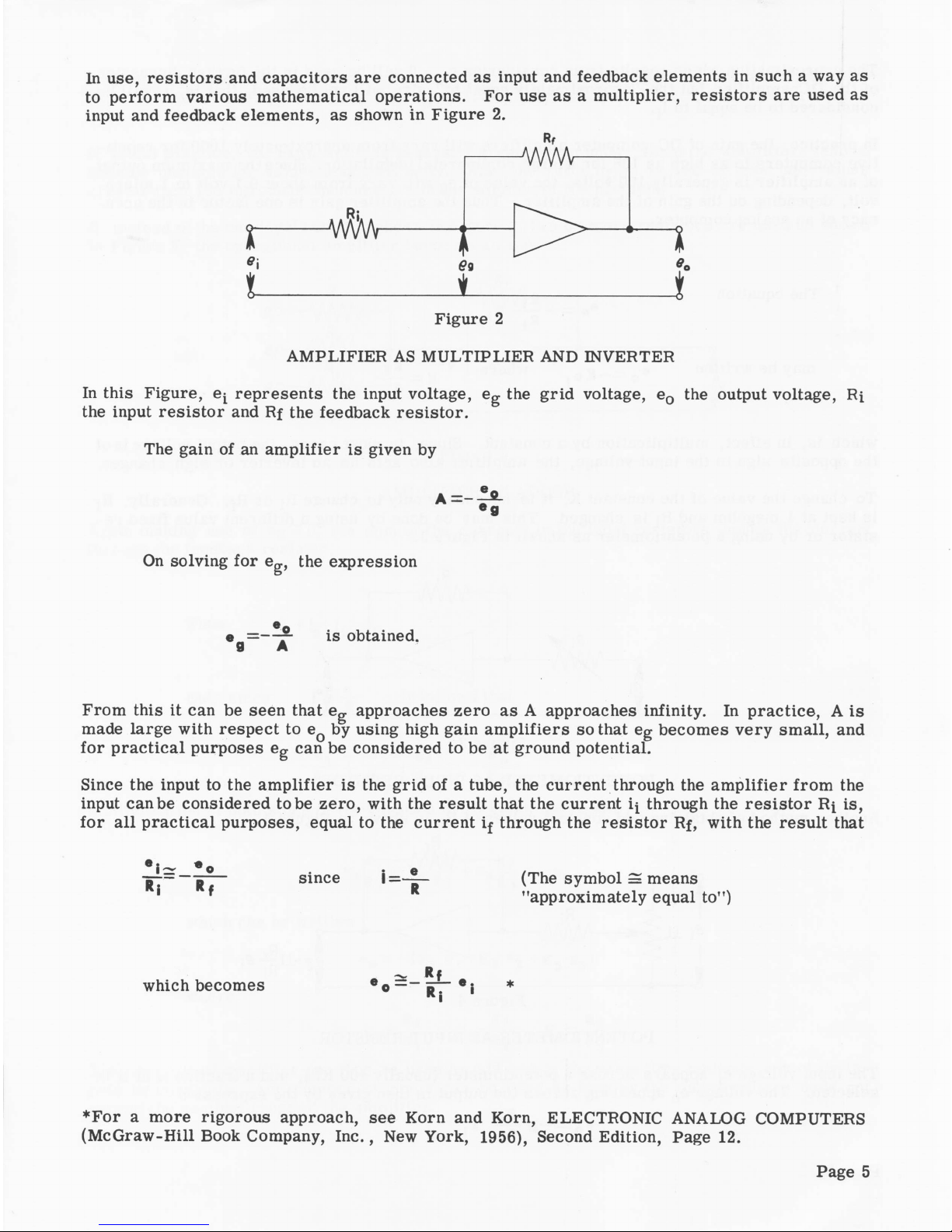
In use, res is t ors and capacito r s are conn ected as input and feedb ack elem ents in such a way as
to p e r form va rious mathem atical operation s. F o r use as a m ultiplier, re sist o rs are used as
input and feedba ck elem en ts, as shown in Figure 2.
Rf
AM PLIFIER AS MULTIPLIER AND INVERTER
In this Figure, e i represents the input voltage, e g the g r id voltage, e0 the output voltage , Ri
the input re s i s tor and Rf the feedback r e sisto r .
The gain of an amp lifie r is given by
On solvin g fo r eg, the expression
e = — . is obtained.
9 A
From this it can be seen that e g app roaches ze r o as A approaches infinity. In pr a ctice, A is
made large with respe ct to eQ by using high gain a m p lifiers s o that eg becom es ve r y small, and
for p ra ctica l purposes eg can be considered to be at ground potential.
Since the input to the am p lifie r is the grid of a tube, the curren t through the am plifie r from the
input can be consid e r ed to be z e ro, with the res u lt that the current if through the re sist o r Rf is,
for a ll p r a ctica l pu r poses, equal to the current if through the re s is tor Rf, with the resu lt that
* l ~ * o . e
-jp -- — jj— since I — (The symbol = means
' * "approxim ately equal to")
2s Rf
which becom es eo — — # s
* i
♦For a more rig o r o u s approach, see Korn and Korn, ELECTRONIC ANALOG COMPUTERS
(M cG ra w-H ill B ook Company, In c., New York, 1956), Second Edition, Page 12.
Page 5
The approxim ation which resu lts from consid e ring e = 0 w ill be used in the further discu ss ion
of the DC a m plifier but the "approximately equal to*' sign w ill not be used, that is , i^ will be
consid e red to be eqqal to if.
In p r a ct ice, the gain of DC computer am plifie r s will v a r y fr om approxim ately 1000 fo r re p eti
tive com p u ters to as high as 10° for a la rge c o m merc ia l installation. Since the maximum output
of an am p lifier is genera lly 100 volts, the value of eg w ill vary from about 0.1 v o lt to 1 m ic r o
volt, depending on the gain o f the a m plifier. Thus the am plifier gain is one fa c tor in the accu
racy of an analog com puter.
The equation
e
o
5 l _ e .
may be w ritten e_ — „ where
o - K . . K - —
which is , in effe c t, m ultiplica tion by a constant. Since, in most cas e s, the output voltage is of
the opposite sign to the input voltage, the am plifie r als o acts as an inverter or sign changer.
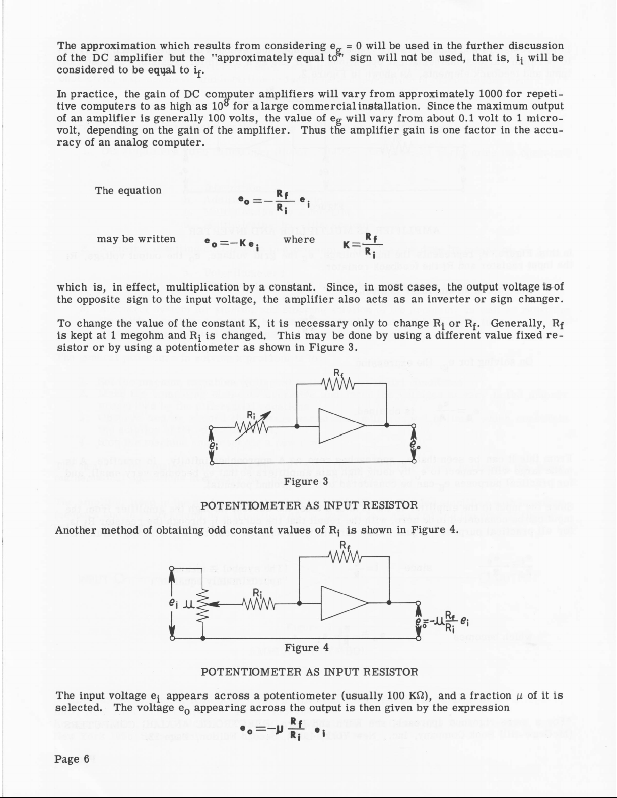
To change the value of the constant K, it is n ecessa ry only to change Rf o r Rf. Generally, Rf
is kept at 1 megohm and Rj is changed. This may be done by using a different value fixed r e
sistor o r by using a potentiometer as shown in F igure 3.
POTENTIOMETER AS INPUT RESISTOR
Another method of obtaining odd constant values of Rj is shown in Figu re 4.
POTENTIOMETER AS INPUT RESISTOR
The input voltage ef appears ac r oss a poten tiometer (usually 100 Kfl), and a fraction p of it is
se lected. The voltage e0 appearing a c ro s s the output is then given by the expression
Page 6
Suppose, f o r example, a ratio of 3.7 is des ired. If ji is made equal to 0.37 and R f/R f = 10
(R f = 1 megohm and Rf = 100 Kfi), then eQ = -3.7 ej. Generally this method is to be preferre d
ov e r that shown in Figure 3.
In actual p r a ctice, the ratio R f/R f is g enerally greater than unity, sin ce the am p lifiers tend to
be com e unstable for values le s s than unity. Also the ratio Rf/R f is 100 or le s s, as values
greater than 100 introduce inaccuracies in the solution of the proble m .
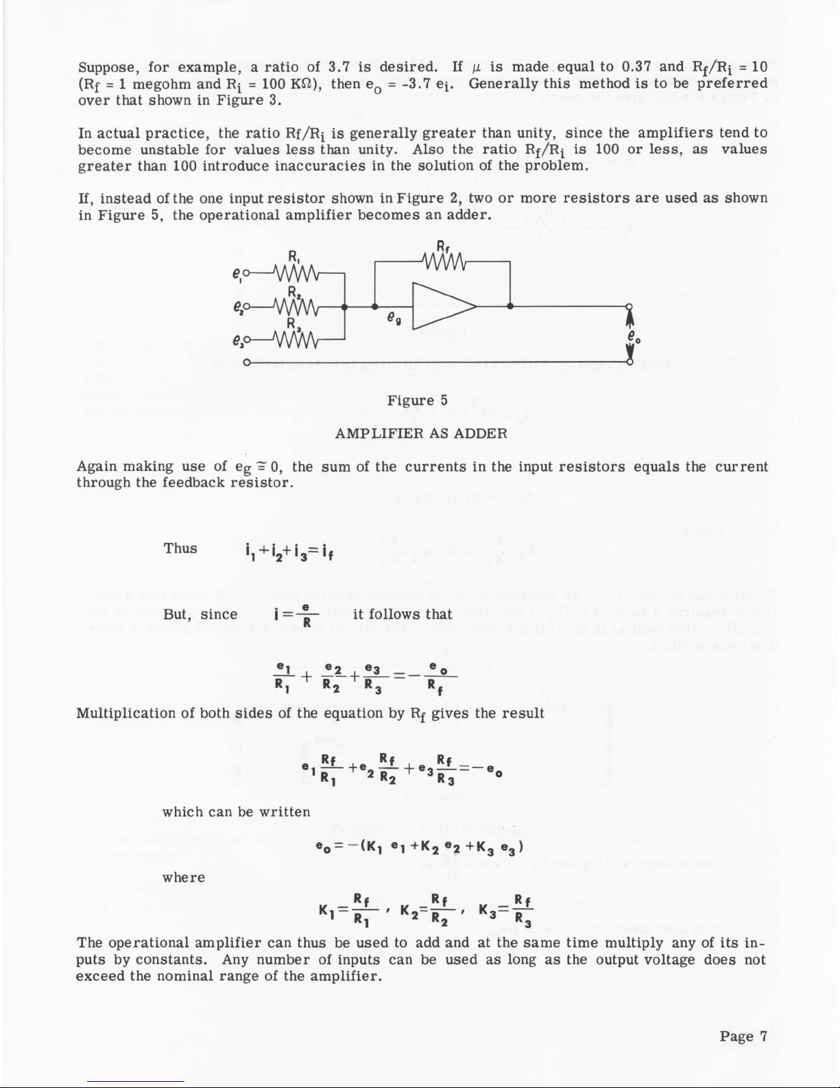
If, instead of the one input r e s is t o r shown in Figure 2, two or more re sisto r s a re used as shown
in Figure 5, the operational am p lifier b e co m es an adder.
e°— VW W —
e ,o -J W M r -
e , * - J
WvW-
- M / W -
e0
i
Figure 5
AMPLIFIER AS ADDER
Again making use o f eg = 0, the sum of the curre n ts in the input res is t o rs equals the curren t
through the feedback r e sis tor.
ThUS i, + '2+ i 3= 'f
But, sin ce i = _ | r it follo w s that
—L . e 2 . e 3 —
D + R* + R3
L1 " 2 " 3 - 'f
Multiplication of both sides of the equation by Rf giv es the result
S t + . .* L = -
1
R, 2 R2 + ° 3 R 3
which can be written
e 0 — ( K , e , + K 2 e 2 + k e , )
Rf
K2=R-
where
= Rj_
[1 2 R2
The operation al a m plifier can thus be used to add and at the same time multiply any of its in
puts by constants. Any number of inputs can be used as long as the output voltage does not
exceed the nominal range of the am p lifie r.
Rf
K 3= R
3
Page 7
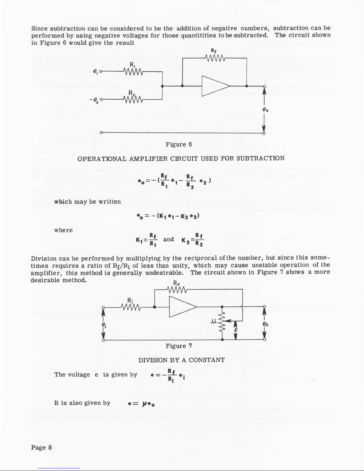
Since subtraction can be consid e red to be the addition o f negative num bers, subtraction can be
perfo rm ed by using negative voltages for those quantitities to be subtracted. The cir c u it shown
in F igure 6 would give the result
o
--------------------------------------------------------------------------------
1
Figure 6
OPERATIONAL AMPLIFIER CIRCUIT USED FOR SUBTRACTION
which may be written
where
- i t
and
Rf
K2 = r7
Division can be p erform ed by multiplying by the r e cipr o ca l of the number, but sin c e this som e
times requires a ratio o f R f /R i o f le s s than unity, which may cause unstable operation of the
am p lifier, this method is genera lly undesirable. The circu it shown in Figure 7 shows a m o re
desirab le method.
DIVISION BY A CONSTANT
The voltage e is given by
It is also given by e = p e 0
Page 8
where \i is the ratio of the voltage e0 appearing a c r os s the poten tiom eter to the voltage
acr o ss the arm of the potentiom eter and ground.
R f
Thus p e_ = — - — e i
° R:
and e_ = — ®
Thus divis ion by \i has been a c com plished if R f/R f is made unity (Rf = Rf = 1 megohm, fo r
example).
Since p is les s than unity, a s cale factor must be introduced when dividing by num bers la r g e r
than one. Let the desir e d d iv isor be 2.5. The value chosen for p. would then be 0.25, since p is
le s s than one. The indicated result (answer) w ill then be greater by a factor of 10 than the true
value of the answ er, so the indicated answer must be divided by the same value as used in r e
ducing the d ivision to a value of less than one (in this case 10). Thus, for this example
®o 0.25 1 10 1 Rj "i
since 2.5 = 0.25 x 10
ch oosing Rj = r.= imeg, this b e com es
1 / 1 x
eO - 0.25 *10' e i
which b e c o m es 10 « 0 —~ q 25 *■
If the divis o r had been 25, a facto r o f 100 would have been chosen, yielding
100 ®o o.25 *■
and the indicated resu lt would be divided by 100. If the division is le ss than unity, no co r r e cti o n
is ne cessary.
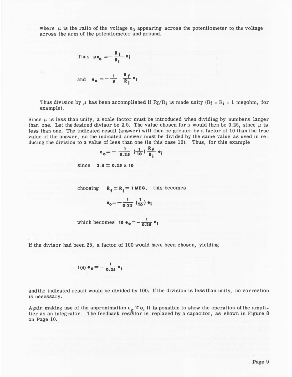
Again making use of the approximation e „ = o, it is po ssible to show the operation of the am pli
fie r as an integrator. The feedback re s is tor is repla ced by a ca p acitor, as shown in Figure 8
on Page 10.
Page 9
OPERATION AL AMPLIFIER AS INTEGRATOR
e i _ ■_ dQ
Rj d t
Since dQ = efdeQ this b e c o m es
Solving this equation for deQ giv e s the resu lt
de0 =— ei<**
Rj cf
Integration of both s ides g ives
Where eiC is the constant of integration
(initial condition) and is the voltage
ac r o ss the capacitor Cf at time t = o.
Thus the operational am plifier can integrate.
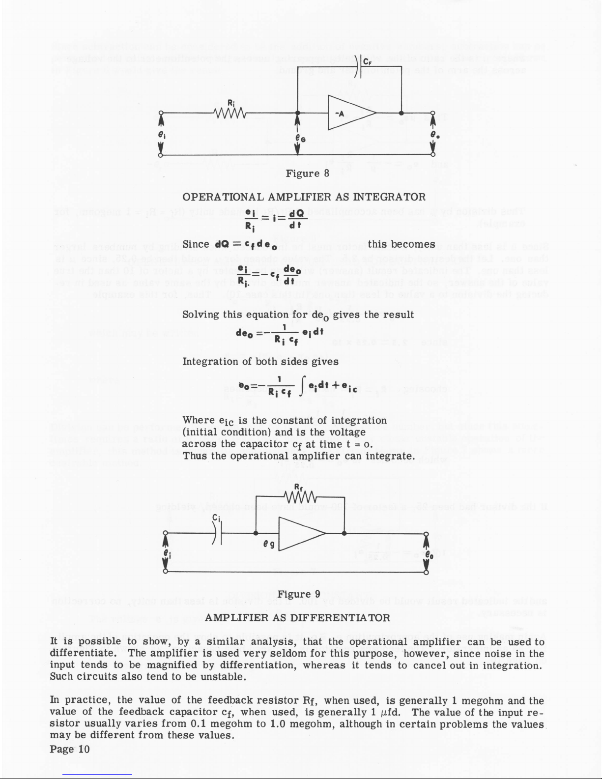
Figure 9
AMPLIFIER AS DIFFERENTIATOR
It is possib le to show, by a sim ila r analysis, that the operational am plifier can be used to
differentiate. The a mp lifie r is used v e r y seldom f o r this purpose, however, since nois e in the
input tends to be magnified by differentiation, whereas it tends to ca n ce l out in integration.
Such cir c u its also tend to be unstable.
In p ractic e , the value of the feedback re s is tor Rf, when used, is genera lly 1 megohm and the
value o f the feedback capacito r Cf, when used, is g en e rally 1 pfd. The value of the input r e
sistor usually va r ie s from 0.1 megohm to 1.0 megohm , although in cer tain problem s the values
may be different fro m these values.
Page 10
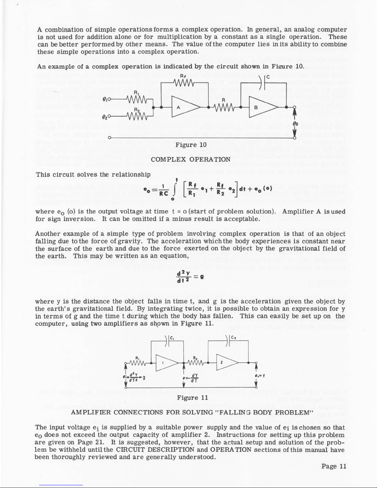
A combination of sim ple operations fo r m s a com p lex operation. In gene ral, an analog com puter
is not used for addition alone or for multiplication by a constant as a single operation. These
can be better perform ed by other means. The value o f the computer lie s in its ability to combine
these simple opera tions into a com plex operation.
An example of a c om plex operation is indicated by the cir cu it shown in Figure 10.
c
ei<>-
e'°— W W Vn
-A/WVW
-AAM/V
-A/WW
1
eo
J
Figure 10
COMPLE X OPERATION
Th is circu it s o lve s the relation ship
— l - r r ^ -
RC J L Rl
e* ] dt
+ en (o)
where e0 (o) is the output voltage at time t = o (start of prob lem solution). A m p lifier A is used
fo r sign inversion. It can be omitted if a minus resu lt is acceptable .
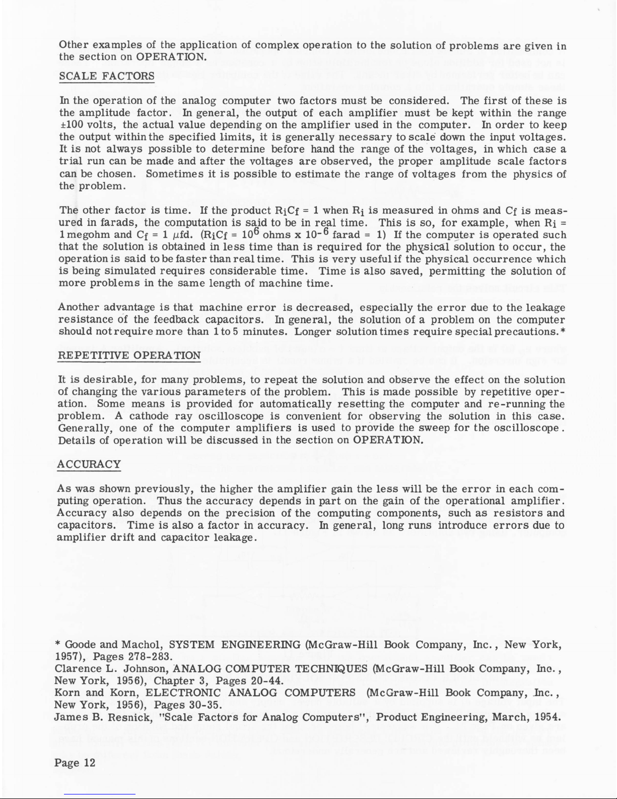
Another example of a sim p le type of pr oblem involving com plex opera tion is that of an o b ject
falling due to the force of gravity. The acceler a t ion which the body e x p erien c e s is constant near
the surface of the earth and due to the fo rce exerted on the object by the gravitational field of
the earth. This may be written as an equation,
d * y _
dt 2 -
where y is the distance the object fa lls in tim e t, and g is the accele r a t ion given the object by
the earth's gravitational field. By integrating twice, it is p oss ible to obtain an ex p r e s s ion for y
in term s of g and the time t during which the body has fallen. This can easily be set up on the
com puter, using two am plifie rs as shown in Figure 11.
AM PLIFIER CONNECTIONS FOR SOLVING "FA L L ING BODY PRO BLEM”
The input voltage e^ is supplied by a suitable power supply and the value of e i is chosen so that
eQ does not exceed the output capacity of am plifier 2. Instructions for setting up this pro blem
ar e given on Page 21. It is suggested, however, that the actual setup and solution o f the p rob
lem be withheld until the CIRCUIT DESCRIPTION and OPERATION section s of this manual have
been thoroughly reviewed and are generally understood.
Page 11
Other examples of the application of com ple x operation to the solution o f prob lem s are given in
the section on OPERATION.
SCALE FACTORS
In the operation of the analog computer two factors must be conside red. The f irs t of these is
the amplitude factor. In gen eral, the output o f each am plifier must be kept within the range
±100 volts, the actual value depending on the am p lifier used in the com puter. In o rd e r to keep
the output within the s p e c ifie d lim its, it is generally nece s s a ry to scale down the input v oltages.
It is not always p o ss ible to determ ine before hand the range of the voltages, in which ca se a
trial run can be made and after the vo ltages a re o b s e rved, the proper amplitude s cale facto rs
can be chosen. S om etim es it is p oss ible to estimate the range of voltages from the ph y s ics of
the proble m .
The other facto r is time. If the product RiCf = 1 when Rf is m easured in ohms and Cf is me a s
ured in farads, the computation is said to be in real time. Th is is s o , for example, when Rf =
1 megohm and Cf = 1 jufd. (RiCf = 10® ohms x 10_® farad = 1) If the compu ter is operated such
that the solution is obtained in l e ss time than is required fo r the physical solution to oc c u r, the
operation is said to be fa ster than re a l time. This is v e r y useful if the p h ysical occu r r e nce which
is being simulated requ ires considerable time. Tim e is als o saved, pe rmitting the solution o f
more problem s in the sam e length of machine time.
Another advantage is that machine er ro r is decre a sed, es p e c ially the e r r or due to the leakage
resistance of the feedback capacito rs. In general, the solution o f a problem on the computer
should not re quire more than lto5 minutes. L onger solution tim es require sp ec ial preca u tion s.*
REPETITIVE OPERATION
It is desira ble , for many problem s, to rep eat the solution and o b s e rve the effe ct on the solution
of changing the various para m eters of the pro b lem. This is made p ossib le by repetitive ope r
ation. Some means is p rovided for automatically resettin g the com puter and re-runnin g the
problem. A cathode ray oscillosc o p e is convenient fo r observing the solution in this case.
Generally, one of the computer am p lifiers is used to provide the sweep for the os c illos c o pe .
Details of operation w ill be disc u s s e d in the s ection on OPERATION.
ACCURACY
As was shown prev iously, the higher the am plifier gain the le s s will be the er ro r in ea ch com
puting operation . Thus the a c c u ra cy depends in part on the gain o f the operational am plifie r.
A c c u ra c y also depends on the precis ion o f the computing com ponents, such as r e sis t o rs and
ca pacitors. Tim e is also a fa c t o r in a ccu ra c y . In genera l, long runs introdu ce e rr or s due to
am p lifier drift and capacitor leakage.
* Goode and Machol, SYSTEM ENGINEERING (McG raw-Hill Book Company, I n c . , New Y or k ,
1957), Pages 278-283.
Claren ce L . Johnson, ANALOG COMPUTER TECHNIQUES (M cG raw-H ill Book Company, In c . ,
New York , 1956), Chapter 3, Pages 20-44.
Korn and K orn, ELECTRONIC ANALOG COMPUTERS (McGraw-Hill Book Company, Inc. ,
New York , 1956), Pages 30-35.
James B. Resn ick, "Scale F a c tors for Analog Com p u ters", Product Engineering, March, 1954.
Page 12
 Loading...