

HeathCo WRC6005TX Users Guide
This manual includes operating instructions for a variety of remote controlled products. All products work on the same principle and use the
Remote Controlled Products
same code setting information. Please read all instructional information and note any specific information pertaining to your particular product.
WARNINGS:
• FOR USE ONLY with 120 volt incandescent or halogen bulbs.
• DO NOT USE with fluorescent bulbs, appliances, power supplies, low voltage lighting, or any other electrical devices.
This manual applies to the following products:
•Transmitters
– Remote Control
– Add-A-Switch
– Entry Switch
–Wireless Motion Sensor
Note:
Most single system installations will not require any
change to the code setting. Transmitter(s) and receiver(s)
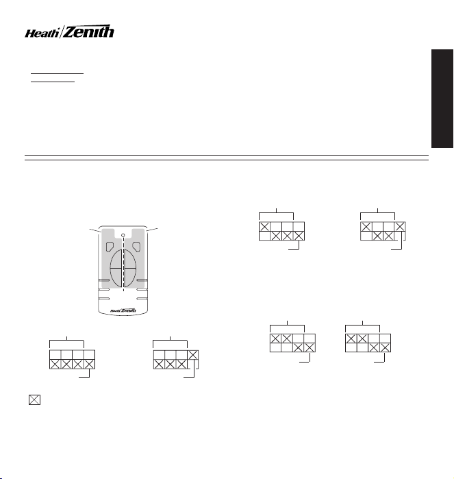
must have the same code and group setting to work together. Switches 1 through 3 set the code. Switch 4 sets the
Group (A or B). See page 2 for switch locations.
Device A Controls:
Controls One Set of
Group “A” or Group
“B” Receiver(s)
Receiver(s)
Code
• Receivers
– Indoor Plug-In Converter
– Floodlight
– Lamp Socket Converter
CODE SETTINGS
AB
DIM
DIM
ON
ON
OFF
OFF
Device B Controls:
Controls One Set of
Group “A” or Group
“B” Receiver(s)
Receiver(s)
Code
• Products are UL/cUL and/or FCC/IC tested and approved.
• Operational range of up to 100 feet.
Heath®/Zenith wireless lighting controls are designed to work
together. Simply determine which transmitter(s) you would
like to have control which receiver(s) and set the code setting
to match.
Note:
When operating more than one system independently of
each other, set each system to a different code. There are 8 codes
available by changing the settings of switches 1 through 3.
Receiver(s)
Group A Group B
Example 2 - Code Switch Settings, System 2
When using a single group transmitter (
A-Switch, Remote Motion Sensor) the code and group settings
must match receiver(s) for the system to function properly.
Code
Receiver(s)
Code
FEATURES
Remote Motion
Sensor Code
Receiver(s)
Code
i.e.
Door Transmitter, Add-
ENGLISH
Group A
(– Indicates Position of Switch)
Example 1 - Code Switch Settings, System 1
DRAFT COPY
(Factory Setting)
Group B
Group A
Note:
This setting will work independently of examples 1 and 2
because the code setting is different.
Example 3 - Code Switch Settings with Single Transmitter
Note:
The channel can also be changed to reduce interference
problems from other wireless products (
garage door openers, etc.). See
information.
Group A
i.e.
wireless phones,
Troubleshooting Guide
for more
© 2004 DESA Specialty Products™ 598-1116-08
DIM
1 2 3 4
ON
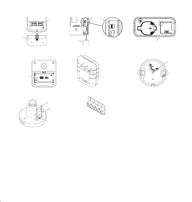
Device A
Code
Switches
Battery
Cover
Code
Switches
ON DIP
ON DIP
1 2 3 4
1 2 3 4
Remote Control
NIGHT
1234
CODES
DAY
DETECT
Device B
Switches
NIGHT
ONL
Y
CODE SWITCH LOCATIONS
1 2 3 4
Access
Door
ON
m
u
B
i
h
a
t
i
t
t
L
e
r
V
y
3
2032
Add-A-Switch
Code
Code
Switches
O
N
1
2
3
4
Code
Switches
3 VOLTS
CR2032
Code Switches
Entry Switch
ON
1 2 3 4
Code
Switches
Wireless Motion Sensor
Lamp Socket Converter
Indoor Plug-In Converter
Floodlight
ON
Screw
Cover
1 2
3 4
Code
Switches
Note:
1 2 3 4
The “X” has been placed on the
switches to help clarify the code
settings on the previous page.
Close-Up of Typical Code Switch
(Factory Default Setting is Off)
DRAFT COPY
2
598-1116-08
Note:
One remote control is able to independently
operate two receiver units set on the same channel. If
more than two receiver units, operating independently,
are desired, additional remote controls will need to be
purchased.
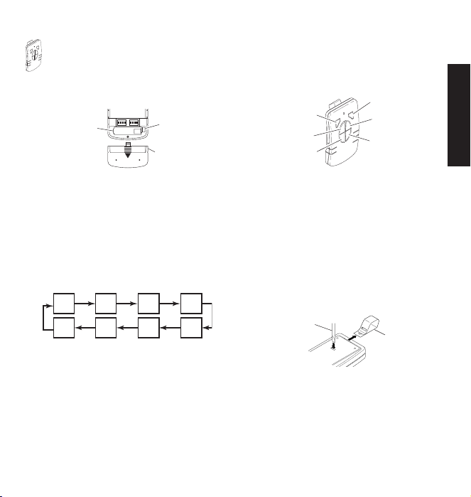
1. Remove Tab from Battery Chamber. Remove cover from
back of transmitter. Gently pull tab out of battery chamber.
Slide cover onto transmitter.
ON DIP
ON DIP
1 2 3 4
1 2 3 4
Battery
Chamber
(Type A23)
2. Remote Control Functions. The three buttons on the left side
• Device A/B ON: Turns on any receiver unit set to the same
channel as this remote control.
• Device A/B OFF: Turns off any receiver unit set to the same
channel as this remote control.
• Device A/B DIM: Activates the DIM feature for any receiver unit
set to the same channel as this remote control.
the DIM button steps through five brightness levels.
Rear View of Remote Control
of the remote will operate one or more receiver units with
matching addresses. The three buttons on the right side of
the remote will operate a second set of one or more receiver
units.
Tab
Battery
Cover
Note:
Pressing
4543
1232
DRAFT COPY
REMOTE CONTROL
Note:
To independently operate a second receiver unit using a
single remote control, make sure the second set of code switches
(Device B) and the code switches on each receiver match (see
Code Settings
• Device A - Set Device A code switches.
• Device B - Set Device B code switches.
Important: Wait 1 to 2 seconds after you press a transmitter
button before you press it again to allow the transmission to be
completed.
Note:
transmitter buttons are pushed, see
The remote control includes an optional car visor clip for added
convenience that may be installed.
1. To attach car visor clip to remote control (if desired) push it
2. To remove car visor clip, insert a small, flat-head screwdriver
section).
Device A DIM
Device A ON
Device A OFF
Function Controls
If light does not turn on or intermittently turns on and off when
Device B DIM
Device B ON
Device B OFF
Troubleshooting Guide
.
Optional Car Visor Clip (Included)
into slot on rear of remote unit until it snaps into place.
into slot on back of remote. Gently push down on portion of
visor clip inside slot with screwdriver while pulling clip out of
remote from top.
Flat-Head
Screwdriver
Removing Visor Clip - Rear View
Optional
Visor Clip
ENGLISH
598-1116-08
3
 Loading...