

Models:
SL-750TRS-IPI-D
SL-550TRS-IPI-D
SL-350TRS-C
Owner’s Manual
Installation and Operation
CAUTION
DO NOT DISCARD THIS MANUAL
Important operating and
•
maintenance instructions included.
WARNING: If the information in these
instructions is not followed exactly , a fire
or explosion may result causing property damage, personal injury , or death.
• Do not store or use gasoline or other flammable vapors and liquids in the vicinity of this or
any other appliance.
• What to do if you smell gas
- Do not try to light any appliance
- Do not touch any electrical switch. Do not
use any phone in your building.
- Immediately call your gas supplier from a
neighbor’s phone. Follow the gas supplier’s
instructions.
- If you cannot reach your gas supplier, call
the fire department.
Read, understand and follow
••
these instructions for safe
installation and operation.
DO NODO NO
DO NO
DO NODO NO
DISCARDDISCARD
DISCARD
DISCARDDISCARD
TT
T
Leave this manual with
party responsible for
use and operation.
TT
W ARNING
HOT! DO NOT TOUCH.
SEVERE BURNS MA Y RESUL T .
CLOTHING IGNITION MA Y RESUL T .
Glass and other surfaces are hot during
operation and cool down.
• Keep children away.
• CAREFULLY SUPERVISE children in same room as
appliance.
• Alert children and adults to hazards of high
temperatures.
• Do NOT operate with protective barriers open or
removed.
• Keep clothing, furniture, draperies and other
combustibles away.
This appliance has been supplied with an integral barrier
to prevent direct contact with the fixed glass panel. Do
NOT operate the appliance with the barrier removed.
Contact your dealer or Hearth & Home Technologies if the
barrier is not present or help is needed to properly install one.
• Installation and service must be performed by
a qualified installer , service agency , or the gas
supplier .
This appliance may be installed as an OEM installation in
manufactured home (USA only) or mobile home and must
be installed in accordance with the manufacturer’s instructions and the manufactured home construction and safety
standard, Title 24 CFR, Part 3280 or Standard for Installa-
tion in Mobile Homes, CAN/CSA Z240MH.
This appliance is only for use with the type(s) of gas indi-
cated on the rating plate.
Heat & Glo • SL-350TRS-C, SL-550/750TRS-IPI-D • 2065-985 Rev. J • 5/06
In the Commonwealth of Massachusetts:
• installation must be performed by a licensed plumber or
gas fitter;
See Table of Contents for location of additional
Commonwealth of Massachusetts requirements.
Installation and service of this appliance should be
performed by qualified personnel. Hearth & Home
T echnologies suggests NFI certified or factory -trained
professionals, or technicians supervised
by an NFI certified professional.
Í
1
SAFETY AND WARNING INFORMATION
READ and UNDERSTAND all instructions carefully
!
before starting the installation. FAILURE TO
FOLLOW these installation instructions may result
in a possible fire hazard and will void the warranty.
Prior to the first firing of the appliance, READ the
!
Using Your Appliance section of the Owners Guide.
DO NOT USE this appliance if any part has been
!
under water. Immediately CALL a qualified service
technician to inspect the unit and to replace any part
of the control system and any gas control which has
been under water.
THIS UNIT IS NOT FOR USE WITH SOLID FUEL.
!
Installation and repair should be PERFORMED by a
qualified service person. The appliance and venting
!
system should be INSPECTED before initial use
and at least annually by a professional service
person. More frequent cleaning may be required
due to excessive lint from carpeting, bedding
material, etc. It is IMPERATIVE that the unit’s
control compartment, burners, and circulating air
passageways
adequate combustion and ventilation air.
BE KEPT CLEAN to provide for
These units MUST use one of the vent systems
described in the Installing the Appliance section of
!
the Installers Guide. NO OTHER vent systems or
components MAY BE USED.
This gas appliance and vent assembly MUST be
!
vented directly to the outside and MUST NEVER be
attached to a chimney serving a separate solid fuel
burning appliance. Each gas appliance MUST USE
a separate vent system. Common vent systems are
PROHIBITED.
INSPECT the external vent cap on a regular basis to
!
make sure that no debris is interfering with the air
flow.
The glass door assembly MUST be in place and
!
sealed, and the trim door assembly MUST be in
place on the appliance before the unit can be
placed into safe operation.
DO NOT OPERATE this appliance with the glass
!
door removed, cracked, or broken. Replacement of
the glass door should be performed by a licensed
or qualified service person. DO NOT strike or slam
the glass door.
Always KEEP the appliance clear and free from
!
combustible materials, gasoline, and other
flammable vapors and liquids.
NEVER OBSTRUCT the flow of combustion and
!
ventilation air. Keep the front of the appliance
CLEAR of all obstacles and materials for servicing
and proper operations.
Due to the high temperature, the appliance should
be LOCATED out of traffic areas and away from
!
furniture and draperies. Clothing or flammable
material SHOULD NOT BE PLACED on or near the
appliance.
Children and adults should be ALERTED to the
!
hazards of high surface temperature and should
STAY AWAY to avoid burns or clothing ignition.
Y oung children should be CAREFULL Y SUPERVISED
when they are in the same room as the appliance.
The glass door assembly SHALL ONLY be
!
replaced as a complete unit, as supplied by the gas
appliance manufacturer. NO SUBSTITUTE material
may be used.
DO NOT USE abrasive cleaners on the glass door
!
assembly. DO NOT ATTEMPT to clean the glass
door when it is hot.
Turn off the gas before servicing this appliance. It is
recommended that a qualified service technician
!
perform an appliance check-up at the beginning of
each heating season.
Any safety screen or guard removed for servicing
!
must be replaced before operating this appliance.
DO NOT place furniture or any other combustible
!
household objects within 36 inches of the
appliance front.
2
Heat & Glo • SL-350TRS-C, SL-550/750TRS-IPI-D • 2065-985 Rev. J • 5/06

TABLE OF CONTENTS
Safety and Warning Information ......................................................... 2
Service Parts Lists................................................................................. 4
Î
Section 1: Approvals and Codes........................................................ 12
Appliance Certification ........................................................................... 12
Installation Codes .................................................................................. 12
High Altitude Installations ...................................................................... 1 2
Requirements for the Commonwealth of Massachusetts........................ 13
Î
Section 2: Getting Started .................................................................. 14
Introducing the Heat & Glo Gas Appliances ........................................... 14
Pre-installation Preparation.................................................................... 14
Section 3: Installing the Appliance ................................................... 18
Constructing the Appliance Chase ......................................................... 18
Step 1 Locating the Appliance.......................................................... 18
Step 2 Framing the Appliance .......................................................... 19
Step 3 Installing the Vent System.................................................... 22
A. Vent System Approvals ................................................... 22
B. Installing Vent Components............................................. 32
C. Vent Termination.............................................................. 35
Step 4 Positioning, Leveling, and
Securing the Appliance ......................................................... 38
Step 5 The Gas Control Systems..................................................... 38
Step 6 The Gas Supply Line............................................................. 39
Step 7 Gas Pressure Requirements................................................. 39
Step 8 Wiring the Appliance ............................................................. 40
Step 9 Finishing ............................................................................... 42
Step 10 Installing Trim, Logs, and Ember Material ............................. 43
Installing the Trim.................................................................. 43
Positioning the Logs ............................................................. 43
Shutter Settings.................................................................... 43
Placing the Ember Material................................................... 43
Glass Specifications ............................................................. 43
Step 1 1 Before Lighting the Appliance................................................ 44
Step 12 Lighting the Appliance ........................................................... 44
After the Installation ............................................................................... 44
Section 4: Maintaining and Servicing Your Appliance................... 45
Î = Contains updated information.
Heat & Glo • SL-350TRS-C, SL-550/750TRS-IPI-D • 2065-985 Rev. J • 5/06
3
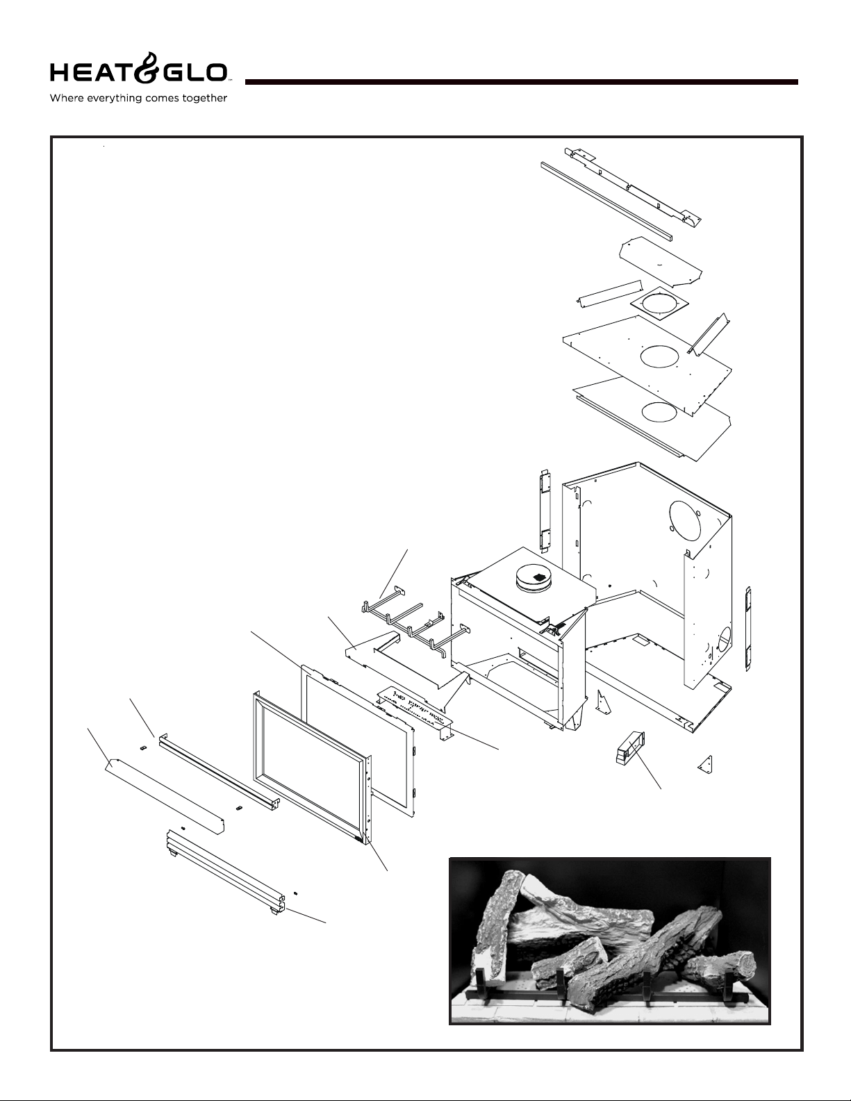
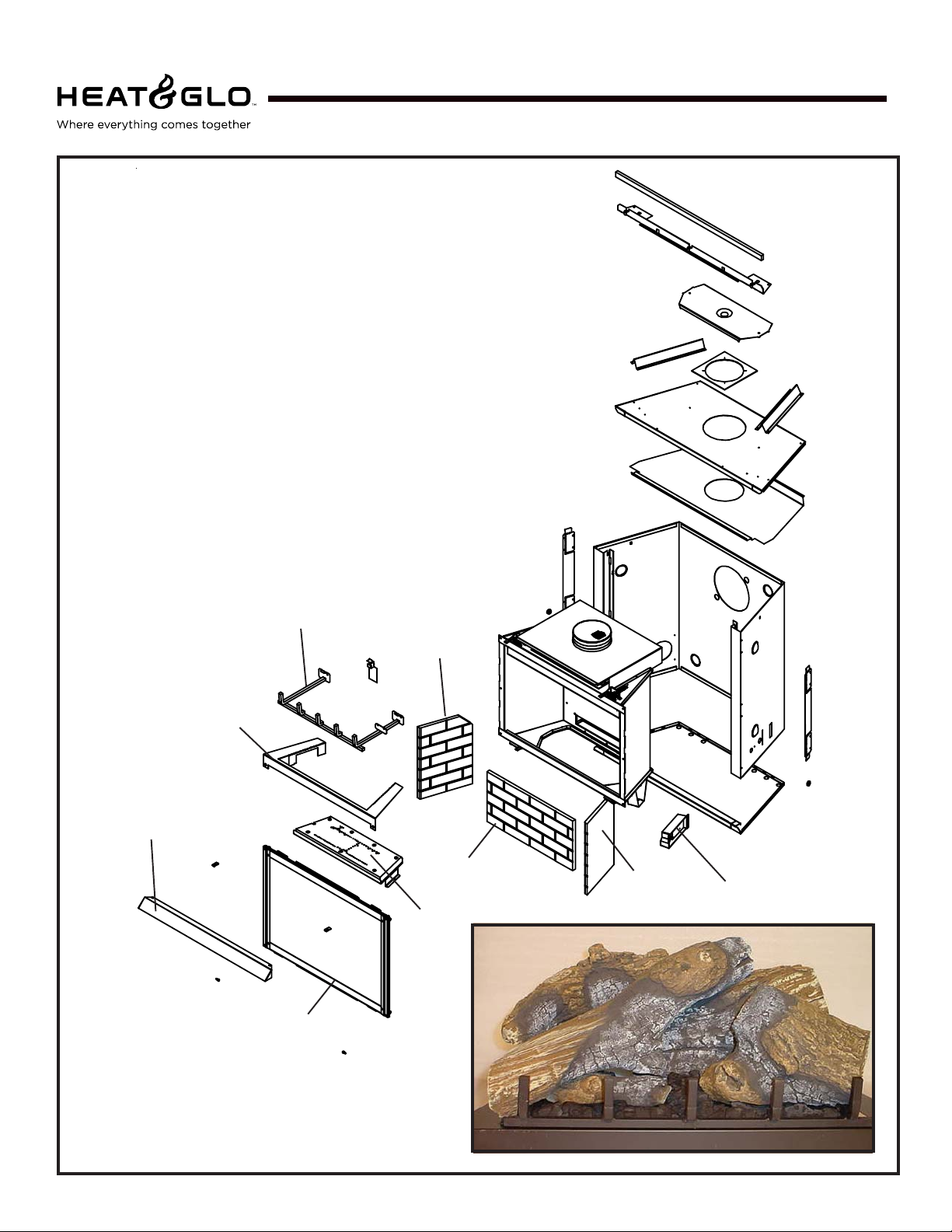
Service Parts
SL-350TRS-C
(NG , LP) Exploded Parts Diagram
Beginning Manufacturing Date: 4-01
Ending Manufacturing Date: ______
4
5
1
14
6
2
13
7 Log Set Assembly
3
15
12
8
11
10
9
Part number list on following page.
4
Heat & Glo • SL-350TRS-C, SL-550/750TRS-IPI-D • 2065-985 Rev. J • 5/06
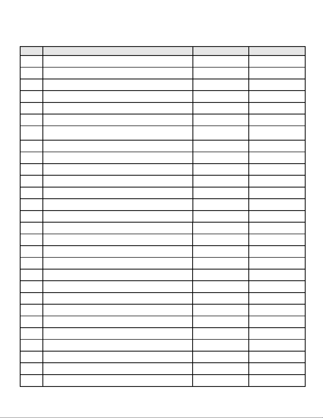
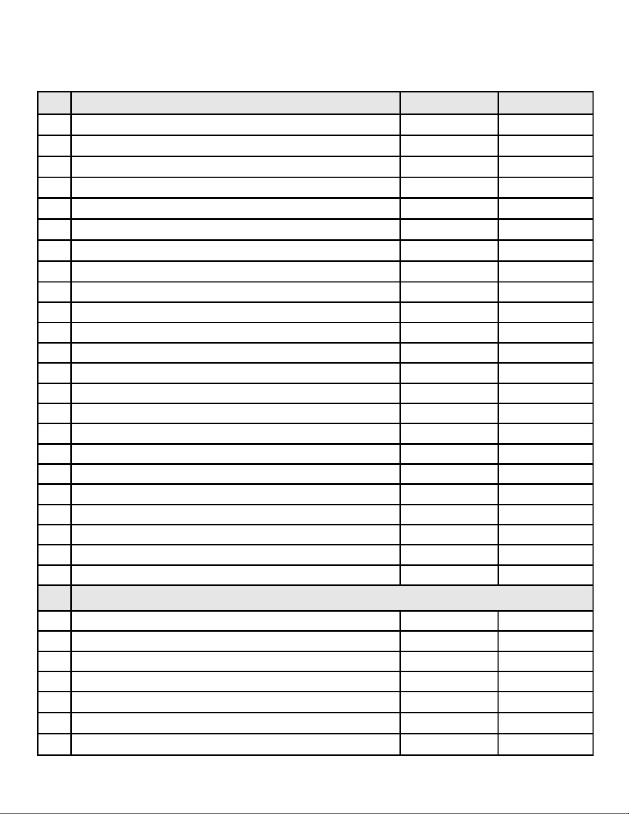
(NG , LP) Service Part s List
SL-350TRS-C
IMPORT ANT: THIS IS DATED INFORMA TION. The most current information is located on your dealers VIP site. When order-
ing, supply serial and model numbers to ensure correct service parts.
ITEM STANDING PILOT SERIAL # PART NUMBER
Burner Orifice NG (#43C) 582-843
Burner Orifice LP (#53C ) 582-853
1 Glass Door Assembly GLA-350TRS
2Burner NG, LP 540-234A
3 Mesh Panel Door 540-382A
4 Log Grate 540-361A
5 B ase Refractory
PRE 4/06
POST 4/06
540-206T (Tan)
2065-206 (Black)
6 Hood SRV540-174
7 Log S et Assembly LOGS-350
8 Log 1 SRV530-701
9 Log 2 SRV530-704
10 Log 3 SRV540-702
11 Log 4 SRV530-705
12 Log 5 SRV530-703
13 Junction Box
PRE 00251404
POST 00251404
100-250A
4021-013
14 Louver, Top 540-256A
15 Louver, B ottom 540-257A
Pilot Orifice NG 446-505
Pilot Orifice LP 446-517
Thermocouple 446-511
Thermopile 060-512
Conversion Kit NG NGK-350TRS-C
Conversion Kit LP LPK-350TRS-C
Vermiculite Embers MYSTIC-EMBERS
E xhaust R estrictor 530-299
Glass Latch Assembly 386-122A
Mineral Wool 050-721
To uch up Paint TUP-GBK-12
Also see additional pages for valve assembly service part numbers.
Heat & Glo • SL-350TRS-C, SL-550/750TRS-IPI-D • 2065-985 Rev. J • 5/06
5
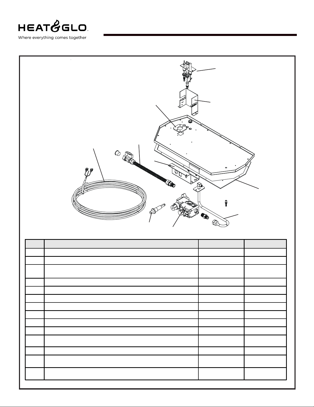
Service Parts
SL-350TRS-C
Standing Pilot Ignition
Valve Assembly
3
(NG , LP) Exploded Parts Diagram
2
7
5
Beginning Manufacturing Date: 4-01
Ending Manufacturing Date: ______
4
10
6
9
1
ITEM DESCRIPTION SERIAL # PART NUMBER
1Piezo Ignitor 291-513
2 Burner Neck Gasket 2045-407
3 Thermostat Wire Assembly
4 Pilot Assembly NG 530-510A
4 Pilot Assembly LP 530-511A
5 Valve Bracket 2025-101
6 Valve Plate Gasket 530-431
7 Flex Ball Valve Assembly 302-320A
8Valve NG 060-522
8 Valve LP 060-523
9 Flexible Gas Connector
10 Pilot Bracket 530-164
ON/OFF Rocker Sw itch
Wire Assembly
8
PRE 00251404
POST 00251404
PRE 22099930
POST 22099930
PRE 00251404
POST 00251404
PRE 00251404
POST 00251404
N/A
2045-024
567-301A
530-302A
060-511
N/A
049-552A
N/A
6
Heat & Glo • SL-350TRS-C, SL-550/750TRS-IPI-D • 2065-985 Rev. J • 5/06
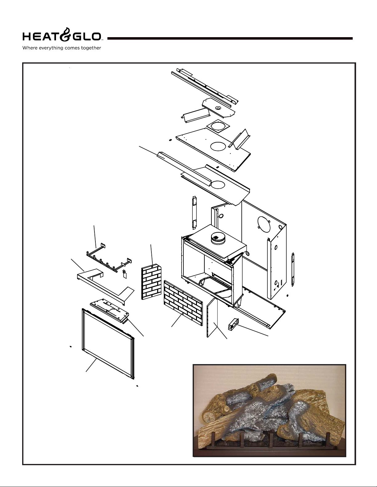
Service Parts
SL-550TRS-IPI-D
Î
(NG , LP) Exploded Parts Diagram
Beginning Manufacturing Date: 4-04
Ending Manufacturing Date: ______
4
14
5
6
13
15
1
7 Log Set Assembly
2
12
3
11
9
10
Part number list on following page.
Heat & Glo • SL-350TRS-C, SL-550/750TRS-IPI-D • 2065-985 Rev. J • 5/06
8
7
(NG, LP) Service Parts List
SL-550TRS-IPI-D
IMPORTANT : THIS IS DATED INFORMA TION. The most current information is located on your dealers VIP site. When ordering,
supply serial and model numbers to ensure correct service parts.
ITEM DESCRIPTION SERIAL # PART NUMBER
Burner Orifice NG (#38C) 582-838
Burner Orifice LP (#53C) 582-853
1 Junc tio n Box 4021-013
2Burner NG 2065-005
2Burner LP 2065-006
3 Glass Door Assembly GLA-550TRS
4 Log Grate 2066-036
5 Base Refractory NG, LP 2065-100
6 Hood SRV550-175
7 Log Set Assembly LOGS-550TRS-D
8 Log 1 SRV2065-701
9 Log 2 SRV2065-702
10 Log 3 SRV2065-703
11 Log 4 SRV2065-704
12 Log 5 SRV2065-705
Refr ac tory K it BRICK-550TRS -D
13 Refractory, Back SRV2044-711
14 Refractory, Left Side SRV 2044-710
15 Refractory, Right Side SRV2044-712
Pilot Orifice NG 446-505
Pilot Orifice LP 446-517
Thermocouple 446-511
Thermopile 060-512
Mineral Wool 050-721
Glass Latch 386-122A
Exhaust Restrictor 530-299
To uc h up Paint TUP-GBK-12
ACCESSOR IES
Fan K it GFK-160A
Extended Vertical Baffle Kit BAF-VERT
Í
Í
Í
Wall Switch Kit, Off-white WSK-21
Wall Switch Kit, White WSK-21-W
Conversion K i t NG NGK-550TRS-IPID
Conversion K i t LP LPK-550TRS-IPID
Vermiculi te Embers MYSTIC-EMBERS
Also see additional pages for valve assembly service part numbers.
8
Heat & Glo • SL-350TRS-C, SL-550/750TRS-IPI-D • 2065-985 Rev. J • 5/06
Service Parts
SL-750TRS-IPI-D
Î
(NG , LP) Exploded Parts Diagram
6
4
Beginning Manufacturing Date: 4-04
Ending Manufacturing Date: ______
14
5
2
15
13
1
7 Log Set Assembly
3
12
9
Part number list on following page.
Heat & Glo • SL-350TRS-C, SL-550/750TRS-IPI-D • 2065-985 Rev. J • 5/06
11
10
8
9
(NG, LP) Service Parts List
SL-750TRS-IPI-D
IMPORTANT: THIS IS DA TED INFORMATION. The most current information is located on your dealers VIP site. When order-
ing, supply serial and model numbers to ensure correct service parts.
ITEM DESCRIPTION SERIAL # PART NUMBER
Burner Orifice NG (#36C) 582-836
Burner Orifice LP (#52C) 582-852
1 J un ct io n Bo x 4021-013
2 Burne r NG 2066-005
2 Burne r L P 2065-006
3 Glass Door Assembly GLA-750TRS
4 Log Grate 2066-036
5 Base Refractory NG, LP 2066-100
6 Hood SRV530-175
7 Log Set Assembly LOGS-750TRS-D
8 Log 1 SRV2065-701
9 Log 2 SRV2066-702
10 Log 3 SRV2066-703
11 Log 4 SRV2066-704
12 Log 5 SRV2066-705
Refrac to ry K it B RIC K -750TRS-D
13 Refra c tory, Back SRV2045-711
14 Refractory, Left Side SRV2045-710
15 Refra c tory, Right S ide SRV2045-712
Mineral Wool 050-721
Glass Latch Assembly 386-122A
Exhaust Restrictor 530-299
Touch up Paint TUP-GBK-12
ACCESSORIES
Fan Kit GFK-160A
Extended Vertical Baffle Kit B A F-VERT
Í
Í
Í
Wall S witch Kit, Off-white WSK-21
Wall Switch Kit, White WSK-21-W
Conversion Kit NG NGK-750TRS-IPI D
Conversion Kit LP LPK-750TRS-IPID
Vermiculite E mbers MYSTIC-EMBERS
Also see additional pages for valve assembly service part numbers.
10
Heat & Glo • SL-350TRS-C, SL-550/750TRS-IPI-D • 2065-985 Rev. J • 5/06
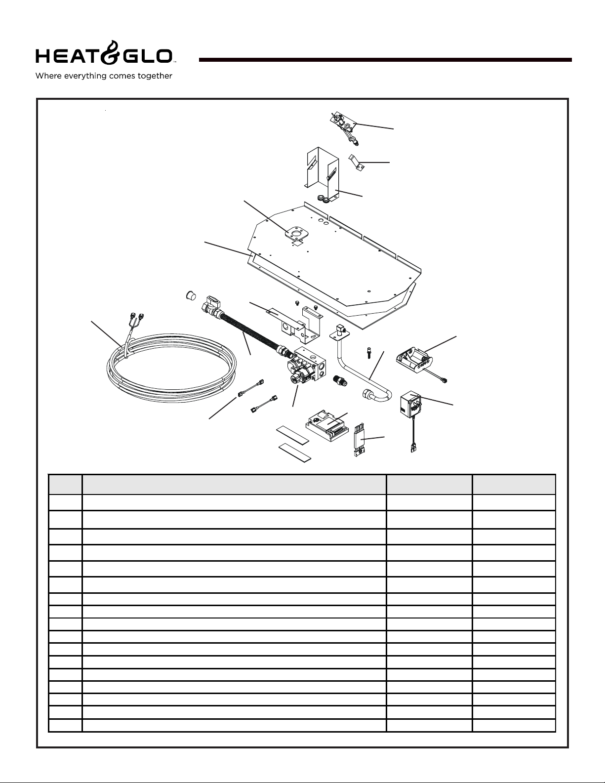
Service Parts
SL-750TRS-IPI-D, SL-550TRS-IPI-D
Intermittent Pilot Ignition
Valve Assembly
14
2
(NG , LP) Exploded Parts Diagram
1
5
7
Beginning Manufacturing Date: 4-04
Ending Manufacturing Date: ______
4
6
15
12
9
3
8
10
13
11
ITEM /
PIÈCE
1 Burner Neck Gasket / Jo i nt de Cou de Brûleur 2045-407
2 Thermostat Wire Assembly / L'Assemblée de Fi l de thermostat 2045-024
3 Wi re A s s e mb ly / Module de fil 2012-206
4 Pilot Assembly NG / Module de veilleuse GN 4021-025
4 Pilot Assembly LP / Module de veilleuse P L 4021-026
5 Valve Bracket / Parenthèse de Valve 2025-101
6 Ground Strap / Courro ie d e Raison(Terre ) 385-512
7 Flex Ball Valve Assembly / Fléchir l'Assemblée de Soupape de Balle 302-320A
8Valve NG / Valve GN 750-500
8 Valve LP / Valve PL 750-501
9 Flexible Gas Connector / Tuyau à gaz flexible 530-302A
10 Module / Module 593-592
11 Wire A s s e mb ly / Module d e fi l 593-590A
12 Battery Pack / Pa quet de Batterie(Pile) 593-594A
13 3 Volt Transformer / 3 Transforma teur de Volt 593-593A
14 Valve Plate Gasket / Joint de P lat de Valve 530-431
15 Pilot Bracket / Parenthèse Pilote 2065-117
DESCRIPTION
SERIAL #
/ N° DE SÉRIE
PART N UMBE R
/ N° D E PIÈC E
Heat & Glo • SL-350TRS-C, SL-550/750TRS-IPI-D • 2065-985 Rev. J • 5/06
11
1
Approvals and
Codes
Appliance Certification
The Heat & Glo appliance models discussed in this Installers
Guide have been tested to certification standards and listed
by the applicable laboratories.
Certification
MODELS: SL-750TRS-IPI-D, SL-550TRS-IPI-D,
SL-350TRS-C
LABORA TORY : Underwriters Laboratories
TYPE: Direct Vent Gas Fireplace Heater
STANDARD: ANSI Z21.88•CSA2.33•UL307B
NOTE: THESE MODELS ARE UL LISTED TO UL307B,
THE ST ANDARD FOR GAS-BURNING HEATING APPLIANCES FOR MANUFACTURED HOMES AND RECREA TIONAL VEHICLES.
Installation Codes
The appliance installation must conform to local codes.
Before installing the appliance, consult the local building
code agency to ensure that you are in compliance with all
applicable codes, including permits and inspections.
High Altitude Installations
U.L. Listed gas appliances are tested and approved without requiring changes for elevations from 0 to 2,000 feet in
the U. S. A. and in Canada.
When installing this appliance at an elevation above 2,000
feet, it may be necessary to decrease the input rating by
changing the existing burner orifice to a smaller size. Input
rate should be reduced by 4% for each 1000 feet above a
2000 foot elevation in the U.S.A. or 10% for elevations
between 2000 and 4500 feet in Canada. If the heating value
of the gas has been reduced, these rules do not apply . To
identify the proper orifice size, check with the local gas
utility.
If installing this appliance at an elevation above 4,500 feet
(in Canada), check with local authorities.
In the absence of local codes, the appliance installation
must conform to the National Fuel Gas Code ANSI Z223.1
(in the United States) or the CAN/CGA-B149 Installation
Codes (in Canada). The appliance must be electrically
grounded in accordance with local codes or, in the absence
of local codes with the National Electric Code ANSI/NFPA
No. 70 (in the United St ates), or to the CSA C22.1 Canadian
Electric Code (in Canada).
These models may be installed in a bedroom or bed-sitting
room in the U.S.A. and Canada.
Heat & Glo Quality
Systems registered
by SGS ICS
12
Heat & Glo • SL-350TRS-C, SL-550/750TRS-IPI-D • 2065-985 Rev. J • 5/06

NOTE: The following requirements reference various
Massachusetts and national codes not contained in
this document.
Î
Requirements for the Commonwealth of
Massachusetts
For all side wall horizontally vented gas fueled equipment
installed in every dwelling, building or structure used in
whole or in part for residential purposes, including those
owned or operated by the Commonwealth and where the
side wall exhaust vent termination is less than seven (7)
feet above finished grade in the area of the venting, including but not limited to decks and porches, the following requirements shall be satisfied:
Installation of Carbon Monoxide Detectors
At the time of installation of the side wall horizontal vented
gas fueled equipment, the installing plumber or gasfitter
shall observe that a hard wired carbon monoxide detector
with an alarm and battery back-up is installed on the floor
level where the gas equipment is to be installed. In addition, the installing plumber or gasfitter shall observe that a
battery operated or hard wired carbon monoxide detector
with an alarm is installed on each additional level of the
dwelling, building or structure served by the side wall horizontal vented gas fueled equipment. It shall be the responsibility of the property owner to secure the services of qualified licensed professionals for the installation of hard wired
carbon monoxide detectors.
In the event that the side wall horizontally vented gas fueled equipment is installed in a crawl space or an attic, the
hard wired carbon monoxide detector with alarm and battery back-up may be installed on the next adjacent floor
level.
In the event that the requirements of this subdivision can
not be met at the time of completion of installation, the
owner shall have a period of thirty (30) days to comply with
the above requirements; provided, however, that during said
thirty (30) day period, a battery operated carbon monoxide
detector with an alarm shall be installed.
Approved Carbon Monoxide Detectors
Each carbon monoxide detector as required in accordance
with the above provisions shall comply with NFP A 720 and
be ANSI/UL 2034 listed and IAS certified.
Inspection
The state or local gas inspector of the side wall horizontally
vented gas fueled equipment shall not approve the installation unless, upon inspection, the inspector observes carbon
monoxide detectors and signage installed in accordance with
the provisions of 248 CMR 5.08(2)(a)1 through 4.
Exemptions
The following equipment is exempt from 248 CMR 5.08(2)(a)1
through 4:
• The equipment listed in Chapter 10 entitled “Equipment
Not Required To Be Vented” in the most current edition
of NFP A 54 as adopted by the Board; and
• Product Approved side wall horizont ally vented gas fueled equipment installed in a room or structure separate from the dwelling, building or structure used in whole
or in part for residential purposes.
MANUFACTURER REQUIREMENTS
Gas Equipment Venting System Provided
When the manufacturer of Product Approved side wall horizontally vented gas equipment provides a venting system
design or venting system components with the equipment,
the instructions provided by the manufacturer for installation of the equipment and the venting system shall include:
• Detailed instructions for the installation of the venting
system design or the venting system components; and
• A complete parts list for the venting system design or
venting system.
Gas Equipment Venting System NOT Provided
When the manufacturer of a Product Approved side wall
horizontally vented gas fueled equipment does not provide
the parts for venting the flue gases, but identifies “special
venting systems”, the following requirements shall be satisfied by the manufacturer:
• The referenced “special venting system” instructions shall
be included with the appliance or equipment installation
instructions; and
• The “special venting systems” shall be Product Approved
by the Board, and the instructions for that system shall
include a parts list and detailed installation instructions.
Signage
A metal or plastic identification plate shall be permanently
mounted to the exterior of the building at a minimum height
of eight (8) feet above grade directly in line with the exhaust vent terminal for the horizontally vented gas fueled
heating appliance or equipment. The sign shall read, in
print size no less than one-half (1/2) inch in size, “GAS
VENT DIRECTLY BELOW. KEEP CLEAR OF ALL OBSTRUCTIONS”.
Heat & Glo • SL-350TRS-C, SL-550/750TRS-IPI-D • 2065-985 Rev. J • 5/06
A copy of all installation instructions for all Product Approved side wall horizontally vented gas fueled equipment,
all venting instructions, all parts lists for venting instructions, and/or all venting design instructions shall remain
with the appliance or equipment at the completion of the
installation.
See Gas Connection section for additional Commonwealth of Massachusetts requirements.
13

2
Getting Started
Introducing the Heat & Glo Gas Appliances
Heat & Glo direct vent gas appliances are designed to operate with all combustion air siphoned from outside of the
building and all exhaust gases expelled to the outside.
The information contained in this Installers Guide, unless
noted otherwise, applies to all models and gas control
systems. Gas appliance diagrams, including the dimensions,
are shown in this section.
Pre-install Preparation
This gas appliance and its components are tested and safe
when installed in accordance with this Installers Guide.
Report to your dealer any parts damaged in shipment,
particularly the condition of the glass. Do not install any
unit with damaged, incomplete, or substitute parts.
The vent system components and trim doors are shipped
in separate packages. The gas logs are packaged
separately and must be field installed.
Read all of the instructions before starting the
installation. Follow these instructions carefully during
the installation to ensure maximum safety and benefit.
Failure to follow these instructions will void the
owner’s warranty and may present a fire hazard.
The Heat & Glo Warranty will be voided by , and Heat & Glo
disclaims any responsibility for, the following actions:
• Installation of any damaged appliance or vent system
component.
• Modification of the appliance or direct vent system.
• Installation other than as instructed by Heat & Glo.
• Improper positioning of the gas logs or the glass door.
• Installation and/or use of any component part not manu-
factured and approved by Heat & Glo, not withstanding
any independent testing laboratory or other party approval
of such component part or accessory .
ANY SUCH ACTION MAY POSSIBLY CAUSE A FIRE
HAZARD.
When planning a appliance installation, it’s necessary to
determine:
• Where the unit is to be installed.
• The vent system configuration to be used.
• Gas supply piping.
• Electrical wiring.
• Framing and finishing details.
• Whether optional accessories—devices such as a fan,
wall switch, or remote control—are desired.
If the appliance is to be installed on carpeting or tile, or on
any combustible material other than wood flooring, the
appliance should be installed on a metal or wood panel that
extends the full width and depth of the appliance.
14
Heat & Glo • SL-350TRS-C, SL-550/750TRS-IPI-D • 2065-985 Rev. J • 5/06

15-3/8
391[]
30-3/4
781[]
1/2
13[]
40
1016[]
GASS LIN E
ACCESS
2-1/4
57[]
6
152[]
15-7/8
403[]
35-5/8
905[]
ø6-5/8
36-1/8
918[]
41
1041.4[]
8-3/4
168.3[]
5-1/2
140[]
6-7/8
175[]
222[]
3-9/16
[]
90
16-1/4
413[]
37-7/8
962[]
ELECTRICAL
ACCESS
GAS LINE
ACCESS
GAS
CONTROLS
Figure 1. Diagram of the SL-750TRS-IPI-D
TOP STANDOFFS
HOOD
CERAMIC
FIBER PAD
RATING PLATES
& LABELS
BOTT OM GRI L L E
COVER
VENT COLLARS
ELECTRICAL
ACCESS
Heat & Glo • SL-350TRS-C, SL-550/750TRS-IPI-D • 2065-985 Rev. J • 5/06
15

12-7/8
S
327[
25-3/4
654[
]
]
]
13[
1/2
35-7/16
900.1[
GAS LINE
]
ACCESS
2-1/8
54[
15-7/8
403[
]
6
152[]
]
32-1/8
816[
16-1/4
]
413[
]
]
168.3[
ø 8
ø6-5/8
[
168.3
8-13/16
224[
]
5-1/2
]
140[
]
3-1/2
[
90
]
32-9/16
[]
827
ELECTRICAL
31-1/8
791[]
6-7/8
174[]
ACCESS
36
914[]
GAS LINE
ACCESS
GAS
CONTROLS
Figure 2. Diagram of the SL-550TRS-IPI-D
TOP STANDOFF
HOOD
CERAMIC
FIBER PAD
RATING PLATES
& LABELS
BOTTOM GR I L L E
COVER
VENT COLL ARS
ELECTRICAL
ACCESS
16
Heat & Glo • SL-350TRS-C, SL-550/750TRS-IPI-D • 2065-985 Rev. J • 5/06

11-3/8
289[]
22-3/4 577[]
1/2
13[]
34-1/2
876[]
GAS LINE
ACCESS
15-7/8
ø6-5/8
2-1/8
55[]
402[]
168.3[]
30-1/2
776[]
6
153[]
28-1/8
714[]
33
836[]
8-3/4
223[]
15-1/4
388[]
16-1/4
413[]
3-1/2
29
737[]
6-7/8
174[]
90[]
ø8 [203]
30-5/8
777[]
21-1/4
540[]
ELECTRICAL
ACCESS
GAS LINE
ACCESS
GAS
CONTROLS
TOP STANDOFFS
HOOD
CERAMIC
FIBER PAD
RATING PLATES
& LABELS
BOTTOM GRILLE
COVER
VENT COLLARS
ELECTRICAL
ACCESS
Figure 3. Diagram of the SL-350TRS-C
Heat & Glo • SL-350TRS-C, SL-550/750TRS-IPI-D • 2065-985 Rev. J • 5/06
17

3” MIN. (76mm)
B
Installing the Appliance
3
Constructing the Appliance Chase
A chase is a vertical box-like structure built to enclose the
gas appliance and/or its vent system. V ertical vents that run
on the outside of a building may be, but are not required to
be, installed inside a chase.
CAUTION: TREA TMENT OF FIREST OP SPACERS AND
CONSTRUCTION OF THE CHASE MA Y V ARY WITH THE
TYPE OF BUILDING. THESE INSTRUCTIONS ARE NOT
SUBSTITUTES FOR THE REQUIREMENTS OF LOCAL
BUILDING CODES. THEREFORE, YOUR LOCAL BUILDING CODES MUST BE CHECKED TO DETERMINE THE
REQUIREMENTS FOR THESE STEPS.
Factory-built appliance chases should be constructed in
the manner of all outside walls of the home to prevent cold
air drafting problems. The chase should not break the outside building envelope in any manner.
This means that the walls, ceiling, base plate and cantilever
floor of the chase should be insulated. V apor and air infiltration barriers should be installed in the chase as per regional
codes for the rest of the home. Additionally , in regions where
cold air infiltration may be an issue, the inside surfaces
may be sheetrocked and taped for maximum air tightness.
T o further prevent draft s, the firestops should be caulked to
seal gaps. Gas line holes and other openings should be
caulked or stuffed with insulation. If the unit is being installed on a cement slab, a layer of plywood may be placed
underneath to prevent conducting cold up into the room.
A
E
C
1/2 “ MIN. (13mm)
MODEL VENT A B C D E
SL-750TRS-IPI-D
SL-550TRS-IPI-D
SL-350TRS-C
*NOTE: If venting with (2) 900 elbows off rear of unit
the dimensions C, D, and E, will change.
Figure 4. Appliance Dimensions, Locations,
and Space Requirements
from the Appliance to Combustible Materials
Glass Front..........................................36.... 914
Floor .....................................................0....... 0
Rear .................................................... 1/2 .... 13
Sides .................................................. 1/2 .... 13
*T op (SL-750TRS-IPI-D) ..........................................3 1/4 ... 83
(SL-550TRS-IPI-D, SL-350TRS-C) ...................1 1/2... 38
Ceiling**............................................... 31 .... 787
Top 42 16-1/4 31-7/8 45 63-3/4
Rear 42 16-1/4 36-5/8 52 73-1/4
*
Top 37 16-1/4 29-3/8 41-1/2 58-3/4
Rear 37 16-1/4 34-1/8 48-1/2 68-1/4
*
Top 34 16-1/4 27-7/8 39-3/8 55-5/8
Rear 34 16-1/4 32-5/8 46-3/8 65-1/8
*
Minimum Clearances
Inches mm
D
THE CHASE SHOULD BE CONSTRUCTED SO THA T ALL
CLEARANCES TO THE APPLIANCE ARE MAINT AINED
AS SPECIFIED WITHIN THIS INST ALLERS GUIDE.
Step 1. Locating the Appliance
Sp ace and clearance requirements for locating a appliance
within a room (see Figure 4).
Clearance Requirements
The top and back of the appliance are defined by standoffs. The minimum clearance to a perpendicular wall
extending past the face of the appliance is 3 inches (76mm).
The back of the appliance may be recessed 16 1/4 inches
(413mm) into combustible construction.
The distance from the unit to combustible construction is to
be measured from the unit outer wrap surface to the combustible construction, NOT from the screw heads that secure the unit together.
18
Heat & Glo • SL-350TRS-C, SL-550/750TRS-IPI-D • 2065-985 Rev. J • 5/06
* The clearance to the ceiling is measured from the top
of the unit, excluding the standoffs (see Figure 37).
Minimum Clearances
from the Vent Pipe to Combustible Materials
Inches mm
Vertical Sections. ............. 1 ................ 25
Horizontal Sections
Top ..................................... 3 ................ 75
Bottom ............................... 1 ................ 25
Sides ................................. 1 ................ 25
At Wall Firestops
To p.................................. 2 1/2 ............63.7
Bottom ..............................1/2............... 13
Sides ................................. 1 ................ 25
For minimum clearances, see the direct vent termination
clearance diagrams in Figures 29 and 30 in this manual.

Step 2. Framing the Appliance
Appliance framing can be built before or after the appliance
is set in place. Framing should be positioned to accommodate wall coverings and appliance facing material. The diagram below shows framing reference dimensions.
VENT
FRAMING
HOLE
*The center of the
framing hole is one (1)
inch (25.4mm) above
the center of the horizontal vent pipe.
*
D
E
CAUTION: MEASURE APPLIANCE DIMENSIONS AND
VERIFY FRAMING METHODS AND WALL COVERING
DET AILS BEFORE FRAMING .
The framing headers
may rest on the
appliance stand-offs.
B
Framing should be
constructed of 2 X 4
lumber or heavier.
Models A B C D E
SL-750TRS-IPI-D 42” 38 1/4” 16 1/4” 41” 27 7/8”
SL-550TRS-IPI-D 37” 33” 16 1/4” 36 1/2” 24 3/8”
SL-350TRS-C 34” 31” 16 1/4” 35 1/2” 22 3/8”
WALL STUD
2-1/4”
C
A
3”
NON-COMBUSTIBLE ZONE
IS DEFINED BY 3” ABOVE THE
ELBOW FOR THE ENTI RE
WIDTH AND DEPTH (BEHIND THE
FRO NT HEADER) OF THE FIREBOX.
Figure 5. Framing Dimensions
Heat & Glo • SL-350TRS-C, SL-550/750TRS-IPI-D • 2065-985 Rev. J • 5/06
19

12-3/16
MAX.
DVP12
12
2
MIN.
6
4
DVP4
DVP6
14-1/4
24
9-7/8
DVP12A
10-1/4
DVP45
45.0
36
48
O
DVP24
DVP36
11-1/4
7-1/4
1-1/4 TYP
DVP48
1/2 TYP
NOTE: PIPES OVERLAP 1-1/4 INCHES
(34.93mm) A T EACH JOINT.
12-9/16
V
P
D
0
9
8-9/16
S
T
Figure 6. DVP-Series Direct Vent Component S pecifications (5-inch inner pipe / 8-inch outer pipe)
20
Heat & Glo • SL-350TRS-C, SL-550/750TRS-IPI-D • 2065-985 Rev. J • 5/06

9 1/4
6 5/8
6 1/2
6 3/8
6 3/8
6 1/2
9 5/8
8 3/4
17-24
SL-09D
SL-45D
SL-12/17D (SL12-17D)
12-17
23 3/4
6 5/8
SL-24D
SL-90D
35 3/4
9 5/8
SL-36D
SL-48D
47 3/4
SL-17/24D
(SL17-24D)
SL-FLEX-10
SL-FLEX-5
SL-FLEX-3
36”
(914mm)
11 3/4
60”
(1524mm)
SL-12D
120”
(3048mm)
5 3/4
SL-06D
6 1/2
6 5/8
SL-FLEX-2
24”
(610mm)
NOTE: PIPES OVERLAP 1-3/8 INCHES
(34.93mm) A T EACH JOINT.
Figure 7. SL D-Series Direct Vent Component Specifications (4-inch inner pipe / 6 5/8-inch outer pipe)
Heat & Glo • SL-350TRS-C, SL-550/750TRS-IPI-D • 2065-985 Rev. J • 5/06
21

Step 3. Installing the Vent System
A. Vent System Approvals
These models have vent starting collars on both the top
and the back of the unit. Depending upon the installation,
decide which ONE set of starting collars will be used to
attach the vent system. The starting collar sealing cap must
remain on the starting collar NOT used.
These models use SL-D-series, direct vent components
when using the TOP vent collars. This pipe is tested and
listed as an approved component of the appliance. The pipe
is tested to be run inside an enclosed wall. There is no
requirement for inspection openings at each joint within the
wall. There is no required pitch for horizontal vent runs.
These models also use DVP-series direct vent components
when using the REAR vent collars.
The flame and ember appearance may vary based on the
type of fuel burned and the venting configuration used.
WARNING: YOU MUST NOT MIX DVP-SERIES
!
AND SL D-SERIES COMPONENTS IN ANY VENT
SYSTEM CONFIGURA TION.
Identifying Vent Components
Approved vent system components are labeled for identification. NO OTHER VENTING SYSTEMS OR COMPO-
NENTS MAY BE USED. Detailed installation instructions
are included with each vent termination kit and should be
used in conjunction with this Installers Guide. Figure 8
shows vent system components and terminations.
The vent systems installed on this gas appliance may include one, two, or three 90° elbow assemblies. The relationships of vertical rise to horizontal run in vent configurations using 90° elbows MUST BE strictly adhered to. The
rise to run relationships are shown in the venting drawings
and tables. Refer to the diagrams on the next several pages.
NOTE: Two 45° elbows may be used in place of one
90° elbow. Maximum and minimum rise to run ratios
must always be maintained in the vent system when
using 45° elbows.
Vent System T ermination Kit s
DVP-SERIES
DVP-TVHW
DVP-TRAP
DVP-TB1
(Required
to have a
minimum of 3
feet of vertical
in the vent
system)
PVK-80
For use with DVP venting.
No adapters.
HORIZONTAL
TERMINATION
FIRESTOP
90 DEGREE
ELBOW
WALL
VERTICAL
TERMINATION
CEILING
FIRESTOP
Vent System Component s
STORM COLLAR
ROOF FLASHING
HORIZONTAL PIPE
SUPPORT
(SL-Series)
PIPE LENGTH
WALL BRACKET
(SL-Series)
SL D-SERIES
*
SLK-SNKD
MUST be a 25% reduction
(There
in total H when using the snorkel
cap except when using the simple
up and out installation (see Fig. 9)
SLK-01TRD
SLK-01TRF*
Figure 8. V ent System Components and Termination Kits
22
Heat & Glo • SL-350TRS-C, SL-550/750TRS-IPI-D • 2065-985 Rev. J • 5/06
SLK-991DA
* For use with flex vent only.
SLFLEX2-01TRFA

Flex Vent
V
The flex vent must be supported with the spacing between
support intervals not exceeding 4 feet, with no more than ½
inch sag between supports.
A support is required at each change in venting direction,
and in any location where it is necessary to maintain the
necessary clearance to combustibles. A simple “up and out”
installation (Figure 9) requires only enough support to maintain the necessary clearance to combustibles. However, the
vent attachment point and the firestop location are considered to be supports.
TERMINATION
3” CLEARANCE
FLEX-VENT
CAP
1”
CLEARANCE
CAP
STRAIGHT UP
VERTICAL VENTING
V (FT .)
45' MAX.
NOTE: For vertical venting
over 20 feet a restrictor
plate is recommended for
improved flame appearance.
Use SL D-Series
components only .
Figure 9.
STRAIGHT OUT HORIZONT AL VENTING
H
Max. Run
36" (914 mm)
H
Figure 10.
Straight up Vertical Venting
WITH TWO 900 ELBOWS
90-DEGREE
ELBOWS
Use two 900 elbows for corner installations.
The use of two 900 elbows in a corner installation will affect space requirements (see Fig. 4)
Use DVP-Series
components only .
Figure 11. Straight Out Horizontal Venting
Heat & Glo • SL-350TRS-C, SL-550/750TRS-IPI-D • 2065-985 Rev. J • 5/06
23

V H
1' MIN. (305mm) 2' MAX. (610mm)
2' MIN. (610mm) 4' MAX. (1.22m)
3' MIN. (914mm) 6' MAX. (1.86m)
4' MIN. (1.22m) 8' MAX. (2.4m)
V+H=40' MAX. (12.4m)
H = 8' MAX. (2.4m)
Use DVP-Series
components only .
Figure 12. Venting with One 90° Elbow
V
H
Use SL D-Series
components only .
VENTING WITH ONE (1) 90o ELBOW NATURAL GAS
MODEL: SL-350TRS-C
V (MIN.) H (MAX.)
90o Elbow on Top 2.5 FT (762mm)
1 FT (305mm) 3 FT (914mm)
2 FT (610mm) 4 FT (1.22m)
3 FT (914mm) 6 FT (1.86m)
4 FT (1.22m) 8 FT (2.48m)
5 FT (1.52m) 16 FT (4.8m)
H MAX. = 16 FT (4.8m) V + H MAX. = 40 FT (12.2m)
VENTING WITH ONE (1) 90o ELBOW PROPANE
MODELS: SL-350TRS-C, SL-550TRS-D, SL-750TRS-D
V (MIN.) H (MAX.)
90o Elbow on Top NOT ALLOWED
1 FT (305mm) 2 FT (610mm)
2 FT (610mm) 4 FT (1.22m)
3 FT (914mm) 6 FT (1.86m)
4 FT (1.22m) 8 FT (2.48m)
5 FT (1.52m) 16 FT (4.8m)
H MAX. = 16 FT (4.8m) V + H MAX. = 40 FT (12.2m)
MODELS: SL-550TRS-D, SL-750TRS-D
H (MAX.)
2 FT (610mm)
3 FT (914mm)
4 FT (1.22m)
6 FT (1.86m)
8 FT (2.48m)
16 FT (4.8m)
H
V
NOTE: There MUST be a 25%
reduction in total H when using
flex vent except when using
the simple up and out installation (see Figure 9).
Figure 13. Venting with One 90° Elbow
24
Heat & Glo • SL-350TRS-C, SL-550/750TRS-IPI-D • 2065-985 Rev. J • 5/06

V H H + H
1
1' MIN. (305 mm) 2' MAX. (610 mm) 4' MAX. (1.22m)
2' MIN. (610 mm) 4' MAX. (1.22 m) 8' MAX. (2.4m)
3' MIN. (914 mm) 6' MAX. (1.86 m) 12' MAX. (3.6m)
4' MIN. (1.22 m) 8' MAX. (2.48 m) 16' MAX. (4.8m)
V+H+H1 = 40' MAX. (12.4 m) H = 8' MAX. (2.48 m) H+H1 = 16' MAX. (4.8m)
H
1
V
Use DVP-Series
components only .
V (FT) H + H1 (FT)
1' MIN. (305 mm) 2' MAX. (610 mm)
2' MIN. (610 mm) 4' MAX. (1.22 m)
3' MIN. (914 mm) 6' MAX. (1.86 m)
4' MIN. (1.22 m) 8' MAX. (2.48 m)
V
H + H1= 8' MAX. (2.48 m)
V + H + H
= 40' (12.2m) MAX.
1
H
H
1
Figure 14. Venting with Two 90° Elbows
Heat & Glo • SL-350TRS-C, SL-550/750TRS-IPI-D • 2065-985 Rev. J • 5/06
H
25

VENTING WITH TWO (2) 90o ELBOWS NATURAL GAS
V
MODEL: SL-350TRS-C
V (MIN.) H + H1 (MAX.)
90o Elbow on Top 2.5 FT (762mm)
1 FT (305mm) 3 FT (914mm)
2 FT (610mm) 4 FT (1.22m)
3 FT (914mm) 6 FT (1.86m)
4 FT (1.22m) 8 FT (2.48m)
5 FT (1.52m) 16 FT (4.8m)
MAX. = 16 FT (4.8m) V + H + H1 MAX. = 40 FT (12.2m)
H + H
1
MODELS: SL-550TRS-D, SL-750TRS-D
H + H
(MAX.)
1
2 FT (610mm)
3 FT (914mm)
4 FT (1.22m)
6 FT (1.86m)
8 FT (2.48m)
16 FT (4.8m)
VENTING WITH TWO (2) 90o ELBOWS PROP ANE
MODELS: SL-350TRS-C, SL-550TRS-D, SL-750TRS-D
V (MIN.) H + H1 (MAX.)
90o Elbow on Top NOT ALLOWED
1 FT (305mm) 2 FT (610mm)
2 FT (610mm) 4 FT (1.22m)
3 FT (914mm) 6 FT (1.86m)
4 FT (1.22m) 8 FT (2.48m)
5 FT (1.52m) 16 FT (4.8m)
H + H
MAX. = 16 FT (4.8m) V + H + H1 MAX. = 40 FT (12.2m)
1
H
1
NOTE: There MUST be a 25%
reduction in total H when using
flex vent except when using
the simple up and out installation (see Figure 9).
Use SL D-Series
components only .
Figure 15. Venting with Two 90° Elbows
H
26
Heat & Glo • SL-350TRS-C, SL-550/750TRS-IPI-D • 2065-985 Rev. J • 5/06

V
VENTING WITH TWO (2) 90o ELBOWS NATURAL GAS
MODEL: SL-350TRS-C
V (MIN.) H (MAX.)
90o Elbow on Top 2.5 FT (762mm)
1 FT (305mm) 3 FT (914mm)
2 FT (610mm) 4 FT (1.22m)
3 FT (914mm) 6 FT (1.86m)
4 FT (1.22m) 8 FT (2.48m)
5 FT (1.52m) 16 FT (4.8m)
H MAX. = 16 FT (4.8m) V + V
MODELS: SL-550TRS-D, SL-750TRS-D
H (MAX.)
2 FT (610mm)
3 FT (914mm)
4 FT (1.22m)
6 FT (1.86m)
8 FT (2.48m)
16 FT (4.8m)
+ H MAX. = 40 FT (12.2m)
1
VENTING WITH TWO (2) 90o ELBOWS PROP ANE
MODELS: SL-350TRS-C, SL-550TRS-D, SL-750TRS-D
V (MIN.) H (MAX.)
o
90
Elbow on Top NOT ALLOWED
1 FT (305mm) 2 FT (610mm)
2 FT (610mm) 4 FT (1.22m)
3 FT (914mm) 6 FT (1.86m)
4 FT (1.22m) 8 FT (2.48m)
5 FT (1.52m) 16 FT (4.8m)
H MAX. = 16 FT (4.8m) V + V1 + H MAX. = 40 FT (12.2m)
NOTE: There MUST be a 25%
reduction in total H when using
flex vent except when using
the simple up and out installation (see Figure 9).
H
V
1
Use SL D-Series components only.
Figure 16. Venting with Two 90° Elbows
Heat & Glo • SL-350TRS-C, SL-550/750TRS-IPI-D • 2065-985 Rev. J • 5/06
27

V H H + H
V
1' MIN. (305 mm) 2' MAX. (610mm) 4' MAX. (1.22m)
1
2' MIN. (610 mm) 4' MAX. (1.22m) 8' MAX. (2.48m)
3' MIN. (914 mm) 6' MAX. (1.86m) 12' MAX. (3.72m)
4' MIN. (1.22 m) 8' MAX. (2.48m) 16' MAX. (4.8m)
V1+V+H+H1 = 40' MAX. (12.4m)
H = 8' MAX. (2.48m) H+H1 =16' MAX. (4.8m)
V
1
H
1
H
H
2
Use DVP-Series
components only .
V H H + H1 + H
2
1' MIN. (305 mm) 2' MAX. (610 mm) 4' MAX. (1.22m)
2' MIN. (610 mm) 4' MAX. (1.22 m) 8' MAX. (2.48m)
3' MIN. (914 mm) 6' MAX. (1.86 m) 12' MAX. (3.72m)
4' MIN. (1.22 m) 8' MAX. (2.48 m) 16' MAX. (4.8m)
V+H+H1+H2 = 40' MAX. (12.4 m)
H = 8' MAX. (2.48m) H + H1 + H2 = 16' MAX. (4.8m)
V
H
1
H
Figure 17. Venting with Three 90° elbows
28
Heat & Glo • SL-350TRS-C, SL-550/750TRS-IPI-D • 2065-985 Rev. J • 5/06

VENTING WITH THREE (3) 90o ELBOWS NA TURAL GAS
V1V
MODEL: SL-350TRS-C
V (MIN.) H (MAX.) H + H1 (MAX.) H (MAX.) H + H1 (MAX.)
90o Elbow on T op 2.5 FT (762mm) 4 FT (1.22m) 2 FT (610mm) 4 FT (1.22m)
1 FT (305mm) 3 FT (914mm) 6 FT (1.86m) 3 FT (914mm) 6 FT (1.86m)
2 FT (610mm) 4 FT (1.22m) 8 FT (2.48m) 4 FT (1.22m) 8 FT (2.48m)
3 FT (914mm) 6 FT (1.86m) 12 FT (3.72m) 6 FT (1.86m) 12 FT (3.72m)
4 FT (1.22m) 8 FT (2.48m) 16 FT (4.8m) 8 FT (2.48m) 16 FT (4.8m)
5 FT (1.52m) 16 FT (4.8m) 16 FT (4.8m) 16 FT (4.8m) 16 FT (4.8m)
V + H + V
+ H1 MAX. = 40 FT (12.2m)
1
MODELS: SL-550TRS-D, SL-750TRS-D
VENTING WITH THREE (3) 90o ELBOWS PROPANE
MODELS: SL-350TRS-C, SL-550TRS-D, SL-750TRS-D
V (MIN.) H (MAX.) H + H1 (MAX.)
o
90
Elbow on T op NOT ALLOWED NOT ALLOWED
1 FT (305mm) 2 FT (610mm) 4 FT (1.22m)
2 FT (610mm) 4 FT (1.22m) 8 FT (2.48m)
3 FT (914mm) 6 FT (1.86m) 12 FT (3.72m)
4 FT (1.22m) 8 FT (2.48m) 16 FT (4.8m)
5 FT (1.52m) 16 FT (4.8m) 16 FT (4.8m)
V + H + V1 + H1 MAX. = 40 FT (12.2m)
H
H
1
NOTE: There MUST be a 25%
reduction in total H when using
flex vent except when using
the simple up and out installation (see Figure 9).
Use SL D-Series
components only .
Figure 18. Venting with three 90° elbows
Heat & Glo • SL-350TRS-C, SL-550/750TRS-IPI-D • 2065-985 Rev. J • 5/06
29

V
VENTING WITH THREE (3) 90o ELBOWS NA TURAL GAS
MODEL SL-550TRS-D
V (MIN.) H + H1 (MAX.)
o
Elbow on Top 2 FT (610mm)
90
1 FT (305mm) 3 FT (914mm)
2 FT (610mm) 4 FT (1.22m)
3 FT (914mm) 6 FT (1.86m)
4 FT (1.22m) 8 FT (2.48m)
5 FT (1.52m) 16 FT (4.8m)
H + H
MAX. = 16 FT (4.8m) V + V1 + H + H1 MAX. = 40 FT (12.2m)
1
MODEL SL-750TRS-D
H + H1 (MAX.)
2 FT (610mm)
3 FT (914mm)
4 FT (1.22m)
6 FT (1.86m)
8 FT (2.48m)
16 FT (4.8m)
VENTING WITH THREE (3) 90o ELBOWS PROPANE
MODEL SL-550TRS-D
V (MIN.) H + H1 (MAX.)
90o Elbow on Top NOT ALLOWED
1 FT (305mm) 2 FT (610mm)
2 FT (610mm) 4 FT (1.22m)
3 FT (914mm) 6 FT (1.86m)
4 FT (1.22m) 8 FT (2.48m)
5 FT (1.52m) 16 FT (4.8m)
H + H
MAX. = 16 FT (4.8m) V + V1 + H + H1 MAX. = 40 FT (12.2m)
1
V
1
MODEL SL-750TRS-D
H + H1 (MAX.)
NOT ALLOWED
2 FT (610mm)
4 FT (1.22m)
6 FT (1.86m)
8 FT (2.48m)
16 FT (4.8m)
H
1
H
NOTE: There MUST be a 25%
reduction in total H when using
flex vent except when using
the simple up and out installation (see Figure 9).
Use SL D-Series
components only .
Figure 19. Venting with three 90° elbows
30
Heat & Glo • SL-350TRS-C, SL-550/750TRS-IPI-D • 2065-985 Rev. J • 5/06

VENTING WITH FOUR (4) 90° ELBOWS
V
H
1
V (MIN.) H (MAX.)
2' (609mm) 5' (1.52m)
NA TURAL AND PROP ANE GAS
V1 (MIN.) H1 (MAX.) V2 (MIN.)
5' (1.52m) 5' (1.52m) 4.5' (1.37m)
V + V1 + V2 + H + H1 MAX. = 40' (12.2m)
V
2
1
H
V
Figure 20. Venting with Four 90° elbows
Use SL D-Series
components only .
NOTE: There MUST be a 25%
reduction in total H when using
flex vent except when using
the simple up and out installation (see Figure 9).
Heat & Glo • SL-350TRS-C, SL-550/750TRS-IPI-D • 2065-985 Rev. J • 5/06
31

B. Installing V ent Component s
After determining which set of starting collars will be used
(top or rear), follow venting instructions accordingly .
NOTE: The SL-350TRS-C and SL-350TRS-C LP are built
with the air shutter set for top vented configurations. If
venting out the rear of the unit adjust the air shutter per
the table in Step 10.
Venting Out the Rear Vent (See Figure 21)
Remove the installed rear seal cap from the rear starting collars
by cutting the strap at each end. Remove the insulation inside
the 5” collar. Follow the vent configuration tables accordingly .
Remove the 5” diameter heat shield from the 5” diameter collar
by sliding it out.
WARNING: THE TOP HEAT SHIELD (INSIDE
!
THE FIREBOX) MUST REMAIN A TTACHED IF
THE VENT SYSTEM IS ATTACHED TO THE
REAR ST ARTING COLLARS. SEE FIGURE 21.
Venting Out the Top V ent
Remove the top vent collar seal cap by cutting the strap at
each end. Remove the insulation inside BOTH the 4”
diameter and 6 5/8” diameter collars. (See Figure 21).
Remove the 4” diameter heat shield from the 4” diameter
collar by sliding it out.
Y ou have to take the glass off for positioning the logs when the
unit is finally installed in place and finished around it. Attach
vent system to the top starting collars.
WARNING: THE REAR VENT COLLAR SEAL
!
CAP MUST REMAIN A TT ACHED T O THE REAR
VENT COLLARS IF THE VENT SYSTEM IS A TT ACHED
TO THE TOP ST ARTING COLLARS. SEE FIGURE 21.
DVP Series V enting Only:
1. Attaching the Venting to the Appliance
Refer to Cinch Pipe and Termination Cap installation instructions.
WARNING: ENSURE THA T THE FIBERGLASS
!
GASKET SUPPLIED WITH THE APPLIANCE
SEALS BETWEEN THE FIRST VENT COMPONENT
AND THE OUTER APPLIANCE WRAP.
If the installation is for a termination cap attached directly
to the appliance, skip to the sections, Install Firestops
and V ent Termination.
2. Continue Adding V ent Component s
Refer to Cinch Pipe and Termination Cap installation instructions.
• Continue adding vent components, locking each succeeding component into place.
• Ensure that each succeeding vent component is securely fitted and locked into the preceding component in the
vent system.
• 90° elbows may be installed and rotated to any point
around the preceding component’s vertical axis. If an elbow does not end up in a locked position with the preceding component, attach with a minimum of two (2)
sheet metal screws.
3. Install Support Brackets
Refer to Cinch Pipe and Termination Cap installation instructions.
Go to Step 4 Install Firestops.
WARNING: FAILURE TO REMOVE INSULA TION
!
IN THE SET OF COLLARS YOU ARE USING
COULD NEGATIVELY AFFECT APPLIANCE
PERFORMANCE.
WARNING: YOU MUST LEAVE THE INSULA-
!
TION IN PLACE IN THE SET OF COLLARS YOU
ARE NOT USING . FAILURE T O DO THIS COULD
CAUSE A FIRE.
Insert screwdriver
or similar object
here to remove cap.
CUT HERE
Venting
Out Rear
HEAT
SHIELD
DISCARD
INSULATION
SEAL
CAP
SEAL
CAP
Venting
Out T op
HEAT
SHIELD
Figure 21.
INSULATION,
DISCARD
BOTH
PIECES
32
Heat & Glo • SL-350TRS-C, SL-550/750TRS-IPI-D • 2065-985 Rev. J • 5/06

SL-D and SL-Flex Series V enting Only:
1. Att ach the First Vent Component to the
Starting Collars
To attach the first vent component to the starting collars
of the appliance:
• Lock the vent components into place by sliding the concentric pipe sections with four (4) equally spaced interior
beads into the appliance collar or previously installed component end with four (4) equally spaced indented sections.
• When the internal beads of each outer pipe line up, rotate the pipe section clockwise about one-quarter (1/4)
turn. The vent pipe is now locked together .
• Slide the ceramic fiber pad over the first vent section and
place it flush to the appliance (see Figure 1). This will
prevent cold air infiltration. High temp caulk may be used
to hold the part in place. Continue to add vent components.
Figure 22. Adding V enting Components
3. Install Support Brackets
For Horizontal Runs - The vent system must be supported
every five (5) feet of horizontal run by a horizontal pipe support.
T o inst all support brackets for horizontal runs:
• Place the pipe supports around the vent pipe.
• Nail the pipe supports to the framing members.
If the installation is for a termination cap attached directly
to the appliance, skip to the sections, Install Firestops
and Vent Termination.
2. Continue Adding V ent Component s
• Continue adding vent components, locking each succeeding component into place.
• Ensure that each succeeding vent component is securely fitted and locked into the preceding component.
• 90° elbows may be installed and rotated to any point
around the preceding component’s vertical axis. If an elbow does not end up in a locked position with the preceding component, attach with a minimum of two (2)
sheet metal screws.
For Vertical Runs - The vent system must be supported
every eight (8) feet (2.4m) above the appliance flue outlet
by wall brackets. To install support brackets for vertical runs:
• Attach wall brackets to the vent pipe and secure the wall
bracket to the framing members with nails or screws.
WALL BRACKET
WALL STUD
8 FT. (2.4m)
FLUE
OUTLET
1 INCH MIN.
(25.4mm)
Figure 23. Installing Support Brackets
Go to Step 4 Install Firestops.
Heat & Glo • SL-350TRS-C, SL-550/750TRS-IPI-D • 2065-985 Rev. J • 5/06
33

DVP, SL-D and SL-Flex Series Venting:
V
STEP 4. Install Firestops
For Horizontal Runs - Firestops are REQUIRED on both
sides of a combustible wall through which the vent passes.
NOTE: Model DVP-TRAP or SLK-01TRD does not need
an exterior firestop on an exterior combustible wall.
To install firestops for horizontal runs that pass through
either interior or exterior walls:
Cut a 12” x 10“ (305mm x 25mm) hole through the wall for
DVP-series or a 10” x 10” (254mm x 254mm) hole for SL-Dseries pipe. The center of the framing hole is one (1) inch
(25.4mm) above the center of the horizontal vent pipe.
• Position the firestops on both sides of the hole previously cut and secure the firestops with nails or screws.
• The heat shields of the firestops MUST BE placed towards the top of the hole.
• Continue the vent run through the firestops.
NOTE: There must be NO INSULA TION or other
combustibles inside the framed firestop opening.
10"
(254mm)
For Vertical Runs - One ceiling firestop is REQUIRED at
the hole in each ceiling through which the vent passes.
T o install firestops for vertical runs that pass through ceilings:
• Position a plumb bob directly over the center of the vertical vent component.
• Mark the ceiling to establish the centerpoint of the vent.
• Drill a hole or drive a nail through this centerpoint.
• Check the floor above for any obstructions, such as wiring or plumbing runs.
• Reposition the appliance and vent system, if necessary ,
to accommodate the ceiling joists and/or obstructions.
• Cut a 10-inch X 10-inch (254mm X 254mm) hole through
the ceiling, using the centerpoint previously marked.
• Frame the hole with framing lumber the same size as the
ceiling joists.
NOTE: There must be NO INSULA TION or other
combustibles inside the framed firestop opening.
1" (25.4 mm)
ENT PIPE
Figure 24. Hole and Vent Pipe
HEAT SHIELD
INTERIOR
FIRESTOP
12"(DVP) or 10" (SL)
(305mm or 254mm)
TRIM HEAT
SHIELD IF TOO
LONG, ADD TO
SHIELD IF TOO
SHORT
EXTERIOR
FIRESTOP
10" (254mm)
10" (254mm)
CHIMNEY
HOLE
EXISTING CEILING
JOISTS
CEILING
NEW
FRAMING
MEMBERS
Figure 26. Hole & New Framing Members
Figure 25. Heat Shield, Interior & Exterior Firestops
34
Heat & Glo • SL-350TRS-C, SL-550/750TRS-IPI-D • 2065-985 Rev. J • 5/06

If the area above the ceiling is NOT an attic, position and
secure the ceiling firestop on the ceiling side of the previously
cut and framed hole.
JOIST
CEILING
NAILS (4 REQUIRED)
NAILS (3 REQUIRED)
CEILING FIRESTOP
Figure 27. Ceiling Firestop (Ceiling Side)
C. Vent Termination
SL-Series Venting Only:
For Horizontal Terminations - To attach and secure the
termination to the last section of horizontal vent:
• Rotate and interlock the ends as described at the beginning of the Installing V ent Components section.
• The termination kit should pass through the wall firestops
from the exterior of the building.
• Adjust the termination cap to its final exterior position on
the building.
For trapezoidal cap termination kits:
• Using screws secure the cap to the exterior wall through
the flanges in the cap.
For DVP Venting Only:
Refer to Cinch Pipe and Termination Cap installation instructions.
If the area above the ceiling IS an attic, position and secure
the firestop on top of the previously framed hole.
NOTE: Keep insulation away from the vent pipe at least
1 inch (25mm).
NAILS (3 REQUIRED)
RAFTER
CEILING CEILING FIRESTOP
Figure 28. Attic Firestop
For All Venting:
WARNING: THE TERMINA TION CAP MUST BE
!
POSITIONED SO THA T THE ARROW IS POINT ING UP .
WARNING: VENTING TERMINALS SHALL
!
NOT BE RECESSED INTO A W ALL OR SIDING . VENT TERMINATION CLEARANCES MUST
BE FOLLOWED TO AVOID FIRE DANGER. SEE
VENT TERMINA TION MINIMUM CLEARANCES DIAGRAM ON FOLLOWING P AGE.
Figure 29. Trapezoid Termination Cap
Heat & Glo • SL-350TRS-C, SL-550/750TRS-IPI-D • 2065-985 Rev. J • 5/06
7 1/4"
(184mm)
35

M
V
N
G
v
D
E
v
B
L
v
B
v
F
v
A
B
v
B
v
A
= VENT TERMINAL
V
X
= AIR SUPPLY INLET
A = 12" .......................clearances above grade, veran-
(See Note 1)
da, porch, deck or balcony
B = 12" .......................clearances to window or door
that may be opened, or to permanently closed window.
D* = 18" ....................... vertical clearance to unventilat-
ed soffit or to ventilated soffit located above the terminal
*30” ...................... for vinyl clad soffits and below
electrical service
F = 9" ........................clearance to outside corner
G = 6" .........................clearance to inside corner
H = 3 ft. (Canada) ...... not to be installed above a gas
meter/regulator assembly within
3 feet (90cm) horizontally from the
center-line of the regulator
I = 3 ft. (U.S.A.)
6 ft. (Canada) ...... clearance to gas service regu-
lator vent outlet
J = 9" (U.S.A.)
12" (Canada) ........ clearance to non-mechanical air
supply inlet to building or the
combustion air inlet to any other
appliance
R
H
U.S.
(3 FT)
M
I
X
v
J or K
P
Q
(See Note 2)
S
Electrical
V
V
T
Service
D*
V
S
= AREA WHERE TERMINAL IS NOT PERMITTED
K = 3 ft. (U.S.A.)
6 ft. (Canada) ......... clearance to a mechanical air
supply inlet
L** = 7 ft.......................... clearance above paved side-
(See Note 1)
walk or a paved driveway located on
public property
M*** = 18" ......................... clearance under veranda, porch,
deck, balcony or overhang
42” ......................... vinyl
Alcove Applications
N = 6 inches ................ non-vinyl sidewalls
P = 8 ft.
______________________________________________________________________
______________________________________________________________________
______________________________________________________________________
______________________________________________________________________
S = 6" .......................... clearance from sides of elec-
T = 12" ......................... clearance above electrical
12 inches .............. vinyl sidewalls
Q
MIN
R
MAX
1 cap 3 feet 2 x Q
2 caps 6 feet 1 x Q
3 caps 9 feet 2/3 x Q
4 caps 12 feet 1/2 x Q
Q
= # termination caps x 3 R
MIN
(See Note 5)
(See Note 5)
= (2 / # termina t i on c a p s ) x Q
MAX
trical service
service
ACTUAL
ACTUAL
ACTUAL
ACTUAL
ACTUAL
** a vent shall not terminate directly above a sidewalk or paved
driveway which is located between two single family dwellings
and serves both dwellings.
*** only permitted if veranda, porch, deck or balcony is fully open on
a minimum of 2 sides beneath the floor, or meets Note 2.
NOTE 1: On private property where termination is less than 7 feet
above a sidewalk, driveway, deck, porch, veranda or balcony, use of
a listed cap shield is suggested.
NOTE 2: Termination in an alcove space (spaces open only on one side
and with an overhang) are permitted with the dimensions specified for
vinyl or non-vinyl siding and soffits. 1. There must be 3 feet minimum
between termination caps. 2. All mechanical air intakes within 10 feet
of a termination cap must be a minimum of 3 feet below the termination
cap. 3. All gravity air intakes within 3 feet of a termination cap must be
a minimum of 1 foot below the termination cap.
Figure 30. Vent Termination Minimum Clearances
NOTE 3: Local codes or regulations may require different
clearances.
NOTE 4: T ermination caps may be hot. Consider their proximity to
doors or other traffic areas.
NOTE 5: Location of the vent termination must not interfere with
access to the electrical service.
WARNING: In the U.S: V ent system termination is NOT permitted
in screened porches. You must follow side wall, overhang and
ground clearances as stated in the instructions.
In Canada: Vent system termination is NOT permitted in screened
porches. Vent system termination is permitted in porch areas
with two or more sides open. You must follow all side walls,
overhang and ground clearances as stated in the instructions.
Heat & Glo assumes no responsibility for the improper performance of the appliance when the venting system does not meet
these requirements.
CAUTION: IF EXTERIOR WALLS ARE FINISHED WITH VINYL SIDING, IT IS SUGGESTED THAT A VINYL PROTECTOR KIT BE
INSTALLED.
36
Heat & Glo • SL-350TRS-C, SL-550/750TRS-IPI-D • 2065-985 Rev. J • 5/06

For Vertical Terminations - To locate the vent and install
V
the vent sections:
• Locate and mark the vent centerpoint on the underside
of the roof, and drive a nail through the centerpoint.
• Make the outline of the roof hole around the centerpoint
nail.
• The size of the roof hole framing dimensions depend on the
pitch of the roof. There MUST BE a 1-inch (25.4mm) clearance from the vertical vent pipe to combustible materials.
• Mark the roof hole accordingly.
T o seal the roof hole, and to divert rain and snow from the
vent system:
• Attach a flashing to the roof using nails, and use a nonhardening mastic around the edges of the flashing base
where it meets the roof.
• Attach a storm collar over the flashing joint to form a
water-tight seal. Place non-hardening mastic around the
joint, between the storm collar and the vertical pipe.
• Slide the termination cap over the end of the vent pipe
and rotate the pipe clockwise 1/4 turn.
• Cover the opening of the installed vent pipes.
• Cut and frame the roof hole.
• Use framing lumber the same size as the roof rafters
and install the frame securely . Flashing anchored to the
frame must withstand heavy winds.
• Continue to install concentric vent sections up through
the roof hole and up past the roof line until you reach the
appropriate distance above the roof.
WARNING: MAJOR U.S. BUILDING CODES
!
SPECIFY MINIMUM CHIMNEY AND/OR
VENT HEIGHT ABOVE THE ROOF TOP. THESE MINIMUM HEIGHTS ARE NECESSARY IN THE INTEREST OF SAFETY . SEE THE FOLLOWING DIAGRAM
FOR MINIMUM HEIGHTS, PROVIDED THE TERMINA TION CAP IS A T LEAST TWO (2) FEET (20 INCHES FOR DVP PIPE) FROM A VERTICAL W ALL AND
2-FEET BELOW A HORIZONTAL OVERHANG .
NOTE: This also pertains to vertical vent systems installed on the outside of the building.
2 FT.
MIN.
TERMINATION
CAP
2 FT. MIN.
20” MIN.
(DVP PIPE)
LOWEST
DISCHARGE
OPENING
12
H (MIN.) - MINIMUM HEIGHT FROM ROOF
TO LOWEST DISCHARGE OPENING
Roof Pitch H (min.) ft.
flat to 6/12 1.0
over 6/12 to 7/12 1.25
over 7/12 to 8/12 1.5
over 8/12 to 9/12 2.0
over 9/12 to 10/12 2.5
over 10/12 to 1 1/12 3.25
over 1 1/12 to 12/12 4.0
over 12/12 to 14/12 5.0
over 14/12 to 16/12 6.0
over 16/12 to 18/12 7.0
over 18/12 to 20/12 7.5
over 20/12 to 21/12 8.0
HORIZONTAL
OVERHANG
ERTICAL
WALL
X
ROOF PITCH
IS X/ 12
Figure 31. Minimum Height from Roof to
Lowest Discharge Opening
Heat & Glo • SL-350TRS-C, SL-550/750TRS-IPI-D • 2065-985 Rev. J • 5/06
37

Step 4. Positioning, Leveling, and
Securing the Appliance
The diagram below shows how to properly position, level,
and secure the appliance.
WARNING:
To ensure proper clearances
the front framing header
must be installed on its
narrow edge and to the
front of the frame.
NAILING TABS
(BOTH SIDES)
Step 5. The Gas Control Systems
WARNING: THIS UNIT IS NOT FOR USE WITH
!
SOLID FUEL.
The two types of gas control systems used with this model:
Standing Pilot Ignition and Intellifire Pilot Ignition (IPI).
Standing Pilot Ignition System
This system includes millivolt control valve, standing pilot,
thermopile/thermocouple flame sensor, and piezo ignitor .
WARNING: 110-120 VAC MUST NEVER BE
!
CONNECTED TO A CONTROL VALVE IN A
MILLIVOL T SYSTEM.
STANDING PILOT
Figure 32. Proper Positioning, Leveling, and
Securing of a Appliance
• Place the appliance into position.
• Level the appliance from side to side and from front to
back.
• Shim the appliance with non-combustible material, such
as sheet metal, as necessary.
• Secure the appliance to the framing using nails or screws
through the nailing tabs.
Figure 33. Gas Control Systems
Intellifire Pilot Ignition (IPI) System
This system includes a 3V control valve, electronic module
and intermittent pilot.
WARNING: CONTINUOUS 110-120 VAC
!
SERVICE MUST BE WIRED DIRECTLY TO
THE APPLIANCE JUNCTION BOX IN A IPI SYSTEM.
38
Heat & Glo • SL-350TRS-C, SL-550/750TRS-IPI-D • 2065-985 Rev. J • 5/06

Step 6. The Gas Supply Line
NOTE: Have the gas supply line installed in accordance
with local building codes by a qualified installer
approved and/or licensed as required by the locality .
(In the Commonwealth of Massachusetts installation
must be performed by a licensed plumber or gas
fitter).
NOTE: Before the first firing of the appliance, the gas
supply line should be purged of any trapped air.
NOTE: Consult local building codes to properly size
the gas supply line leading to the 1/2 inch (13mm)
hook-up at the unit.
This gas appliance is designed to accept a 1/2 inch (13mm)
gas supply line. To install the gas supply line:
• A listed (and Commonwealth of Massachusetts approved)
1/2 inch (13mm) tee-handle manual shut-off valve and a
listed flexible gas connector are connected to the 1/2
inch (13mm) inlet of the control valve. NOTE: If substituting for these components, please consult local codes
for compliance.
• Locate the gas line access hole in the outer casing of
the appliance.
• The gas line may be run from either side of the appli-
ance provided the hole in the outer wrap does not exceed
2” in diameter and it does not penetrate the actual firebox.
• Open the appliance lower grille, insert the gas supply line
through the gas line hole, and connect it to the shut-off valve.
• When attaching the pipe, support the control so that the
lines are not bent or torn.
• After the gas line installation is complete, all connec-
tions must be tightened and checked for leaks with a
commercially-available, non-corrosive leak check solution. Be sure to rinse off all leak check solution following
testing.
WARNING: DO NOT USE AN OPEN FLAME
!
TO CHECK FOR GAS LEAKS.
USE A WRENCH ON
SHUT -OFF VALVE WHEN
TIGHTENING GAS LINE
MANUAL
SHUT-OFF VALVE
GAS VALVE
FLEX
GAS ACCESS
CONNECTOR
Figure 34. Gas Supply Line
Step 7. Gas Pressure Requirements
Pressure requirements for Heat & Glo gas appliances are
shown in the table below.
Pressure Natural Gas Propane
Minimum 5.0 inches 11.0 inches
Inlet Pressure w.c. w.c.
Maximum Inlet 14.0 inches 14.0 inches
Gas Pressure w .c. w.c.
Manifold 3.5 inches 10.0 inches
Pressure w.c. w.c.
A one-eighth (1/8) inch (3 mm) N.P.T. plugged tapping is
provided on the inlet and outlet side of the gas control for a
test gauge connection to measure the manifold pressure.
Use a small flat blade screwdriver to crack open the screw
in the center of the tap. Position a rubber hose over the tap
to obtain the pressure reading.
• Insert insulation from the outside of the appliance and
pack the insulation tightly to totally seal between the
pipe and the outer casing.
• At the gas line access hole the gap between the supply
piping and gas access hole can be plugged with noncombustible insulation to prevent cold air infiltration.
Heat & Glo • SL-350TRS-C, SL-550/750TRS-IPI-D • 2065-985 Rev. J • 5/06
The appliance and its individual shut-off valve must be
disconnected from the gas supply piping system during
any pressure testing of the system at test pressures in
excess of one-half (1/2) psig (3.5 kPa).
The appliance must be isolated from the gas supply piping
system by closing its individual shut-off valve during any
pressure testing of the gas supply piping system at test
pressures equal to or less than one-half (1/2) psig (3.5 kPa).
39

Step 8. Wiring the Appliance
NOTE: Electrical wiring must be installed by a licensed
electrician.
CAUTION: DISCONNECT REMOTE CONTROLS IF ABSENT FOR EXTENDED TIME PERIODS. THIS WILL PREVENT ACCIDENT AL APPLIANCE OPERATION.
For Standing Pilot Ignition Wiring
Appliance Requirements
• This appliance DOES NOT require 110-120 V AC to operate.
WARNING: DO NOT CONNECT 110-120 V AC TO
!
THE GAS CONTROL V AL VE OR WALL SWITCH
OR THE APPLIANCE WILL MALFUNCTION
AND THE VA L VE WILL BE DESTROYED.
Optional Accessories
Optional fan and remote control kits require that 110-120
VAC be wired to the factory installed junction box before
the appliance is permanently installed.
Wall Switch
Position the wall switch in the desired position on a wall.
Run a maximum of 25 feet (7.8 m) or less length of 18
A.W.G. minimum wire and connect it to the appliance ON/
OFF switch pigtails.
CAUTION: LABEL ALL WIRES PRIOR TO DISCONNECTION WHEN SERVICING CONTROLS. WIRING ERRORS
CAN CAUSE IMPROPER AND DANGEROUS OPERA TION.
VERIFY PROPER OPERATION AFTER SERVICING.
PIEZO
PILOT
THERMOCOUPLE
WHITE
VALVE
RED
Figure 35. Standing Pilot Ignition Wiring Diagram
THERMOSTAT
WIRE ASSEM BLY
40
Heat & Glo • SL-350TRS-C, SL-550/750TRS-IPI-D • 2065-985 Rev. J • 5/06

For Intermittent Pilot Ignition (IPI) Wiring
Appliance Requirements
This appliance requires that 1 10-120 VAC be wired to the
junction box. Maintain correct polarity when wiring the junction box.
Wiring to the battery pack should be left disconnected in
order to conserve battery life. In the case of a loss of power,
simply connect red and black wire leads to activate battery
power (connect red to red, black to black). The appliance
can be used as necessary. Once power (110 VAC) is restored, disconnect red and black wire leads to extend battery life.
W ARNING
Wire 110V to electrical junction box.
Do NOT wire 1 10V to valve.
Do NOT wire 110V to wall switch.
• Incorrect wiring will damage millivolt valves.
• Uninterrupted or continuous power is
required at all times in IPI system
when using battery back-up.
• Incorrect wiring will override IPI safety lockout and may
cause explosion.
Operation using Battery Power
This appliance has an optional battery operation. The system is fully functional with the use of two “D” size batteries
without ordinary 1 10-120 V AC power.
EXCEPT
Optional Accessories
Optional fan and remote control kits require that 110-120
VAC be wired to the factory installed junction box before
the appliance is permanently installed.
Wall Switch
Position the wall switch in the desired position on a wall.
Run a maximum of 25 feet (7.8 m) or less length of 18
A.W.G. minimum wire and connect it to the appliance ON/
OFF switch pigtails.
CAUTION: LABEL ALL WIRES PRIOR TO DISCONNECTION WHEN SERVICING CONTROLS. WIRING ERRORS
CAN CAUSE IMPROPER AND DANGEROUS OPERA TION.
VERIFY PROPER OPERATION AFTER SERVICING.
IGNITION MODULE 3 VAC INTERMITTENT PILOT IGNITOR
I
S
BATTERY PACK
THERMOSTAT
WIRE ASSEMBLY
TRANSFORMER
3 VAC
HOT
NEUTRAL
PLUG IN
D
E
R
JUMPER WIRE
(TO BROWN)
WHITE
ORANGE
GROUND TO
FIREPLACE
CHASSIS
ORANGE
VALVE
GREEN
Figure 36. Intermittent Pilot Ignition (IPI) Wiring Diagram
Heat & Glo • SL-350TRS-C, SL-550/750TRS-IPI-D • 2065-985 Rev. J • 5/06
41

BLK
VARIABLE SPEED CONTROL
BLK
JUNCTION BOX
NOTE: IF ANY OF THE ORIGINAL WIRE
AS SUPPLIED WITH THE APPLIANCE
MUST BE REPLACED, IT MUST BE
REPLACED WITH TYPE 105 C RATED WIRE.
O
BLK
BLK
TEMPERATURE
SENSOR SWITCH
BLK
BLK
BLK
BLK
GROUND
GRN
110-120 VAC
WHT
BLK
WHT
WHT
Figure 37. Junction Box Diagram
Step 9. Finishing
Figure 38 shows the minimum vertical and corresponding
maximum horizontal dimensions of appliance mantels or
other combustible projections above the top front edge of
the appliance. See Figures 4 and 5 for other appliance
clearances.
Only non-combustible materials may be used to cover the
black appliance front.
WARNING: WHEN FINISHING THE APPLI-
!
ANCE, NEVER OBSTRUCT OR MODIFY THE
AIR INLET/OUTLET GRILLES IN ANY MANNER.
CEILING
BLOWER RECEPTACLE
BLOWER
BLOWER
SENSOR
SWITCH
“FAN”
RECEPTACLE
SPEED
CONTROL
CAUTION: IF JOINTS BETWEEN THE FINISHED WALLS
AND THE APPLIANCE SURROUND (TOP AND SIDES)
ARE SEALED, A 300° F. MINIMUM SEALANT MATERIAL MUST BE USED. THESE JOINTS ARE NOT REQUIRED TO BE SEALED. ONLY NON-COMBUSTIBLE
MATERIAL (USING 300° F. MINIMUM ADHESIVE, IF
NEEDED) CAN BE APPLIED AS F ACING TO THE APPLIANCE SURROUND. SEE THE DIAGRAM BELOW.
FINISH WALL MA TERIAL MAY BE
COMBUSTIBLE - TOP AND SIDES
NON-COMBUSTIBLE
BOARD
0
12"
11"
10"
9"
8"
7"
6"
5"
4"
3"
2"
1”
2”
1”
TOP FRONT EDGE
5”
4"
3”
OF FIREPLACE
8”
7”
6”
11”
10”
9”
Figure 38.
Minimum Vertical and Maximum Horizontal
Dimensions of Combustibles above Appliance
42
Heat & Glo • SL-350TRS-C, SL-550/750TRS-IPI-D • 2065-985 Rev. J • 5/06
12”
31”
0
0
HIGH TEMPERATURE (3000F / 1490C MIN.)
TOP & SIDE SEAL JOINT
Figure 39. Sealant Material
Hearth Extensions
A hearth extension may be desirable for aesthetic reasons.
However, ANSI or CAN/CGA testing st andards do not require
hearth extensions for gas appliance appliances.

Step 10. Installing Trim, Logs and Ember
Material, and Removing Shipping Support
Installing the Trim
Combustible materials may be brought up to the specified
clearances on the side and top front edges of the appliance,
but MUST NEVER overlap onto the front face. The joints
between the finished wall and the appliance top and sides
can only be sealed with a 300° F . (149° C) minimum sealant.
WARNING: WHEN FINISHING THE APPLIANCE,
!
NEVER OBSTRUCT OR MODIFY THE AIR INLET/
OUTLET GRILLES IN ANY MANNER.
Install optional marble and brass trim surround kits as
desired. Marble, brass, brick, tile, or other non-combustible
materials can be used to cover up the gap between the
sheet rock and the appliance.
Do not obstruct or modify the air inlet/outlet grilles. When
overlapping on both sides, leave enough space so that the
bottom grille can be opened and the trim door removed.
Positioning the Logs
If the gas logs have been factory installed they should not
need to be positioned. If the logs have been packaged
separately, refer to the instructions that accompany the
logs. Save the log instructions with this manual.
If sooting occurs, the logs might need to be repositioned
slightly to avoid excessive flame impingement.
Shutter Settings
MODEL TOP VENTED REAR VENTED
SL-350TRS-C 1/4” open 3/16” open
SL-350TRS-C-LP 1/2” open 3/8” open
SL-550TRS-IPI-D 1/2” open 1/2” open
SL-550TRSLPIPID Full open Full open
SL-750TRS-IPI-D 1/2” open 1/2” open
SL-750TRSLPIPID Full open Full open
Placing the Ember Material
The bag labeled Mystic Embers is standard glowing ember
material. T o place the ember material:
• Unlatch the latches at the top and bottom of the glass door.
• Remove the glass door from the unit (see Figure 40).
LATCHES
(BOTH TOP
AND BOTTOM)
GLASS
ASSEMBLY
Figure 40. Glass Assembly
GLASS SPECIFICA TIONS:
SL-750TRS-IPI-D .............................................. CERAMIC
SL-550TRS-IPI-D .............................................. CERAMIC
SL-350TRS-C ................................................... CERAMIC
• Place Mystic Embers on base pan on both sides of the
burner. Do NOT place on burner top.
• Glowing embers can only be placed as shown around
the front burner ports. Do NOT cover burner ports (see
Figure 41).
EMBERS
Figure 41
• Reinstall and latch the glass door.
CAUTION: THE GLASS DOOR MUST BE SECURELY
LA TCHED BEFORE OPERA TING THE UNIT .
Heat & Glo • SL-350TRS-C, SL-550/750TRS-IPI-D • 2065-985 Rev. J • 5/06
43

Step 1 1. Before Lighting the Appliance
Before lighting the appliance, be sure to do the following:
Remove all paperwork from underneath the appliance.
Review safety warnings and cautions
• Read the Safety and Warning Information section at
the beginning of this Installers Guide.
Double-check for gas leaks
• Before lighting the appliance, double-check the unit for
possible gas leaks.
Double-check vent terminations and front grilles for
obstructions.
• Before lighting the appliance, double-check the unit for
possible obstructions that could be blocking the vent terminations or the front grilles.
Double-check for faulty components
• Any component that is found to be faulty MUST BE replaced with an approved component. Tampering with the
appliance components is DANGEROUS and voids all warranties.
A small amount of air will be in the gas supply lines. When
first lighting the appliance, it will take a few minutes for the
lines to purge themselves of this air. Once the purging is
complete, the appliance will light and will operate normally .
During this break-in period it is recommended that some
windows in the house be opened for air circulation. This will
help avoid setting off smoke detectors, and help eliminate
any odors associated with the appliance’s initial burning.
Step 12. Lighting the Appliance
You’ve reviewed all safety warnings, you’ve checked the
appliance for gas leaks, you know the vent system is
unobstructed, and you’ve checked for faulty components.
Now you’re ready to light the appliance.
WARNING: PLEASE REFER TO THE USER’S
!
MANUAL FOR ALL CAUTIONS, SAFETY , AND
WARNING INFORMATION PERTAINING TO THE
LIGHTING AND OPERA TION OF THE APPLIANCE.
After the Installation
LEAVE THIS INSTALLATION MANUAL WITH
!
THE APPLIANCE FOR FUTURE REFERENCE.
Subsequent lightings of the appliance will not require this
purging of air from the gas supply lines, unless the gas
valve has been turned to the OFF position, in which
case the air would have to be purged.
NOTE: The appliance should be run 3 to 4 hours on the
initial start-up. T urn it off and let it cool completely . Remove
and clean the glass. Replace the glass and run the appliance
for an additional 12 hours. This will help to cure the products
used in the paint and logs.
44
Heat & Glo • SL-350TRS-C, SL-550/750TRS-IPI-D • 2065-985 Rev. J • 5/06

Maintaining and Servicing Y our Appliance
4
Appliance Maintenance
Although the frequency of your appliance servicing and maintenance will depend on use and the type of installation, you
should have a qualified service technician perform an appliance check-up at the beginning of each heating season.
See the table below for specific guidelines regarding each
appliance maintenance task.
IMPORT ANT : TURN OFF THE GAS BEFORE SERVICING
YOUR APPLIANCE.
Replacing old ember material
Frequency: Once annually , during the checkup.
By: Qualified service technician.
Task: Brush away loose ember material near the burner.
Replace old ember material with new dime-size and shape
pieces. New ember material should be placed alternately
on top of the burner. Save the remaining ember material
and repeat this procedure at your next servicing. For more
information, see Placing Ember Material.
Cleaning Flame Sensor Rod (IPI Systems)
Frequency: Periodically .
By: Qualified service technician.
Task: Make a visual check of the straight flame sensor
rod. Use emery cloth to carefully remove any existing white
film or deposits.
Cleaning Glass Door
Frequency: Af ter the first 3 to 4 hours of use. As neces-
sary after initial cleaning.
By: Home owner.
Task: Remove and clean glass after the first 3 to 4 hours of
use. Af ter the initial cleaning, clean as necessary , particularly after adding new ember (flame colorant) material. Film
deposits on the inside of the glass door should be cleaned
off using a household glass cleaner. NOTE: DO NOT
handle or attempt to clean the door when it is hot
and DO NOT use abrasive cleaners.
Cleaning Burner and Controls
Frequency: Once annually .
By: Qualified service technician.
Task: Brush or vacuum the control compartment, appliance
logs and burner areas surrounding the logs.
Checking Flame Patterns, Flame Height
Frequency: Periodically .
By: Qualified service technician/Home owner.
Task: Make a visual check of your appliance’s flame
patterns. Make sure the flames are steady - not lifting or
floating. See Figure 42. The thermopile/thermocouple tips
should be covered with flame. See Figure 33.
Checking Vent System
Frequency: Before initial use and at least annually
thereafter , more frequently if possible.
By: Qualified service technician/Home owner.
Task: Inspect the external vent cap on a regular basis to
ensure that no debris is interfering with the flow of air. Inspect
entire vent system for proper function.
MAKE SURE THE FLAMES
ARE STEADY—NOT
LIFTING OR FLOATING.
Figure 42. Burner Flame Patterns
This product may be covered by one or more of the following patents: (United States) 4593510, 4686807, 4766876, 4793322, 481 1534, 5000162, 5016609, 5076254, 51 13843, 5191877, 5218953, 5263471, 5328356, 5341794,
5347983, 5429495, 5452708, 5542407, 5601073, 5613487, 5647340, 5688568, 5762062, 5775408, 5890485, 5931661, 5941237, 5947112, 5996575, 6006743, 6019099, 6048195, 6053165, 6145502, 6170481, 6237588,
6296474, 6374822, 6413079, 6439226, 6484712, 6543698, 6550687, 6601579, 6672860, 6688302B2, 6715724B2, 6729551, 6736133, 6748940, 6748942, 6769426, 6774802, 6796302, 6840261, 6848441, 6863064, 6866205,
6869278, 6875012, 6880275, 6908039, 6919884, D320652, D445174, D462436; (Canada) 1297749, 2195264, 2225408, 2313972; (Australia) 780250, 780403, 1418504 or other U.S. and foreign patents pending.
Heat & Glo • SL-350TRS-C, SL-550/750TRS-IPI-D • 2065-985 Rev. J • 5/06
45
 Loading...