

Page 1
Models:
Pier-HVB-IPI
ST -HVB-IPI
LCOR-HVB-IPI
RCOR-HVB-IPI
READ THIS MANUAL BEFORE INSTALLING OR
OPERA TING THIS APPLIANCE. THIS INSTALLERS
GUIDE MUST BE LEFT WITH APPLIANCE FOR
FUTURE REFERENCE.
WARNING: IF THE INFORMATION
IN THESE INSTRUCTIONS IS NOT
FOLLOWED EXACTL Y, A FIRE OR
EXPLOSION MAY RESULT CAUSING PROPERTY DAMAGE, PERSONAL INJURY, OR DEA TH.
Owner’s Manual
Installation and Operation
Underwriters
Laboratories Listed
WARNING: IMPROPER INSTALLATION, ADJUSTMENT, ALTERATION,
SERVICE OR MAINTENANCE CAN
CAUSE INJURY OR PROPERTY DAMAGE. REFER TO THIS MANUAL. FOR
ASSIST ANCE OR ADDITIONAL INFORMATION CONSULT A QUALIFIED INST ALLER, SERVICE AGENCY , OR THE
GAS SUPPLIER.
- Do not store or use gasoline or other flammable vapors and liquids in the vicinity of this
or any other appliance.
- What to do if you smell gas
• Do not try to light any appliance.
• Do not touch any electrical switch.
• Do not use any phone in your building.
• Immediately call your gas supplier from a
neighbor's phone. Follow the gas supplier's
instructions.
• If you cannot reach your gas supplier, call
the fire department.
- Installation and service must be performed by a
qualified installer, service agency, or the gas
supplier.
Printed in U.S.A. Copyright 2005
Heat & Glo, a brand of Hearth & Home T echnologies Inc.
20802 Kensington Boulevard, Lakeville, MN 55044
This product is covered by one or more of the following patents: (United States) 4,112,913; 4,408,594; 4,422,426; 4,424,792; 4,520,791; 4,793,322;
4,852,548; 4,875,464; 5,000,162; 5,016,609; 5,076,254 5,191,877; 5,218,953; 5,328,356; 5,429,495; 5,452,708; 5,542,407; 5,613,487; (Australia)
543790; 586383; (Canada) 1,123,296; 1,297,746; 2,195,264; (Mexico) 97-0457; (New Zealand) 200265; or other U.S. and foreign patents pending.
1.This appliance may be installed in an aftermarket, permanently located, manufactured (mobile) home, where not prohibited
by local codes.
2. This appliance is only for use with the type
of gas indicated on the rating plate. This
appliance is not convertible for use with
other gases, unless a certified kit is used.
In the Commonwealth of Massachusetts:
• installation must be performed by a licensed
plumber or gas fitter;
• a CO detector shall be installed in the room
where the appliance is installed.
Please contact your Heat-N-Glo dealer with any
questions or concerns. For the number of your nearest
Heat-N-Glo dealer, please call 1-888-427-3973.
1
2006-900J 5/05
!
Page 2
Safety and Warning Information
READ and UNDERSTAND all instructions carefully
!
before starting the installation. FAILURE TO
FOLLOW these installation instructions may result
in a possible fire hazard and will void the warranty.
Prior to the first firing of the fireplace, READ the
!
Using Your Fireplace section of the Owners Guide.
DO NOT USE this appliance if any part has been
!
under water. Immediately CALL a qualified service
technician to inspect the unit and to replace any part
of the control system and any gas control which has
been under water.
THIS UNIT IS NOT FOR USE WITH SOLID FUEL.
!
Installation and repair should be PERFORMED by a
qualified service person. The appliance and venting
!
system should be INSPECTED before initial use
and at least annually by a professional service
person. More frequent cleaning may be required
due to excessive lint from carpeting, bedding
material, etc. It is IMPERATIVE that the unit’s
control compartment, burners, and circulating air
passageways BE KEPT CLEAN to provide for
adequate combustion and ventilation air.
These units MUST use one of the vent systems
described in the Installing the Fireplace section of
!
the Installers Guide. NO OTHER vent systems or
components MAY BE USED.
This gas fireplace and vent assembly MUST be
!
vented directly to the outside and MUST NEVER be
attached to a chimney serving a separate solid fuel
burning appliance. Each gas appliance MUST USE
a separate vent system. Common vent systems are
PROHIBITED.
INSPECT the external vent cap on a regular basis to
!
make sure that no debris is interfering with the air
flow.
The glass door assembly MUST be in place and
!
sealed, and the trim door assembly MUST be in
place on the fireplace before the unit can be placed
into safe operation.
DO NOT OPERATE this appliance with the glass
!
door removed, cracked, or broken. Replacement of
the glass door should be performed by a licensed
or qualified service person. DO NOT strike or slam
the glass door.
Always KEEP the appliance clear and free from
!
combustible materials, gasoline, and other
flammable vapors and liquids.
NEVER OBSTRUCT the flow of combustion and
!
ventilation air. Keep the front of the appliance
CLEAR of all obstacles and materials for servicing
and proper operations.
Due to the high temperature, the appliance should
be LOCATED out of traffic areas and away from
!
furniture and draperies. Clothing or flammable
material SHOULD NOT BE PLACED on or near the
appliance.
Children and adults should be ALERTED to the
!
hazards of high surface temperature and should
STAY AWAY to avoid burns or clothing ignition.
Y oung children should be CAREFULL Y SUPERVISED
when they are in the same room as the appliance.
The glass door assembly SHALL ONLY be
!
replaced as a complete unit, as supplied by the gas
fireplace manufacturer. NO SUBSTITUTE material
may be used.
DO NOT USE abrasive cleaners on the glass door
!
assembly. DO NOT ATTEMPT to clean the glass
door when it is hot.
Turn off the gas before servicing this appliance. It is
recommended that a qualified service technician
!
perform an appliance check-up at the beginning of
each heating season.
Any safety screen or guard removed for servicing
!
must be replaced before operating this appliance.
DO NOT place furniture or any other combustible
!
household objects within 36 inches of the fireplace
front.
2
Page 3

Table of Contents
Safety and Warning Information.................................................. 2
!
Service Parts List ......................................................................... 4
Approvals and Codes ................................................................13
Appliance Certification ................................................................................. 13
Installation Codes ........................................................................................ 13
High Altitude Installations............................................................................. 13
Getting Started............................................................................ 1 4
Introducing the Heat & Glo Gas Fireplaces .................................................. 14
Pre-install Preparation ................................................................................. 14
Installing the Fireplace ............................................................... 18
Step 1. Locating the Fireplace .................................................................... 18
Step 2. Framing the Fireplace..................................................................... 18
Step 3. Inst alling the Vent System.............................................................. 21
A. Vent System Approvals ......................................................... 21
B. Installing Vent Component s ................................................... 28
C. Vent Termination.................................................................... 30
Step 4. Positioning, Leveling, and Securing the Fireplace ........................... 33
Step 5. The Gas Control System ................................................................ 33
Step 6. The Gas Supply Line ...................................................................... 34
Step 7. Gas Pressure Requirement s........................................................... 34
Step 8. Wiring the Fireplace........................................................................ 35
Step 9. Finishing......................................................................................... 37
Step 10. Installing Trim, Logs & Ember Material .......................................... 38
Installing the Trim .......................................................................... 38
Positioning the Logs...................................................................... 38
Shutter Settings ............................................................................ 38
Glass Specifications...................................................................... 38
Attachment of Lower Louver Door Assembly .................................. 38
Placing the Ember Material ........................................................... 39
Ember Light Bulb Replacement ..................................................... 39
Step 1 1. Before Lighting the Fireplace........................................................ 40
Step 12. Lighting the Fireplace ................................................................... 40
After the Installation ..................................................................................... 40
Maintaining and Servicing Your Fireplace ................................ 41
! = Contains updated information.
3
Page 4
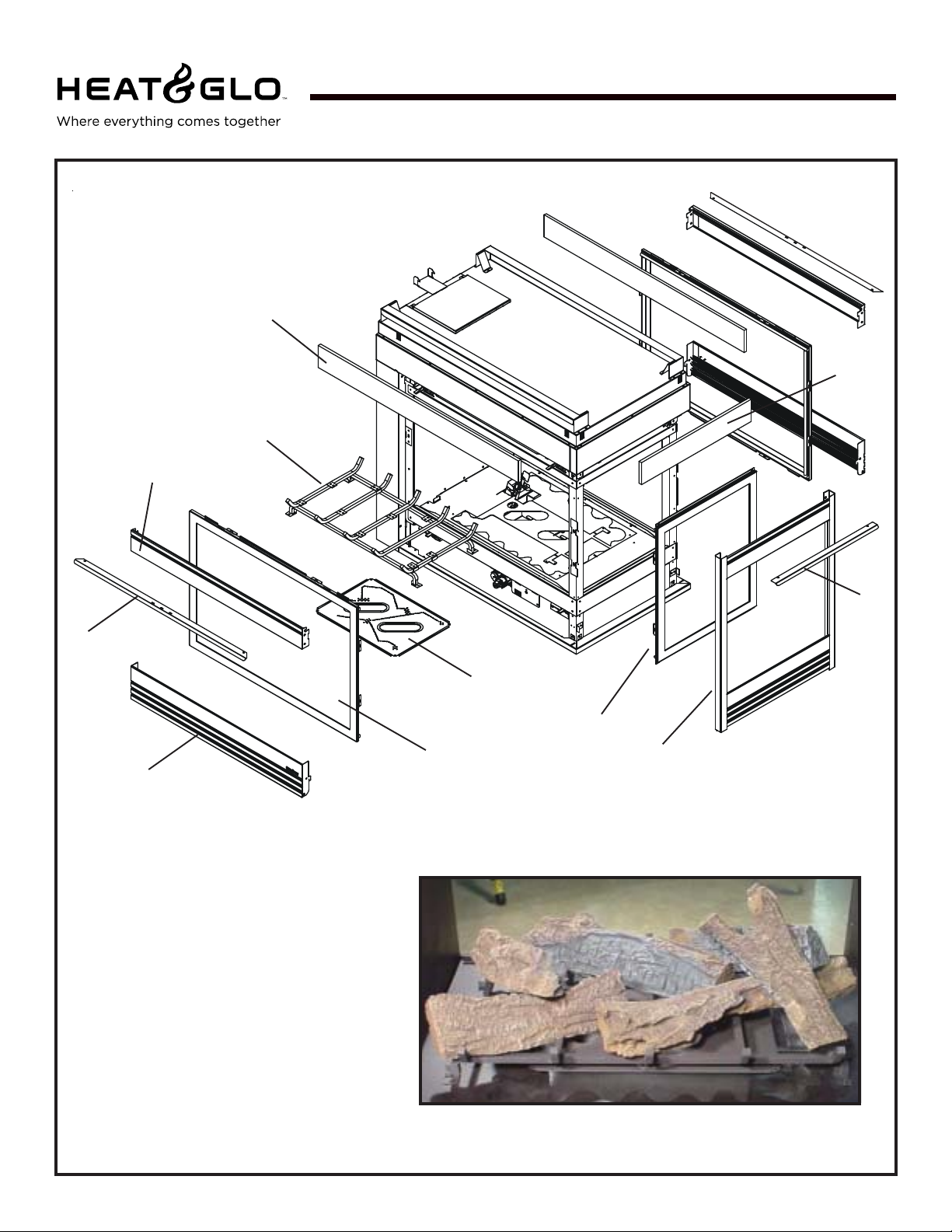
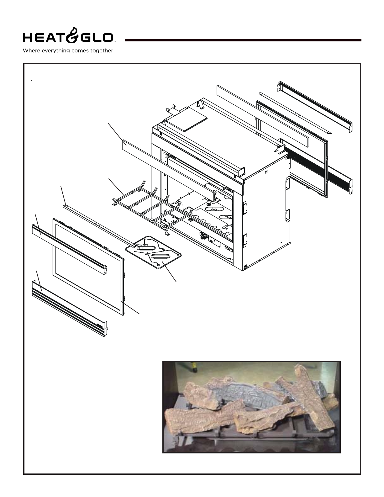
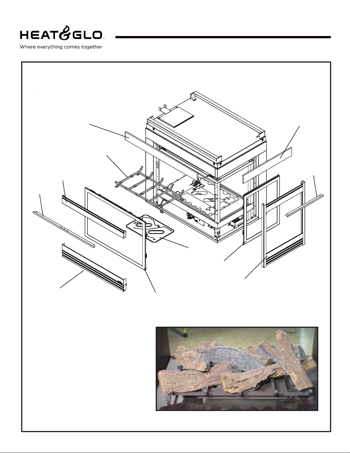
Service Parts List
Pier-HVB-IPI
!
(NG, LP) Exploded Parts Diagram
(GN, PL) Vue éclatée des pièces
9
4
7
Beginning Manufacturing Date: 6-03
Ending Manufacturing Date: ______
10
11
12
3
1
2
8
6
5 Log Assembly
Part number list on following page.
*
La liste des numéros de pièce se trouve à la page suivante.
*
4
Page 5
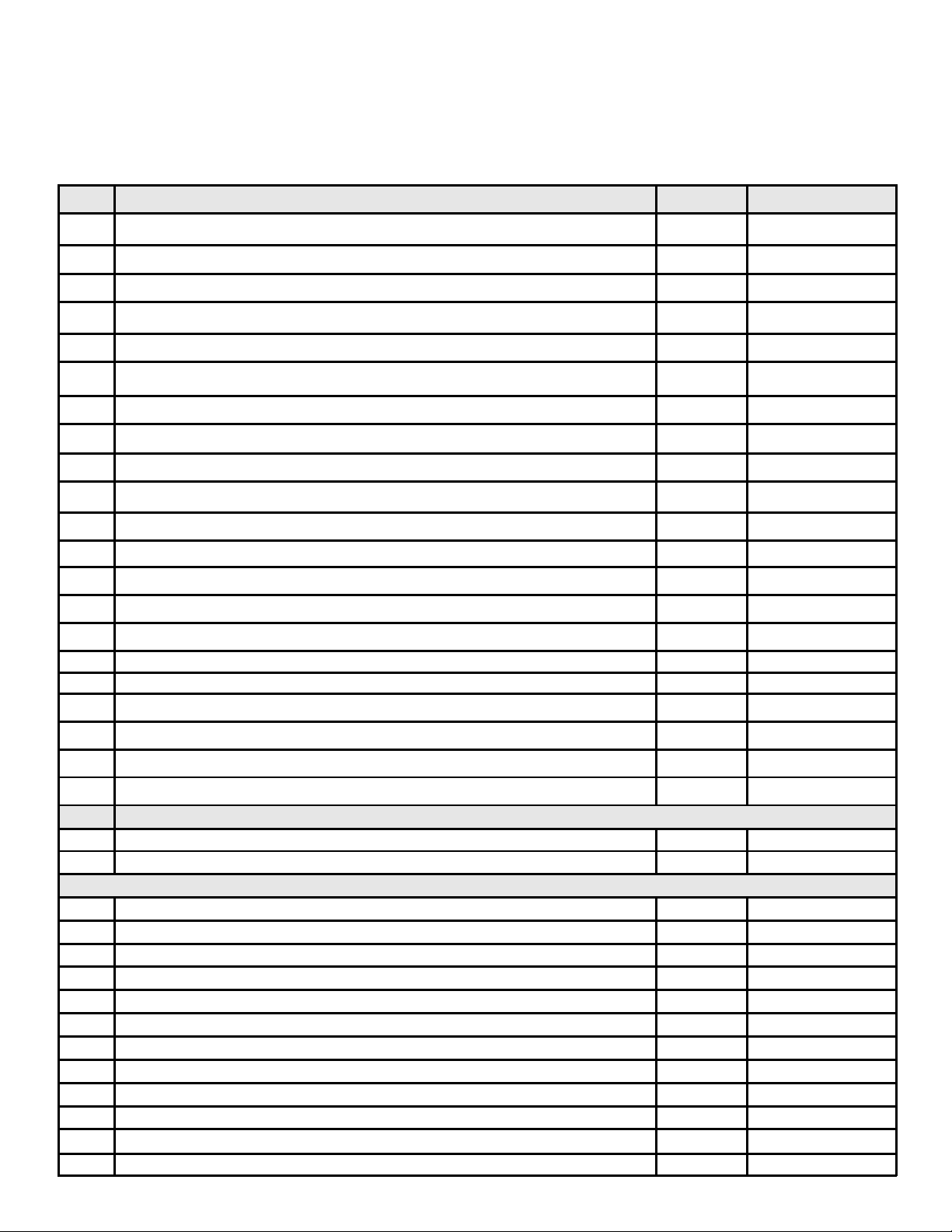
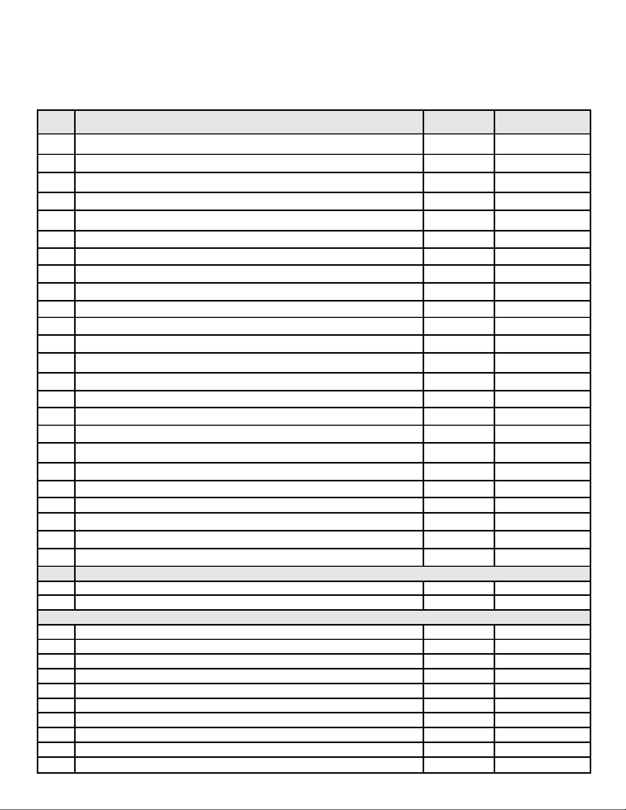
(NG, LP) Exploded Parts Diagram / Vue éclatée des pièces
PIER-HVB-IPI
IMPORT ANT: THIS IS DA TED INFORMA TION. The most current information is located on your dealers VIP site. When ordering,
supply serial and model numbers to ensure correct service parts. / IMPORT ANT : L'information fournie dans cette brochure n'est
valide que pendant une courte période. Les sites VIP des distributeurs disposent des renseignements les plus récents. Lors
d'une commande, veuillez fournir les numéros de série et de modèles pour un remplacement adéquat des pièces.
ITE M /
PIÈCE
Burner Orifice NG (#33C) / Orifice de brûleur GN (#33C) 582-833
Burner Orifice LP (#50C) / Orifice de brûleur PL (#50C) 582-850
1End Glass Assembly GLA-MS
2 Glass Door Assembly / Porte en verre GLA-6TROC
3 Burner Assembly / Brûleur 2039-006
4 Log Grate / Grille de Bûche 2039-012
5 Log Set Assembly (Sold as set only) / Jeu de bûches (Vendu comme mettre seulement) LOGS-MSB
6 Louvers with Mesh - End Panel / Louvers avec la Maille - le Panneau de Fin MS-Louvers-EP
7 Louver, Top / Louvre, supérieure 2040-005
Lava Rock Bag / Le Sac de Rocher de lave 2005-790
Flue Restrictor / Restricteur de conduite de cheminée 385-128
Ember Mesh Assembly / Assemblée de Maille de Charbon ardent 2006-008
Junction Box / Boîtier de raccordement 4021-013
Mesh Assembly / Écran 2005-033A
Bracket, Junction Box / Parenthèse, Boîte de Jonction 2005-173
COMMON PART / PIÉCES COMMUNES
SERIAL #
/ N° DE SÉRI E
PART NUMBER
/ N° DE PIÈC E
8 Louver, Bottom / Louvre, infé rieure 20 4 0-004
9 Insulation Board, Side / Le Conseil d'isolation, le Côté 2006-136
10 Insulation Board, End / Le Conseil d'isolation, la Fin 2006-137
Mineral Wool / Laine minérale 050-721
Fiberglass R ope / Corde de fibre de verre 060-455
Batter y Pack / Paquet de Batterie(Pile) 593-594A
3V Plug 593-593A
11 Hood, black / Le Capuchon, noire SRV2005-190
!
12 Hood End, black / La Fin de Capuchon, noire SRV2006-194
!
IPI IGN ITION ONLY / ALLU M AGE IP I SEULEM ENT
Conversion Kit NG / Modu le de conversion GN NGK-MS
Conversion Kit LP / Module de conversion PL LPK-MS
ACCESSORIES / ACCESSOIRES
Fan Kit / Module de ventilateur GFK-160A
Remote Control Kit / Commande à distance RC-SMART-HNG
Remote Control Kit / Commande à distance SMART-STAT-HNG
Remote Contro l - Multi-functional / Télécommande - Multi-fonct ionnel RCT-ML T-HNG
Wall Switch, Mul t i-fun ctional / Commutateur Mural, Multi-fonctionnel WSK-MLT
Plug Adapator Kit (for W SK-M LT / Branchez(Bouchez) Kit Adapator (pour WSK-MLT) PLUG-ADP
Electric Ember Kit / Kit de Charbon ardent Électrique EmberKit-MS
Logs - Burner - Grate U grade Kit / Rondins - Brûleur - Râpe Kit Ugrade LOGS-UPGRADE
Si de Refra c to ry (Op ti o na l) / C ô té Réfrac ta ire (F a c ultatif) SRV 2005 - 7 3 0
Outside Air Kit / La Trousse d'Air d'extérieur AK-TV
5
Page 6
Service Parts
ST-HVB-IPI
!
(NG , LP) Exploded Parts Diagram
(GN, PL) Vue éclatée des pièces
7
8
5
3
Beginning Manufacturing Date: 6-03
Ending Manufacturing Date: ______
6
Part number list on following page.
*
La liste des numéros de pièce se trouve
*
à la page suivante.
2
1
4 Log Assembly
6
Page 7
(NG, LP) Exploded Parts Diagram / Vue éclatée des pièces
ST-HVB-IPI
IMPORT ANT: THIS IS DA TED INFORMA TION. The most current information is located on your dealers VIP site. When ordering,
supply serial and model numbers to ensure correct service parts. / IMPORT ANT : L'information fournie dans cette brochure n'est
valide que pendant une courte période. Les sites VIP des distributeurs disposent des renseignements les plus récents. Lors
d'une commande, veuillez fournir les numéros de série et de modèles pour un remplacement adéquat des pièces.
ITE M /
PIÈCE
COMMON PART / PIÉCES COMMUNES
SERIAL #
/ N° DE SÉRIE
PART NUMBER
/ N° DE PIÈCE
Burner Ori fice NG (#32C) / Orifice de brûleur GN (#32C) 582-832
Burner Orifice LP (#50C) / Orifice de brûleur PL (#50C) 582-850
1 Glass Door Assembly / Porte en verre GLA-6TROC
2 Burner Assembly / Brûleur 2039-006
3 Log Grate / Grille de Bûche 2039-012
Log Set Assembly (Sold as set only) / Jeu de bûc hes (V endu comme m ettre
4
seul em ent)
LOGS-MSB
5 Louver, Top / Louvre, supérieure 2040-005
6 Louver, Bottom / Louvre, inférieure 2040-004
7 Non-combustible Board / Conseil incombustible 2005-172
Lava Rock Bag / Le Sac de Rocher de lave 2005-790
Flue Restrictor / Restricteur de conduite de cheminée 385-128
Ember Mesh Assembly / Assemblée de Maille de Charbon ardent 2005-008
Junction Box / Boîtier de raccordement 4021-013
Mesh A ssembly / Éc ran 2005-033A
Bracket, Jun ction Box / Parenthèse, Boîte de Jonction 2005-173
3V Plug 593-593A
Battery Pack / Paquet de Batterie(Pile) 593-594A
Mineral Wool / Laine minérale 050-721
Fiberglass R ope / Corde de f ibre de verre 060-455
Glass Latch / Verrou De verr e 386-122A
!
8 Hood, black / Le Capuchon, noire SRV2005-190
IPI IGNITION ONLY / ALLUMAGE IPI S EULEMEN T
Conversion Kit NG / M odule de conver s ion GN NGK-MS
Conversion Kit LP / M odule de conv er sion PL LPK-MS
ACCESSORIES / ACCESSOIRES
Hood, Black, Larger, Optional / Le capuchon, Noir, plus Grand, Facultatif SRV60-143-bk
Fan Kit / Module de ventilateur GFK-160A
Remote Control K it / Commande à d istance RC-SMART-HNG
Remote Control Kit / Commande à distance SMART-STAT-HNG
Remo te Contr ol - Multi- funct iona l / T élécommande - Multi -fonct ionne l RCT-MLT-HN G
Wal l Sw it ch, M ulti-f unctional / Comm ut ateur Mural, Multi- fonctionnel WSK-M LT
Plug Adapat or Kit ( for WSK-M LT / Br a nchez(Bou c hez) Kit Adapa tor ( p our WSK- M LT) PLUG-ADP
Electric Ember Kit / Kit de Charbon ardent Électrique EmberKit-MS
Log s - B urner - Grate Ugrade Kit / Rondi ns - Brûleur - Râpe K it Ugrade LOGS-UPGRADE
Side Refrac to ry (Opti onal) / Côté Réfrac taire (Facultatif) SRV2 005-73 0
Se e through Refractory Ki t / Voir par Kit Réfractaire BRICK -ST-HV
Outside Air Kit / La Trousse d'Air d'extérieur AK-TV
7
Page 8
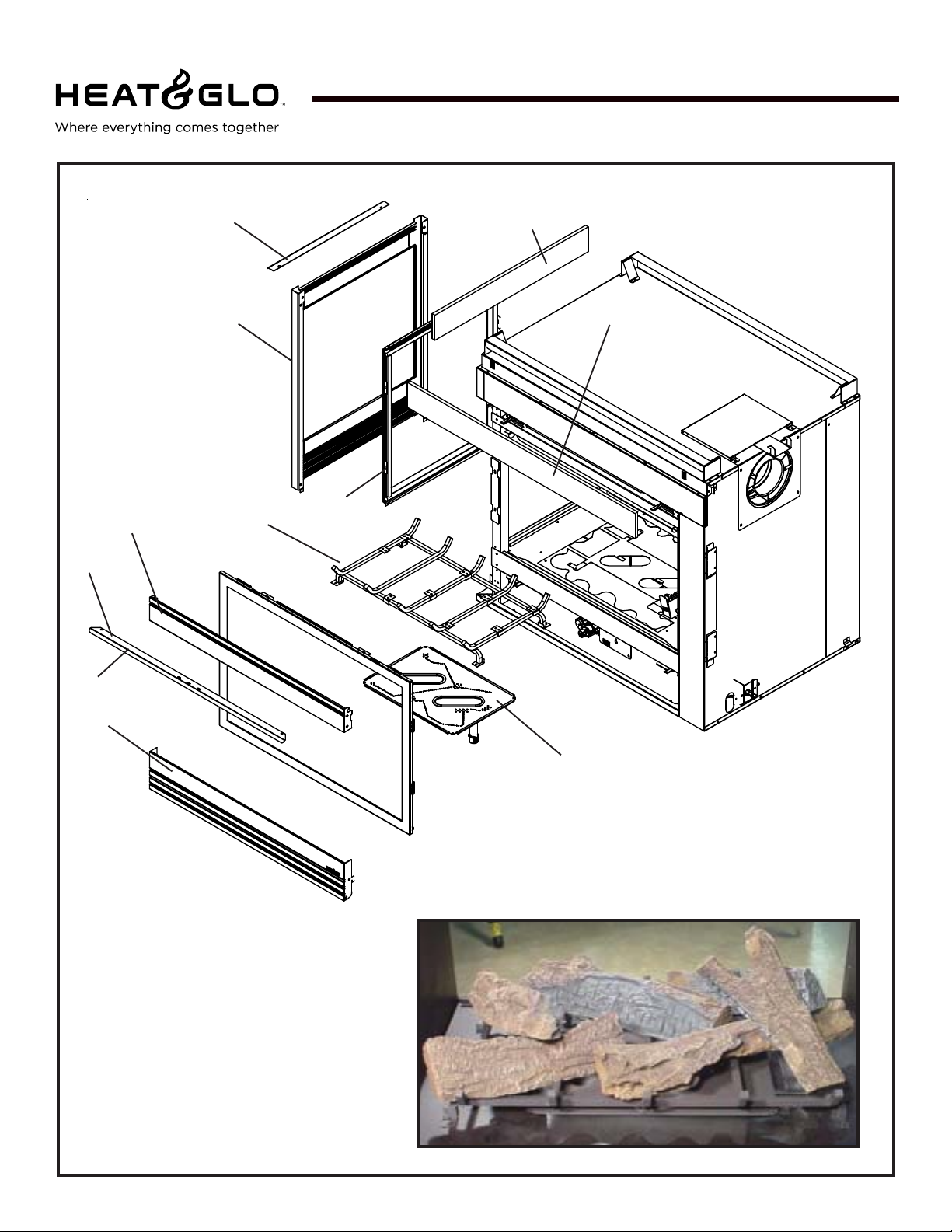
Service Parts
LCOR-HVB-IPI
!
(NG , LP) Exploded Parts Diagram
(GN, PL) Vue éclatée des pièces
12
6
1
2
7
4
10
9
Beginning Manufacturing Date: 6-03
Ending Manufacturing Date: ______
11
8
Part number list on following page.
*
La liste des numéros de pièce se trouve
*
à la page suivante.
3
5 Log Assembly
8
Page 9
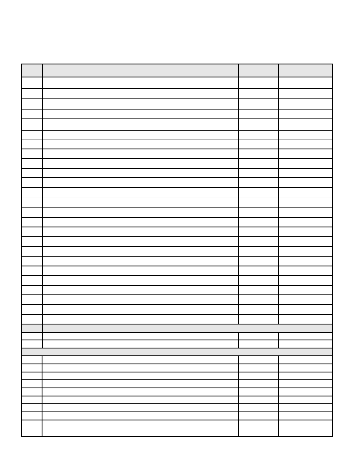
(NG , LP) Exploded Part s Diagram / Vue éclatée des pièces
LCOR-HVB-IPI
IMPORT ANT: THIS IS DA TED INFORMA TION. The most current information is located on your dealers VIP site. When ordering,
supply serial and model numbers to ensure correct service parts. / IMPORT ANT : L'information fournie dans cette brochure n'est
valide que pendant une courte période. Les sites VIP des distributeurs disposent des renseignements les plus récents. Lors
d'une commande, veuillez fournir les numéros de série et de modèles pour un remplacement adéquat des pièces.
ITE M /
PIÈCE
Burner Orifice NG (#32C) / Orifice de brûleur GN (#32C) 582-832
Burner Orifice LP (#50C) / Orifice de brûleur PL (#50C) 582-850
1 End Glass A s semb ly GLA-MS
2 Glass Door Assembly / Porte en verre GLA-6TROC
3 Burner Assembly / Brûleur 2039-006
4 Log Grate / Grille de Bûche 2039-012
5 Log Set Assembly (Sold as set only) / Jeu de bûches (Vendu comme mettre seulement) LOGS-MSB
6 Louvers with Mesh - End Panel / Louvers avec la Maille - le Panneau de Fin MS-Louvers-EP
7 Louver, Top / Louvre, supérieure 2040-005
8 Louv er, Bo ttom / Louv re, inférieure 2040-004
9 Insulation Board, Si de / Le C o nseil d'isolation, le Côté 2006-136
10 Insulation Board, End / Le Conseil d'isolation, la Fin 2008-114
Lava Rock Bag / Le S ac de Rocher de lave 2005-790
Flue Restrictor / Restricteur de conduite de cheminée 385-128
Ember Mesh Assembly / Assemblée de Maille de Charbon ardent 2006-008
Junction Box / Boîtier de raccordement 4021-013
Mesh Assembly / Écran 2005-033A
Bracket, Junction Box / Parenthèse, Boîte de Jonction 2005-173
Mineral Wool / Laine minérale 050-721
Fiberglass Rope / Corde de fibre de verre 060-455
Glass Latch / Verrou De verre 386-122A
3V Plug 593-593A
Battery Pack / Paquet de Batterie(Pile) 593-594A
!
!
11 Hood, black / Le Capuchon, noire SRV2005-190
12 Hood End, black / La Fin de Capuchon, noire SRV2006-194
IPI IGNITION ONLY / ALL UMAGE IP I SEULEM ENT
Conversion Kit NG / Module de conversion GN NGK-MS
Conversion Kit LP / Module de conversion PL LPK-MS
ACCESSORIES / ACCESSOIRES
Fan Kit / Module de ventilateur GFK-160A
Remote C o ntrol Kit / Comma nde à di s tance RC-SMA RT-HNG
Remote Control Kit / Command e à distance SMART-STAT-HNG
Remote Contr ol - Multi-function al / Télécommande - Multi-fonctionn el RCT-MLT-HNG
Wall Switch, Multi-functional / Commutateur Mural, Multi-fonctionnel WSK-MLT
Plug Adapator Kit (f or WSK-MLT / Branchez(Bouchez) Kit Adapator (pour W SK-MLT) PLUG-ADP
Electric Ember Kit / Kit de Charbon ardent Électrique EmberKit-MS
Logs - Burner - Grat e Ugrade Kit / R ondins - Brûleur - Râpe Kit Ugrade LOGS-UPGRADE
Side Re fra cto r y (Opti o nal) / Côté Ré fra cta ire (F a c ultati f)
Corner Refractory Kit / Coincez(Verrouillez) Kit Réfractaire BRICK-COR-HV
COMMON PART / PIÉCES COMMUNES
SERIAL #
/ N° DE SÉRIE
PART NUMBER
/ N° DE PIÈCE
SRV2005-730
9
Page 10
Service Parts
RCOR-HVB-IPI
!
11
(NG , LP) Exploded Parts Diagram
(GN, PL) Vue éclatée des pièces
9
4
7
Beginning Manufacturing Date: 6-03
Ending Manufacturing Date: ______
10
12
8
Part number list on following page.
*
La liste des numéros de pièce se trouve
*
à la page suivante.
3
1
6
2
5 Log Assembly
10
Page 11
(NG , LP) Exploded Part s Diagram / Vue éclatée des pièces
RCOR-HVB-IPI
IMPORT ANT: THIS IS DA TED INFORMA TION. The most current information is located on your dealers VIP site. When ordering,
supply serial and model numbers to ensure correct service parts. / IMPORT ANT : L'information fournie dans cette brochure n'est
valide que pendant une courte période. Les sites VIP des distributeurs disposent des renseignements les plus récents. Lors
d'une commande, veuillez fournir les numéros de série et de modèles pour un remplacement adéquat des pièces.
ITE M /
PIÈCE
Burner Orifice NG (#32C) / Orifice de brûleur GN (#32C) 582-832
Burner Orifice LP (#50C) / Orifice de brûleur PL (#50C) 582-850
1 End Glass Assembly GLA-MS
2 Glass Door Assembly / Porte en verre GLA-6TROC
3 Burner Assembly / Brûleur 2039-006
4 Log Grate / Grille de Bûche 2039-012
5 Log Set Assembly ( Sold as set only) / Jeu de bûches (Vendu comme mettre seulement) LOGS-MSB
6 Louvers with Mesh - End Panel / Louvers avec la Maille - le Panneau de Fin MS-Louvers-EP
7 Louver, Top / Louvre, supérieure 2040-005
8 Louver, Bottom / Louvre, inférieure 2040-004
9 Insulation Board, Side / Le Conseil d'isolation, le Côté 2006-136
10 Insulation Bo ard, End / Le Conseil d'isolation, la Fin 2 008-114
Lava Rock Bag / Le Sac de Rocher de lave 2005-790
Flue Restrictor / Restricteur de conduite de cheminée 385-128
Ember Mesh Assembly / Assemblée de Maille de Charbon ardent 2006-008
Junction Box / Boîtier de raccordement 40 21-013
COMMON PART / PIÉCES COMMUNES
SERIAL #
/ N° DE SÉRIE
PART NUMBER
/ N° DE PIÈCE
Bracket, Junction Box / Parenthèse, Boîte de Jonction 2005-173
Mineral Wool / Laine minérale 050-721
Fiberglass Rope / Corde de fibre de verre 060-455
Glass Latch / Verrou De verre 386-122A
3V Plug 593-593A
Battery Pack / Paqu et de Batterie(Pile) 593-594A
11
!
!
ACCESSORIES / ACCESSOIRES
Hood, black / Le Capuchon, noire SRV2005-190
12 Hood End, black / La Fin de Capuchon, noire SRV2006-194
IPI IGNITION ONLY / ALLUMAGE IPI SEULEMENT
Conversion Kit NG / Module de conversion GN NGK-MS
Conversion Kit LP / Module de conversion PL LPK-MS
Fan Kit / Module de ventilateur GFK-160A
Remote Control Kit / Commande à distance RC-SMART-HNG
Remote Control Kit / Commande à distance SMART-STAT-HNG
Remote Control - Mu lti-f unc tional / Télécommande - Mult i- fonctionnel RCT-MLT-HNG
Wall Switch, Multi-functional / Commutateur Mural, Multi-fon ctionnel WSK-MLT
Plug Adapator Kit (for WSK-M LT / Branchez(Bouchez) Kit Adapator ( pour WSK-MLT) PLUG-ADP
Electric Ember Kit / Kit de Charbon ardent Électrique EmberKit-MS
Logs - Burner - Grate U grade Kit / Rondins - Brû leur - Râpe Kit Ugrade LOGS-UPGRADE
Side Refractory (Optional) / Côté Réfractaire (Facultatif) SRV2005-730
Corner Refractory Kit / Coincez(Verrouillez) Kit Réfractaire BRICK-COR-HV
11
Page 12
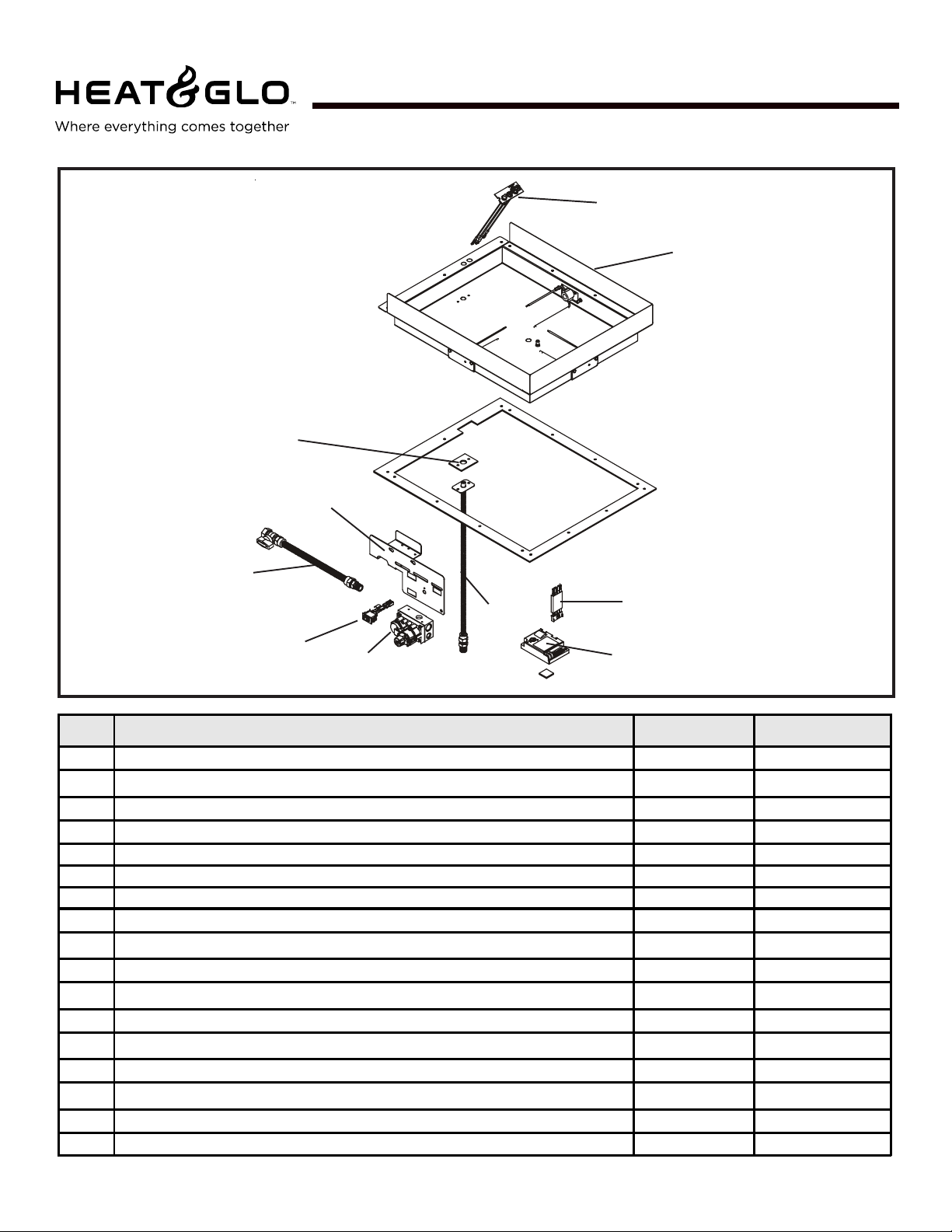
PIER-HVB-IPI, ST-HVB-IPI
!
10
Service Parts
(NG , LP) Exploded Parts Diagram
(GN, PL) Vue éclatée des pièces
9
L&RCOR-HVB-IPI
Beginning Manufacturing Date: 6-03
Ending Manufacturing Date: ______
8
7
1
4
2
3
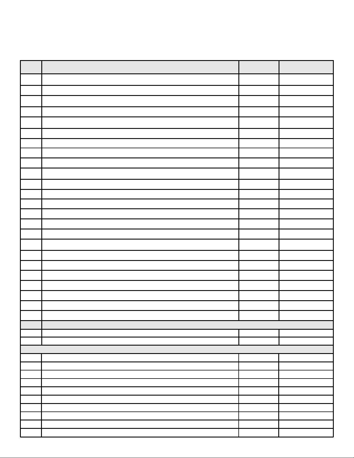
ITEM DESCRIPTION SERIAL # PART NUMBER
1 Flex Ball Valve Assembly / Fléchir l'Assemblée de Soupape de Balle 302-320A
2 ON / OFF Wire Assem b l y / Assemblée "MARCHE/ARRÊT " d e Fil 060-521A
3Valve NG / Valve GN 750-500
3 Valve LP / Valve PL 750-501
4 Flexible Gas Connector / Tuyau à gaz flexible 2005-009
5 Module / Module 593-592
6 Wire Assembly / Module de fil 593-590A
7 Ember Box Assembly / Assemblée de Box 'Ampoule) de Charbon ardent 2005-014
8
Pilot Assembly NG / Module de veilleuse NG
8 Pilot Assembly LP / Module de veilleuse PL 385-511A
9 Valve Bracket / Parenthèse de Valve 2005-120
10 Gasket Orifice / Orifice de Joint 2005-166
Pilot Support Arm / Piloter le Bras de Soutien 385-120
Ground Strap / Courroie de Raison(Terre) 385-512
Pilot Tube / Tu be de veilleuse 446-301
Orifice Spud NG / Pioche d'Orifice GN 446-505
Orifice Spud LP / Pioche d'Orifice PL 446-517
6
5
385-510A
"
"
NOTE: Replacement bulbs to be supplied by homeowner. Recommended replacements: Sylvania Mini Candelabra 75 watts.
12
Page 13

1
Approvals and
Codes
Appliance Certification
The Heat & Glo fireplace models discussed in this Installers
Guide have been tested to certification standards and listed
by the applicable laboratories.
Certification
MODELS: PIER-HVB-IPI, S T- HV B-IPI,
LCOR-HVB-IPI, RCOR-HVB-IPI
LABORATORY: Underwriters Laboratories
TYPE: V ented Gas Fireplace Heater
STANDARD: ANSI Z21.88•CGA2.22•UL307B
Installation Codes
The fireplace installation must conform to local codes. Before
installing the fireplace, consult the local building code
agency to ensure that you are in compliance with all
applicable codes, including permits and inspections.
In the absence of local codes, the fireplace installation must
conform to the National Fuel Gas Code ANSI Z223.1 (in the
United States) or the CAN/CGA-B149 Installation Codes
(in Canada). The appliance must be electrically grounded
in accordance with local codes or, in the absence of local
codes with the National Electric Code ANSI/NFPA No. 70
(in the United St ates), or to the CSA C22.1 Canadian Electric
Code (in Canada).
High Altitude Installations
U.L. Listed gas appliances are tested and approved without requiring changes for elevations from 0 to 2,000 feet in
the U. S. A. and in Canada.
When installing this appliance at an elevation above 2,000
feet, it may be necessary to decrease the input rating by
changing the existing burner orifice to a smaller size. Input
rate should be reduced by 4% for each 1000 feet above a
2000 foot elevation in the U.S.A. or 10% for elevations
between 2000 and 4500 feet in Canada. If the heating value
of the gas has been reduced, these rules do not apply . To
identify the proper orifice size, check with the local gas
utility.
If installing this appliance at an elevation above 4,500 feet
(in Canada), check with local authorities.
These models may be installed in a bedroom or bed-sitting
room in the U.S.A. and Canada.
Heat & Glo Quality
Systems registered
by SGS ICS
13
Page 14

2
Getting Started
Introducing the Heat & Glo Gas Fireplaces
Heat & Glo direct vent gas fireplaces are designed to operate with all combustion air siphoned from outside of the
building and all exhaust gases expelled to the outside.
The information contained in this Installers Guide, unless
noted otherwise, applies to all models and gas control
systems. Gas fireplace diagrams, including the dimensions,
are shown in this section.
Pre-install Preparation
This gas fireplace and its components are tested and safe
when installed in accordance with this Installers Guide.
Report to your dealer any parts damaged in shipment,
particularly the condition of the glass. Do not install any
unit with damaged, incomplete, or substitute parts.
The vent system components are shipped in separate packages. The gas logs are packaged separately and must be
field installed.
Read all of the instructions before starting the installation. Follow these instructions carefully during the
installation to ensure maximum safety and benefit.
Failure to follow these instructions will void the owner’s warranty and may present a fire hazard.
The Heat & Glo Warranty will be voided by , and Heat & Glo
disclaims any responsibility for, the following actions:
• Installation of any damaged fireplace or vent system
component.
• Modification of the fireplace or direct vent system.
• Installation other than as instructed by Heat & Glo.
• Improper positioning of the gas logs or the glass door.
• Installation and/or use of any component part not manufactured and approved by Heat & Glo, not withstanding
any independent testing laboratory or other party approval
of such component part or accessory .
ANY SUCH ACTION MAY POSSIBLY CAUSE A FIRE
HAZARD.
When planning a fireplace installation, it’s necessary
to determine:
• Where the unit is to be installed.
• The vent system configuration to be used.
• Gas supply piping.
• Electrical wiring.
• Framing and finishing details.
• Whether optional accessories—devices such as a fan,
wall switch, or remote control—are desired.
If the fireplace is to be installed on carpeting or tile,
or on any combustible material other than wood
flooring, the fireplace should be installed on a metal
or wood panel that extends the full width and depth
of the fireplace.
14
Page 15

12
(306mm)
Ø8
(204mm)
1/2
(13mm)
(2)
5-1/4
(133mm)
34-3/4
(882mm)
4-1/16
(102mm)
4-1/2
(114mm)
12
(305mm)
TOP VENT
COLLARS
Ø8
(204mm)
ELECTRICAL
ACCESS
GAS LINE
ACCESS
2-5/16
(58mm)
4-3/4
(121mm)
42
(1067mm)
TOP STANDOFFS
42-5/8
(1082mm)
32-5/16
(820mm)
37-7/16
(950mm)
21
(533mm)
8-1/2
(216mm)
(610mm)
REAR VENT
COLLARS
17-15/16
(455mm)
24
21
(533mm)
GAS CONTRO LS
& LABELS
Figure 1. Diagram of the PIER-HVB-IPI
15
SIDE GLASS
DOOR
ELECTRICAL
ACCESS
GAS LINE
ACCESS
Page 16

12
(306mm)
Ø8
(204mm)
5-14
(133mm)
1/2
(13mm)
(4)
34-3/4
(882mm)
4-1/16
(102mm)
4-1/2
(114mm)
(305mm)
TOP VENT
COLLARS
12
ELECTRICAL
ACCESS
Ø8
(204mm)
GAS LIN E
ACCESS
2-5/16
(58mm)
4-3/4
(121mm)
42
(1067mm)
TOP STANDOFFS
46-5/8
(1183mm)
32-5/16
(820mm)
36-3/16
(919mm)
21
(533mm)
8-1/2
(216mm)
24
(610mm)
REAR VENT
COLLARS
4-1/2
(114mm)
2-9/16
(64mm)
GAS CONTROLS
& LABELS
Figure 2. Diagram of the ST-HVB-IPI
16
SIDE GLASS
DOOR
ELECTRICAL
ACCESS
GAS LINE
ACCESS
Page 17

5-1/4
(133mm)
(204mm)
12
(305mm)
Ø8
1/2
(13mm)
(4)
34-3/4
(882mm)
Ø8
(204mm)
TOP VENT
COLLARS
10
(254mm)
(184mm)
12
(305mm)
ELECTRICAL
ACCESS
GAS LINE
ACCESS
2-9/16
(64mm)
2-5/16
(58mm)
4-3/4
(121mm)
TOP STANDOFFS
42-5/8
(1082mm
(533mm)
32-5/16
(820m)
37-7/16
(950mm)
17-15/16
(455mm)
42
21
(1066mm
8-1/2
(216mm)
24-1/8
(612mm)
29-1/4
(743mm)7-1/4
REAR VENT
COLLARS
21
(533mm)
SIDE GLASS
DOOR
END GLASS
GAS CONTROLS
& LABELS
DOOR
Figure 3. Diagram of the LCOR-HVB-IPI and RCOR-HVB-IPI
17
ELECTRICAL
ACCESS
GAS LINE
ACCESS
Page 18

3
Installing the Fireplace
Step 1. Locating the Fireplace
The diagram below shows space and clearance requirements for locating a fireplace within a room.
36"
36"
GLASS
36"
GLASS
GLASS
RCOR-HVB-IPI
TOP VIEW
36"
36"
GLASS
LCOR-HVB-IPI
TOP VIEW
GLASS
GLASS
36"
ST-HVB-IPI
TOP VIEW
36"
GLASS
PIER-HVB-IPI
TOP VIEW
GLASS
GLASS
Minimum Clearances
from the Fireplace to Combustible Materials
Inches mm
Glass Sides or Ends.......... 36 .................... 914
Floor ................................... 0 ....................... 0
Rear Vent...........................1/2 ..................... 13
Metal Sides or Ends ..........1/2 ..................... 13
Top................................... 2 1/2 ................... 6 4
Ceiling* .............................. 31 .................... 787
* The clearance to the ceiling is measured from the top of
the unit, excluding the standoffs (see Figures 37 & 38).
The distance from the unit to combustible construction is to
be measured from the unit outer wrap surface to the combustible construction, NOT from the screw heads that secure the unit together.
Minimum Clearances
from the Vent Pipe to Combustible Materials
Inches mm
Vertical Sections. ............. 1 ................ 25
Horizontal Sections
Top..................................... 3 ................ 75
Bottom ............................... 1 ................ 25
Sides ................................. 1 ................ 25
At Wall Firestops
Top.................................. 2 1/2 ............63.7
Bottom ..............................1/2............... 13
Sides ................................. 1 ................ 25
Figure 4. Fireplace Dimensions and Locations
Clearance Requirements
The top, back, and sides of the fireplace are defined by
stand-offs. The minimum clearance to a perpendicular wall
extending past the face of the fireplace is one inch (25 mm).
The metal ends of the fireplace may NOT be recessed into
combustible construction.
For minimum clearances, see the direct vent termination
clearance diagrams on pages 30 and 31 in this manual.
Step 2. Framing the Fireplace
Fireplace framing can be built before or after the fireplace is
set in place. Framing should be positioned to accommodate wall coverings and fireplace facing material. The diagram below shows framing reference dimensions.
CAUTION: MEASURE FIREPLACE DIMENSIONS AND
VERIFY FRAMING METHODS AND WALL COVERING
DET AILS BEFORE FRAMING .
WARNING: FRAMING DIMENSIONS ASSUME
!
USE OF 1/2 INCH THICK WALL COVERING
MA TERIALS ON EXTERIOR OF FRAMING ONL Y AN D
NO SHEETROCK ON INTERIOR OF FRAMING .
18
Page 19

Shows center of 10” x 12” vent framing holes for top and rear venting. The center
of the hole is one inch (25.4mm) above the center of the horizontal vent pipe.
E
D
Framing should be
constructed of 2 X 4
lumber or heavier .
ST-HV-IPI L & R-COR-HV-IPI
B
C
A
A
PIER-HV-IPI
B
B
C
A
C
Model A B C D E
PIER-HVB-IPI 42-1/8 42-1/2 23 35-3/4 48
ST-HVB-IPI 47-5/8 42-1/2 23 35-3/4 48
L&RCOR-HVB-IPI 42-1/8 42-1/2 28-3/4 35-3/4 48
Figure 5. Framing Dimensions
NOTE: DIMENSIONS SHOWN IN INCHES
19
Page 20

12-3/16
MAX.
DVP12
12
2
MIN.
6
4
DVP4
DVP6
14-1/4
24
9-7/8
DVP12A
10-1/4
DVP45
45.0
36
48
O
DVP24
DVP36
11-1/4
7-1/4
1-1/4 TYP
DVP48
1/2 TYP
NOTE: PIPES OVERLAP 1-1/4 INCHES
AT EACH JOINT.
12-9/16
V
D
P
0
9
8-9/16
S
T
Figure 6. DVP-Series Direct Vent Component Specifications (5-inch inner pipe / 8-inch outer pipe)
20
Page 21

Step 3. Installing the Vent System
A. Vent System Approvals
These models are approved to use DVP series direct vent
pipe components and terminations (see Figures 6 and 7).
Approved vent system components are labeled for identification. This pipe is tested and listed as an approved component of the fireplace. The pipe is tested to be run inside
an enclosed wall. There is no requirement for inspection
openings at each joint within the wall. There is no required
pitch for horizontal vent runs. NO OTHER VENTING SYS-
TEMS OR COMPONENTS MA Y BE USED.
Detailed installation instructions are included with each vent
termination kit and should be used in conjunction with this
Installers Guide.
The flame and ember appearance may vary based on the
type of fuel burned and the venting configuration used.
Identifying Vent Component s
The vent systems installed on this gas fireplace may include one, two, or three 90°
elbow assemblies. The relationships of vertical rise to horizontal run in vent configurations using 90° elbows MUST BE strictly adhered to. The
rise to run relationships are shown in the venting drawings
and tables. Refer to the diagrams on the next several pages.
NOTE: Two 45° elbows may be used in place of one
90° elbow. Rise to run ratios in the vent system must
be followed if 45° elbows are used.
This model has a 45
0
elbow built into it. It may be positioned to vent either horizontal or vertical. Depending on the
installation, decide which direction the elbow should be facing. Remove the 8 screws from the corner cover plate. Position the 450 elbow as desired and replace the corner cover plate with the 8 screws.
T erminations Kits
VERTICAL
TERMINATION
HORIZONTAL
TERMINATION
STORM COLLAR
ROOF FLASHING
WALL FIRESTOP
PIPE LENGTH
90 DEGREE
ELBOW
CEILING
FIRESTOP
DVP-TVPVK-80
DVP-TRAP
SERIES
DVP-TVHW
DVP-TB1
(Required to have a minimum of 3
feet of vertical in the vent system)
Figure 7. Vent System Component s and Termination Kits
21
Page 22

STRAIGHT UP
VERTICAL VENTING
V (FT.)
50' MAX. (15.2 M)
CAP
V
NOTE: On vertical venting
configurations you may
want to install the flue restrictor (385-128). See flue
restrictor installation instructions.
Figure 8
Flue Restrictor Instructions
1. Locate the Flue Restrictor which is in the manual
bag.
BREAK
HERE
Figure 10. Flue Restrictor
3. Match the amount of
vertical in the system
with the chart to find the
appropriate position to
set the Flue Restrictor.
- CHART -
Vertical Settings
4' 1-1
8' 1-2
15' 2-2
20' 2-3
25' 3-3
30' 4-3
35' 4-4
40' 4-4
50' 4-5
4.Center the Flue Restrictor on vent and secure in
place using two self-tapping screws (see Figure 11).
1 2 3 4 5
FLUE
RESTRICTOR
Figure 9
2. Break the Flue Restrictor into two pieces. Do this
by bending the part back and forth until it breaks
(see Figure 10).
SETTINGS
1 2 3 4 5
Figure 11
STRAIGHT OUT
HORIZONT AL VENTING
H
Max. Run
24" (610 mm)
H
Figure 12.
22
Page 23

V
NATURAL GAS - VENTING WITH ONE 90° ELBOW
V (FT.) H (FT.)
1' MIN. (305mm) 3' MAX. (914mm)
2' MIN. (610mm) 6' MAX. (1.83m)
3' MIN. (914mm) 9' MAX. (2.7m)
4' MIN. (1.22m) 12' MAX. (3.6m)
5’ MIN. (1.5m) 15’ MAX. (4.5m)
6’ MIN. (1.83m) 18’ MAX. (5.5m)
V + H = 50’ MAX. (15.2m)(11.3m)
PROPANE - VENTING WITH ONE 90° ELBOW
V (FT.) H (FT.)
1' MIN. (305mm) 2' MAX. (610mm)
2' MIN. (610mm) 4' MAX. (1.22m)
3' MIN. (914mm) 6’ MAX. (1.83m)
4' MIN. (1.22m) 8' MAX. (2.4m)
5’ MIN. (1.5m) 10' MAX. (3.0m)
6’ MIN. (1.83m) 12' MAX. (3.6m)
V + H = 50’ MAX. (15.2m)
Figure 13. Venting with One 90° Elbow
V
H
NATURAL GAS
VENTING WITH ONE 90° ELBOW
V (FT.) H (FT.)
900 Elbow on top 2.5’ MAX. (64mm)
1' MIN. (305mm) 3' MAX. (914mm)
2' MIN. (610mm) 6' MAX. (1.83m)
3' MIN. (914mm) 9' MAX. (2.7m)
4' MIN. (1.22m) 12' MAX. (3.6m)
5’ MIN. (1.5m) 15’ MAX. (4.5m)
6’ MIN. (1.83m) 18’ MAX. (5.5m)
V + H = 50’ MAX. (15.2m)
H
PROP ANE
VENTING WITH ONE 90° ELBOW
V (FT.) H (FT.)
900 Elbow on top 2’ MAX. (610mm)
1' MIN. (305mm) 2' MAX. (610mm)
2' MIN. (610mm) 4' MAX. (1.22m)
3' MIN. (914mm) 6’ MAX. (1.83m)
4' MIN. (1.22m) 8' MAX. (2.4m)
5’ MIN. (1.5m) 10' MAX. (3.0m)
6’ MIN. (1.83m) 12' MAX. (3.6m)
V + H = 50’ MAX. (15.2m)
Figure 14. Venting with One 90° Elbow
23
Page 24

V
V
NATURAL GAS
VENTING WITH TWO 90° ELBOWS
V (FT.) H + H
1
(FT.)
900 Elbow on top 2.5’ MAX. (64mm)
1' MIN. (305mm) 3' MAX. (914mm)
2' MIN. (610mm) 6' MAX. (1.83m)
3' MIN. (914mm) 9' MAX. (2.7m)
4' MIN. (1.22m) 12' MAX. (3.6m)
5’ MIN. (1.5m) 15’ MAX. (4.5m)
6’ MIN. (1.83m) 18’ MAX. (5.5m)
V + H + H1 = 50’ MAX. (15.2m)
H + H1 = 18’ MAX. (5.5m)
PROP ANE
VENTING WITH TWO 90° ELBOWS
V (FT.) H + H
1
(FT.)
900 Elbow on top 2’ MAX. (610mm)
1' MIN. (305mm) 2' MAX. (610mm)
2' MIN. (610mm) 4' MAX. (1.22m)
3' MIN. (914mm) 6’ MAX. (1.83m)
4' MIN. (1.22m) 8' MAX. (2.4m)
5’ MIN. (1.5m) 10' MAX. (3.0m)
6’ MIN. (1.83m) 12' MAX. (3.6m)
V + H + H1 = 50’ MAX. (15.2m)
H + H1 = 12’ MAX. (3.6m)
H
1
H
NATURAL GAS
VENTING WITH TWO 90° ELBOWS
V + V
(FT.) H (FT.)
1
900 Elbow on top 2.5’ MAX. (64mm)
1' MIN. (305mm) 3' MAX. (914mm)
2' MIN. (610mm) 6' MAX. (1.83m)
3' MIN. (914mm) 9' MAX. (2.7m)
4' MIN. (1.22m) 12' MAX. (3.6m)
5’ MIN. (1.5m) 15’ MAX. (4.5m)
6’ MIN. (1.83m) 18’ MAX. (5.5m)
V + V1 + H = 50’ MAX. (15.2m)
PROP ANE
VENTING WITH TWO 90° ELBOWS
V + V
(FT.) H (FT.)
1
900 Elbow on top 2’ MAX. (610mm)
1' MIN. (305mm) 2' MAX. (610mm)
2' MIN. (610mm) 4' MAX. (1.22m)
3' MIN. (914mm) 6’ MAX. (1.83m)
4' MIN. (1.22m) 8' MAX. (2.4m)
5’ MIN. (1.5m) 10' MAX. (3.0m)
6’ MIN. (1.83m) 12' MAX. (3.6m)
V + V1 + H = 50’ MAX. (15.2m)
Figure 15. Venting with Two 90° Elbows
V
1
H
24
Page 25

V
NATURAL GAS
VENTING WITH TWO 90° ELBOWS
V (FT.) H + H
1
(FT.)
1' MIN. (305mm) 3' MAX. (914mm)
2' MIN. (610mm) 6' MAX. (1.83m)
3' MIN. (914mm) 9' MAX. (2.7m)
4' MIN. (1.22m) 12' MAX. (3.6m)
5’ MIN. (1.5m) 15’ MAX. (4.5m)
6’ MIN. (1.83m) 18’ MAX. (5.5m)
V + H + H
= 50’ MAX. (15.2m)
1
1
H + H
= 18’ MAX. (5.5m)
H
1
PROP ANE
VENTING WITH TWO 90° ELBOWS
V (FT.) H + H
1
(FT.)
1' MIN. (305mm) 2' MAX. (610mm)
2' MIN. (610mm) 4' MAX. (1.22m)
3' MIN. (914mm) 6’ MAX. (1.83m)
4' MIN. (1.22m) 8' MAX. (2.4m)
5’ MIN. (1.5m) 10' MAX. (3.0m)
6’ MIN. (1.83m) 12' MAX. (3.6m)
1
V + H + H
= 50’ MAX. (15.2m)
H + H1 = 12’ MAX. (3.6m)
Figure 16.
Venting with Two 90° Elbows
V
NATURAL GAS
VENTING WITH TWO 90° ELBOWS
V (FT.) H + H
1
(FT.)
1' MIN. (305mm) 3' MAX. (914mm)
2' MIN. (610mm) 6' MAX. (1.83m)
3' MIN. (914mm) 9' MAX. (2.7m)
4' MIN. (1.22m) 12' MAX. (3.6m)
5’ MIN. (1.5m) 15’ MAX. (4.5m)
6’ MIN. (1.83m) 18’ MAX. (5.5m)
V + H + H1 = 50’ MAX. (15.2m)
H + H1 = 18’ MAX. (5.5m)
H
PROPANE
VENTING WITH TWO 90° ELBOWS
V (FT.) H + H
1
(FT.)
1' MIN. (305mm) 2' MAX. (610mm)
2' MIN. (610mm) 4' MAX. (1.22m)
3' MIN. (914mm) 6’ MAX. (1.83m)
4' MIN. (1.22m) 8' MAX. (2.4m)
5’ MIN. (1.5m) 10' MAX. (3.0m)
6’ MIN. (1.83m) 12' MAX. (3.6m)
V + H + H1 = 50’ MAX. (15.2m)
H + H1 = 12’ MAX. (3.6m)
H
1
H
Figure 17. Venting with Two 90° Elbows
25
Page 26

V
NATURAL GAS
VENTING WITH THREE 90° ELBOWS
1
V + V
(FT.) H + H1 (FT.)
1' MIN. (305mm) 3' MAX. (914mm)
2' MIN. (610mm) 6' MAX. (1.83m)
3' MIN. (914mm) 9' MAX. (2.7m)
4' MIN. (1.22m) 12' MAX. (3.6m)
5’ MIN. (1.5m) 15’ MAX. (4.5m)
6’ MIN. (1.83m) 18’ MAX. (5.5m)
V+ V
+ H + H1 = 50’ MAX. (15.2m)
1
V
1
H
1
1
H + H
= 18’ MAX. (5.5m)
VENTING WITH THREE 90° ELBOWS
1
V + V
(FT.) H + H1 (FT.)
1' MIN. (305mm) 2' MAX. (610mm)
2' MIN. (610mm) 4' MAX. (1.22m)
3' MIN. (914mm) 6’ MAX. (1.83m)
4' MIN. (1.22m) 8' MAX. (2.4m)
5’ MIN. (1.5m) 10' MAX. (3.0m)
6’ MIN. (1.83m) 12' MAX. (3.6m)
V+ V
PROP ANE
+ H + H1 = 50’ MAX. (15.2m)
1
1
= 12’ MAX. (3.6m)
H + H
H
2
NATURAL GAS
VENTING WITH THREE 90° ELBOWS
1
V + V
(FT.) H + H1 + H2 (FT.)
1' MIN. (305mm) 3' MAX. (914mm)
2' MIN. (610mm) 6' MAX. (1.83m)
3' MIN. (914mm) 9' MAX. (2.7m)
4' MIN. (1.22m) 12' MAX. (3.6m)
5’ MIN. (1.5m) 15’ MAX. (4.5m)
6’ MIN. (1.83m) 18’ MAX. (5.5m)
V+ V1 + H + H1 + H2 = 50’ MAX. (15.2m)
1
H + H
= 18’ MAX. (5.5m)
+ H
2
H
H
1
PROP ANE
VENTING WITH THREE 90° ELBOWS
1
V + V
(FT.) H + H1 + H2 (FT.)
1' MIN. (305mm) 2' MAX. (610mm)
2' MIN. (610mm) 4' MAX. (1.22m)
3' MIN. (914mm) 6’ MAX. (1.83m)
4' MIN. (1.22m) 8' MAX. (2.4m)
5’ MIN. (1.5m) 10' MAX. (3.0m)
6’ MIN. (1.83m) 12' MAX. (3.6m)
V+ V1 + H + H1 + H2 = 50’ MAX. (15.2m)
1
H + H
= 12’ MAX. (3.6m)
+ H
2
V
H
Figure 18. Venting with three 90° elbows
26
Page 27

H
V
1
NATURAL GAS
VENTING WITH THREE 90° ELBOWS
1
V + V
(FT.) H + H1 (FT.)
900 Elbow on top 2.5’ MAX. (64mm)
1' MIN. (305mm) 3' MAX. (914mm)
2' MIN. (610mm) 6' MAX. (1.83m)
3' MIN. (914mm) 9' MAX. (2.7m)
4' MIN. (1.22m) 12' MAX. (3.6m)
5’ MIN. (1.5m) 15’ MAX. (4.5m)
6’ MIN. (1.83m) 18’ MAX. (5.5m)
V+ V1 + H + H1 = 50’ MAX. (15.2m)
H + H1 = 18’ MAX. (5.5m)
V
1
V
1
V
H
PROP ANE
VENTING WITH THREE 90° ELBOWS
1
V + V
(FT.) H + H1 (FT.)
900 Elbow on top 2’ MAX. (610mm)
1' MIN. (305mm) 2' MAX. (610mm)
2' MIN. (610mm) 4' MAX. (1.22m)
3' MIN. (914mm) 6’ MAX. (1.83m)
4' MIN. (1.22m) 8' MAX. (2.4m)
5’ MIN. (1.5m) 10' MAX. (3.0m)
6’ MIN. (1.83m) 12' MAX. (3.6m)
+ H + H1 = 50’ MAX. (15.2m)
V+ V1
H + H1 = 12’ MAX. (3.6m)
H
1
H
Figure 19. Venting with three 90° elbows
27
Page 28

B. Installing V ent Component s
After determining which direction the 45O elbow will be used
follow venting instructions accordingly .
• This fireplace comes ready to vent horizontally .
• T o vent off the unit vertically , the elbow cover plate must
first be removed from the unit (see Figure 20).
• The elbow can be removed from the unit by aligning the
seams of the elbow to the arrows on the surrounding
heat shield (see Figure 21).
• Position the elbow in the vertical position. Snap in place
with the starting collar.
• Replace the elbow cover plate aligning it with the elbow
and secure in place with the 8 screws.
• Place the rope ring around the first section of pipe and
slide it up against the cover plate.
NOTE: The rope ring is needed for the heat management and to prevent cold air infiltration.
ELBOW COVER PLATE
Venting Out Vertically
If the vertical vent component is over 4 feet, you may want
to install the flue restrictor (located in the bag containing
the install manual) to improve flame appearance. Center
the flue restrictor on the 5” flue being used, and with self
tapping screws secure the restrictor to the inside of the
firebox as shown in Figure 22.
FLUE
RESTRICTOR
Figure 20
HEAT
SHIELD
ARROWS
ELBOW
ELBOW
SEAM
Figure 22
1. Att ach the First Vent Component to the
Starting Collars
To attach the first vent component to the starting collars
of the fireplace:
• Slide the first vent section onto the unit and push in until
they snap lock in position.
• Rotate this section to the desired position.
• Using the two tabs provided on the elbow cover plate,
secure the first section of venting to the fireplace with
two screws.
Refer to Cinch Pipe and Termination Cap installation
instructions.
If the installation is for a termination cap attached directly
to the fireplace, skip to the sections, Install Firestops and
Vent Termination.
FRONT VIEW
Figure 21
TOP VIEW
28
Page 29

2. Continue Adding V ent Component s
Refer to Cinch Pipe and Termination Cap installation instructions.
• Continue adding vent components, locking each succeeding component into place.
• Ensure that each succeeding vent component is securely fitted and locked into the preceding component in the
vent system. Securing pipe sections with a maximum of
two screws is recommended.
• 90° elbows may be installed and rotated to any point
around the preceding component’s vertical axis. If an elbow does not end up in a locked position with the preceding component, attach with a minimum of two (2)
sheet metal screws.
HEAT SHIELD
INTERIOR
FIRESTOP
TRIM HEAT
SHIELD IF TOO
LONG, ADD TO
SHIELD IF TOO
SHORT
EXTERIOR
FIRESTOP
3. Install Support Brackets
Refer to Cinch Pipe and Termination Cap installation instructions.
4. Install Firestops
For Horizontal Runs - Firestops are REQUIRED on both
sides of a combustible wall through which the vent passes.
NOTE: Model DVP-TRAP does not need an exterior
firestop on an exterior combustible wall. The firestop is
built into the cap.
T o install firestops for horizontal runs that p ass through either
interior or exterior walls:
• Cut a 10” x 12” (254mm X 305mm) hole through the wall.
NOTE: The center of the hole is one (1) inch (25.4mm)
above the center of the horizontal vent pipe.
• Position the firestops on both sides of the hole previously cut and secure the firestops with nails or screws.
• The heat shields of the firestops MUST BE placed towards the top of the hole.
• Continue the vent run through the firestops.
Figure 24. Heat Shield, Interior & Exterior Firestops
For Vertical Runs - One ceiling firestop is REQUIRED at
the hole in each ceiling through which the vent passes.
T o install firestops for vertical runs that pass through ceilings:
• Position a plumb bob directly over the center of the vertical vent component.
• Mark the ceiling to establish the centerpoint of the vent.
• Drill a hole or drive a nail through this centerpoint.
• Check the floor above for any obstructions, such as wiring or plumbing runs.
• Reposition the fireplace and vent system, if necessary,
to accommodate the ceiling joists and/or obstructions.
• Cut an 10-inch X 10-inch (254mm x 254mm) hole through
the ceiling, using the centerpoint previously marked.
• Frame the hole with framing lumber the same size as the
ceiling joists.
NOTE: There must be NO INSULA TION or other
combustibles inside the framed firestop opening.
10"
INTERIOR
WALL SHIELD
12"
Figure 23. 10" x 12" Hole and Vent Pipe
10" (254mm)
10" (254mm)
NEW
FRAMING
MEMBERS
CEILING
Figure 25 Hole & New Framing Members
29
CHIMNEY
HOLE
EXISTING CEILING
JOISTS
Page 30

If the area above the ceiling is NOT an attic, position and
secure the ceiling firestop on the ceiling side of the previously
cut and framed hole.
JOIST
CEILING
C. Vent Termination
For Horizontal Terminations - To attach and secure the
termination to the last section of horizontal vent refer to the
Cinch Pipe and Termination Cap installation instructions.
• Push on and snap lock as described at the beginning of
the Installing Vent Components section.
• The termination kit should pass through the wall firestops
from the exterior of the building.
• Adjust the termination cap to its final exterior position on
the building and interlock the flue sections.
WARNING: THE TERMINA TION CAP MUST BE
POSITIONED SO THAT THE ARROW IS
!
POINTING UP .
NAILS (4 REQUIRED)
CEILING FIRESTOP
Figure 26. Ceiling Firestop (Ceiling Side)
If the area above the ceiling IS an attic, position and secure
the firestop on top of the previously framed hole.
NOTE: Keep insulation away from the vent pipe at least 1
inch (25mm).
NOTE: There must be NO INSULA TION or other
combustibles inside the framed firestop opening.
NAILS (4 REQUIRED)
RAFTER
For trapezoidal cap termination kits:
• Using screws secure the cap to the exterior wall through
the flanges in the cap.
WARNING: VENTING TERMINALS SHALL
!
NOT BE RECESSED INTO A W ALL OR SIDING . VENT TERMINATION CLEARANCES MUST
BE FOLLOWED TO AVOID FIRE DANGER. SEE
VENT TERMINA TION MINIMUM CLEARANCES DIAGRAM ON FOLLOWING P AGE.
7 1/4"
(184mm)
CEILING
CEILING FIRESTOP
Figure 27. Attic Firestop
Figure 28. Trapezoid Termination Cap
30
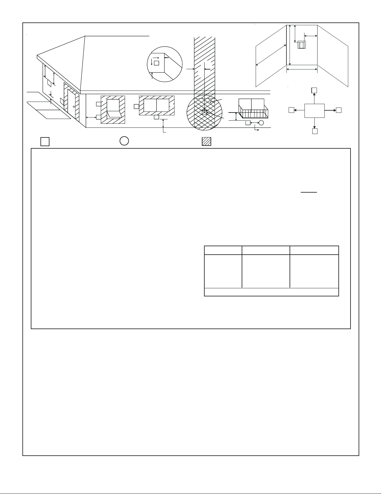
Page 31
V
M
N
G
v
D
E
v
B
L
v
B
v
F
v
A
B
v
B
v
A
= VENT TERMINAL
V
A = 12" ....................... clearances above grade, veran-
(See Note 1)
X
= AIR SUPPLY INLET
da, porch, deck or balcony
B = 12" ....................... clearances to window or door
that may be opened, or to permanently closed window.
D* = 18" ....................... vertical clearance to unventilat-
ed soffit or to ventilated soffit located above the terminal
*36” ...................... for vinyl clad soffits and below
electrical service
F = 9" ........................ clearance to outside corner
G = 6" ......................... clearance to inside corner
H = 3 ft. (Canada) ...... not to be installed above a gas
meter/regulator assembly within
3 feet (90cm) horizontally from the
center-line of the regulator
I = 3 ft. (U.S.A.)
6 ft. (Canada) ...... clearance to gas service regu-
lator vent outlet
J = 9" (U.S.A.)
12" (Canada) ........ clearance to non-mechanical air
supply inlet to building or the
combustion air inlet to any other
appliance
R
H
U.S.
(3 FT)
M
I
X
v
J or K
P
Q
(See Note 2)
S
Electrical
V
V
T
Service
D*
V
S
= AREA WHERE TERMINAL IS NOT PERMITTED
K = 3 ft. (U.S.A.)
6 ft. (Canada) ......... clearance to a mechanical
air supply inlet
L** = 7 ft. ......................... clearance above paved
(See Note 1)
sidewalk or a paved driveway
located on
public property
M*** = 18" ......................... clearance under veranda,
porch, deck, balcony or overhang
36” ......................... vinyl
N = 6” ........................... non-vinyl sidewalls
12” ......................... vinyl sidewalls
P = 8 ft.
Q
______________________________________________________________________
1 cap 3 feet 2 x Q
______________________________________________________________________
2 caps 6 feet 1 x Q
______________________________________________________________________
3 caps 9 feet 2/3 x Q
______________________________________________________________________
MIN
4 caps 12 feet 1/2 x Q
Q
= # termination caps x 3 R
MIN
= (2 / # termination caps) x Q
MAX
R
MAX
ACTUAL
ACTUAL
ACTUAL
ACTUAL
ACTUAL
S = 6" .......................... clearance from sides of elec-
(See Note 5)
trical service
T = 12" ......................... clearance above electrical
(See Note 5)
service
** a vent shall not terminate directly above a sidewalk or paved
driveway which is located between two single family dwellings
and serves both dwellings.
*** only permitted if veranda, porch, deck or balcony is fully open on
a minimum of 2 sides beneath the floor, or meets Note 2.
NOTE 1: On private property where termination is less than 7 feet
above a sidewalk, driveway, deck, porch, veranda or balcony, use of
a listed cap shield is suggested.
NOTE 2: Termination in an alcove space (spaces open only on one side
and with an overhang) are permitted with the dimensions specified for
vinyl or non-vinyl siding and soffits. 1. There must be 3 feet minimum
between termination caps. 2. All mechanical air intakes within 10 feet
of a termination cap must be a minimum of 3 feet below the termination
cap. 3. All gravity air intakes within 3 feet of a termination cap must be
a minimum of 1 foot below the termination cap.
Figure 29. Vent Termination Minimum Clearances
NOTE 3: Local codes or regulations may require different
clearances.
NOTE 4: T ermination caps may be hot. Consider their proximity to
doors or other traffic areas.
NOTE 5: Location of the vent termination must not interfere with
access to the electrical service.
WARNING: In the U.S: V ent system termination is NOT permitted
in screened porches. You must follow side wall, overhang and
ground clearances as stated in the instructions.
In Canada: Vent system termination is NOT permitted in screened
porches. Vent system termination is permitted in porch areas
with two or more sides open. You must follow all side walls,
overhang and ground clearances as stated in the instructions.
Heat & Glo assumes no responsibility for the improper performance of the fireplace when the venting system does not meet
these requirements.
CAUTION: IF EXTERIOR WALLS ARE FINISHED WITH VINYL SIDING, IT IS SUGGESTED THAT A VINYL PROTECTOR KIT BE
INSTALLED.
31
Page 32

For Vertical Terminations - T o locate the vent and install
V
the vent sections:
• Locate and mark the vent centerpoint on the underside
of the roof, and drive a nail through the centerpoint.
• Make the outline of the roof hole around the centerpoint
nail.
• The size of the roof hole framing dimensions depend on the
pitch of the roof. There MUST BE a 1-inch (25.4mm) clearance from the vertical vent pipe to combustible materials.
• Mark the roof hole accordingly.
T o seal the roof hole, and to divert rain and snow from the
vent system:
• Attach a flashing to the roof using nails, and use a nonhardening mastic around the edges of the flashing base
where it meets the roof.
• Attach a storm collar over the flashing joint to form a
water-tight seal. Place non-hardening mastic around the
joint, between the storm collar and the vertical pipe.
• Slide the termination cap over the end of the vent pipe
and snap into place.
• Cover the opening of the installed vent pipes.
• Cut and frame the roof hole.
• Use framing lumber the same size as the roof rafters
and install the frame securely . Flashing anchored to the
frame must withstand heavy winds.
• Continue to install concentric vent sections up through
the roof hole (for inside vent installations) or up past the
roof line until you reach the appropriate distance above
the roof (for outside terminations).
WARNING: MAJOR U.S. BUILDING CODES
!
SPECIFY MINIMUM CHIMNEY AND/OR
VENT HEIGHT ABOVE THE ROOF TOP. THESE MINIMUM HEIGHTS ARE NECESSARY IN THE INTEREST OF SAFETY . SEE THE FOLLOWING DIAGRAM
FOR MINIMUM HEIGHTS, PROVIDED THE TERMINA TION CAP IS A T LEAST 20 INCHES FROM A VERTICAL WALL AND 2-FEET BELOW A HORIZONT AL
OVERHANG.
NOTE: This also pertains to vertical vent systems installed on the outside of the building.
2 FT.
MIN.
TERMINATION
CAP
20 INCH MIN.
LOWEST
DISCHARGE
OPENING
12
H (MIN.) - MINIMUM HEIGHT FROM ROOF
TO LOWEST DISCHARGE OPENING
Roof Pitch H (min.) ft.
flat to 6/12 1.0
6/12 to 7/12 1.25
over 7/12 to 8/12 1.5
over 8/12 to 9/12 2.0
over 9/12 to 10/12 2 .5
over 10/12 to 1 1/12 3.25
over 1 1/12 to 12/12 4.0
over 12/12 to 14/12 5.0
over 14/12 to 16/12 6.0
over 16/12 to 18/12 7.0
over 18/12 to 20/12 7.5
over 20/12 to 21/12 8.0
HORIZONTAL
OVERHANG
ERTICAL
WALL
X
ROOF PITCH
IS X/ 12
Figure 30. Minimum Height from Roof to
Lowest Discharge Opening
32
Page 33

Step 4. Positioning, Leveling, and Securing
the Fireplace
The diagram below shows how to properly position, level,
and secure the fireplace.
Step 5. The Gas Control System
WARNING: THIS UNIT IS NOT FOR USE WITH
!
SOLID FUEL.
NAILING
TABS
(BOTH SIDES)
IPI PILOT
FLAME
SENSOR
ROD
Figure 32. Gas Control System
Intermittent Pilot Ignition (IPI) System
This system includes a 3V control valve, electronic module
and intermittent pilot.
WARNING: CONTINUOUS 110-120 VAC
!
SERVICE MUST BE WIRED DIRECTLY TO
THE FIREPLACE JUNCTION BOX IN A IPI SYSTEM.
Figure 31. Proper Positioning, Leveling, and
Securing of a Fireplace
• Place the fireplace into position.
• Level the fireplace from side to side and from front to
back.
• Shim the fireplace with non-combustible material, such
as sheet metal, as necessary.
• Secure the fireplace to the framing by nailing or screwing.
• Holes are provided in the base pan for securing the unit
to the floor.
33
Page 34

Step 6. The Gas Supply Line
NOTE: Have the gas supply line installed in accordance
with local building codes by a qualified installer
approved and/or licensed as required by the locality .
(In the Commonwealth of Massachusetts installation
must be performed by a licensed plumber or gas
fitter).
NOTE: Before the first firing of the fireplace, the gas
supply line should be purged of any trapped air.
NOTE: Consult local building codes to properly size
the gas supply line leading to the 1/2 inch
(13 mm) hook-up at the unit.
This gas fireplace is designed to accept a 1/2 inch
(13 mm) gas supply line. To install the gas supply line:
• A listed (and Commonwealth of Massachusetts approved)
1/2 inch (13mm) tee-handle manual shut-off valve and a
listed flexible gas connector are connected to the 1/2
inch (13mm) inlet of the control valve. NOTE: If substituting for these components, please consult local codes
for compliance.
• Locate the gas line access hole in the outer casing of
the fireplace.
• The gas line may be run from either side of the fireplace
provided the hole in the outer wrap does not exceed 2” in
diameter and it does not penetrate the actual firebox.
• Open the fireplace lower grille, insert the gas supply line
through the gas line hole, and connect it to the shut-off
valve.
• When attaching the pipe, support the control so that the
lines are not bent or torn.
• After the gas line installation is complete, all connections must be tightened and checked for leaks with a
commercially-available, non-corrosive leak check solution. Be sure to rinse off all leak check solution following
testing.
WARNING: DO NOT USE AN OPEN FLAME
!
TO CHECK FOR GAS LEAKS.
• Insert insulation from the outside of the fireplace and
pack the insulation tightly to totally seal between the
pipe and the outer casing.
• At the gas line access hole the gap between the supply
piping and gas access hole can be plugged with noncombustible insulation to prevent cold air infiltration.
USE A WRENCH ON
SHUT-OFF VALVE
WHEN TIGHTENING
GAS LINE.
MANUAL
SHUT-OFF
VALVE
FLEX CONNECTOR
GAS VALVE
GAS LINE
ACCESS
CONTROL VALVE
Figure 33. Gas Supply Line
Step 7. Gas Pressure Requirements
Pressure requirements for Heat & Glo gas fireplaces
are shown in the table below .
Pressure Natural Gas Propane
Minimum 5.0 inches 11.0 inches
Inlet Pressure w .c. w.c.
Maximum Inlet 14.0 inches 14.0 inches
Gas Pressure w.c. w.c.
Manifold 3.5 inches 10.0 inches
Pressure w .c. w.c.
A one-eighth (1/8) inch (3 mm) N.P.T. plugged tapping is
provided on the inlet and outlet side of the gas control for a
test gauge connection to measure the manifold pressure.
The fireplace and its individual shut-off valve must be
disconnected from the gas supply piping system during
any pressure testing of the system at test pressures in
excess of one-half (1/2) psig (3.5 kPa).
The fireplace must be isolated from the gas supply piping
system by closing its individual shut-off valve during any
pressure testing of the gas supply piping system at test
pressures equal to or less than one-half (1/2) psig (3.5 kPa).
34
Page 35

PLUG-IN
3V TRANSFORMER
ON/OFF
WALL SWITCH
VALVE
NEUTRAL
IGNITION
MODULE
(3V)
LOW VOL TAGE
GROUND
FLAME SPARKER/
SENSOR
SEE NOTE 1
REMOTE
CONTROL
HOT
ELECT R ON I C EM B E RS
BULB SOCKET
ASSEMBLY (3)
BLK
WHT
WHT
WHT
IGNITION MODULE 3 VAC
BLK
BLK
TERMINAL BLOC K
SCALE 1/1
I
S
WHT
ORG
GROUND TO
FIREPLACE
CHASSIS
BRN
BRN
ORG
INTERMITTENT
PILOT IGNITOR
GRN
Note: An alternate electronic ember
switch can be installed on the wall
by connecting a minimum 18 gage
Romex™ to the leads supplied on
the back of the electric ember
switch.
BLACK WIRE CAN BE
PLUGGED INTO ANY OF
#1 - #5 LOCATIONS
ON THE HOT SIDE
BLK
Figure 34. Intermittent Pilot Ignition
(IPI) Wiring Diagram
Step 8. Wiring the Fireplace
NOTE: Electrical wiring must be installed by a licensed
electrician.
CAUTION: DISCONNECT REMOTE CONTROLS IF ABSENT FOR EXTENDED TIME PERIODS. THIS WILL PREVENT ACCIDENT AL FIREPLACE OPERA TION.
For Intermittent Pilot Ignition Wiring
Appliance Requirements
This appliance requires that 1 10-120 VAC be wired to the
junction box. Maintain correct polarity when wiring the junction box.
FLAME ON/OFF
TRANSFORMER
WHT
WHITE WIRE
CAN BE
PLUGGED
INTO ANY
OF #1 - #5
LOCATIONS
ON THE
NEUTRAL
SIDE
PLUG IN
3 VAC
VALVE
LCOR & RCOR JUNCTION BOX
Operation using Battery Power
This fireplace has an optional battery operation. The system is fully functional with the use of two “D” size batteries
without ordinary 1 10-120 V AC power.
Wiring to the battery pack should be left disconnected in
order to conserve battery life. In the case of a loss of power,
simply connect red and black wire leads to activate battery
power (connect red to red, black to black). The fireplace can
be used as necessary . Once power (110 V AC) is restored,
disconnect red and black wire leads to extend battery life.
W ARNING
Wire 110V to electrical junction box.
Do NOT wire 1 10V to valve.
Do NOT wire 110V to wall switch.
• Incorrect wiring will damage millivolt valves.
• Uninterrupted or continuous power is required at all times
in IPI system
• Incorrect wiring will override IPI safety lockout and may
cause explosion.
EXCEPT when using battery back-up.
35
Page 36

TEMPERATURE
SENSO R SWITC H
SPEED CONTROL
(RHEOSTAT)
Figure 35. Fan Wiring Diagram
FAN
JUNCTION
BOX
SEE DETAIL A
NOTE: If any of the original wire as supplied with
the appliance must be replaced, it must be replaced
with the type 105oC rated wire.
DETAIL A
SCALE 1/1
Optional Accessories
Optional fan and remote control kits require that 110-120
VAC be wired to the factory installed junction box before
the fireplace is permanently installed.
Fan Installation
Recommended fan locations for the type of fireplace you
have (see Figures 36 and 37).
Wall Switch
Position the wall switch in the desired position on a wall.
Run a maximum of 25 feet (7.8 m) or less length of 18 A.W .G .
minimum wire and connect it to the fireplace ON/OFF switch
pigtails.
CAUTION: LABEL ALL WIRES PRIOR TO DISCONNECTION WHEN SERVICING CONTROLS. WIRING ERRORS
CAN CAUSE IMPROPER AND DANGEROUS OPERA TION.
VERIFY PROPER OPERATION AFTER SERVICING.
FAN
Figure 36. Corner fan location
Corner fan location
It is recommended to position the fan in this location as
shown. This will provide the best air flow (see Figure 36).
FAN
Figure 37. ST & PIER fan location
ST & Pier fan location
It is recommended to position the fan on the same side of
the fireplace as the vent collars are on. This will provide the
best air flow (see Figure 37).
36
Page 37

Step 9. Finishing
Figures 38 and 39 show the minimum vertical and corresponding
maximum horizontal dimensions of fireplace mantels or other
combustible projections above the top front edge of the fireplace. See
Figures 4 and 5 for other fireplace clearances. Only non-combustible
materials may be used to cover the black fireplace front.
WARNING: WHEN FINISHING THE FIREPLACE, NEVER
!
OBSTRUCT OR MODIFY THE AIR INLET/OUTLET GRILLES
IN ANY MANNER.
MANTEL
8”
7”
6”
5”
4”
3”
2”
1”
7”
6”
5”
HOOD
10”
9”
8”
*
12”
11”
10”
9”
16”
15”
14”
13”
12”
11”
NOTE: 12” mantel
at 16” above hood.
Mantel dimensions shown are
*
for standard hood on models:
PIER-HVB-IPI, LCOR-HVBIPI, and RCOR-HVB-IPI.
To use mantel dimensions
*
shown the fireplace must have
the standard hood replaced
with a larger hood (060-143)
on model: ST-HVB-IPI.
CAUTION: IF JOINTS BETWEEN THE FINISHED WALLS AND THE FIREPLACE SURROUND (TOP AND SIDES) ARE SEALED, A
300° F. MINIMUM SEALANT MATERIAL
MUST BE USED. THESE JOINTS ARE NOT
REQUIRED TO BE SEALED. ONLY NONCOMBUSTIBLE MATERIAL (USING 300° F.
MINIMUM ADHESIVE, IF NEEDED) CAN BE
APPLIED AS FACING TO THE FIREPLACE
SURROUND. SEE THE DIAGRAM BELOW .
NOTE: Sheetrock or other combustible
material such as wood can be placed on
the top edge and sides of the fireplace.
ST-HVB-IPI
TOP EDGE
SIDE EDGE
0” GAP
PIER-HVB-IPI and L&RCOR-HVB-IPI
TOP EDGE
SIDE EDGE
Figure 38.
Minimum Vertical and Maximum Horizontal
Dimensions of Combustibles above Fireplace
MANTEL
7”
6”
5”
4”
3”
2”
1”
17”
16”
15”
14”
13”
12”
HOOD
*
12”
11”
10”
9”
8”
21”
20”
19”
18”
Mantel dimensions shown are
*
for standard hood on model:
ST-HVB-IPI
23”
22”
NOTE: 12” mantel at
23” above hood.
0” GAP
Figure 40. Sealant Material
Hearth Extensions
A hearth extension may be desirable for
aesthetic reasons. However, ANSI or CAN/CGA
testing standards do not require hearth
extensions for gas fireplace appliances.
HOOD CLIP
Figure 39.
Minimum Vertical and Maximum Horizontal
Dimensions of Combustibles above Fireplace
37
Figure 41. Hood Clip
Page 38

Step 10. Installing T rim, Logs & Ember Material
Installing the Trim
Combustible materials may be brought up to the specified
clearances on the side and top front edges of the fireplace,
but MUST NEVER overlap onto the front face. The joints
between the finished wall and the fireplace top and sides
can only be sealed with a 300° F . (149° C) minimum sealant.
WARNING: WHEN FINISHING THE FIREPLACE,
!
NEVER OBSTRUCT OR MODIFY THE AIR INLET/
OUTLET GRILLES IN ANY MANNER.
Install optional marble and brass trim surround kits as
desired. Marble, brass, brick, tile, or other non-combustible
materials can be used to cover up the gap between
combustible material (sheetrock or wood) and the fireplace.
Do not obstruct or modify the air inlet/outlet grilles. When
overlapping on both sides, leave enough space so that the
bottom grille can be lowered and the trim door removed.
Positioning the Logs
If the gas logs have been factory installed they should not
need to be positioned. If the logs have been packaged
separately, refer to the instructions that accompany the
logs. Save the log instructions with this manual.
If sooting occurs, the logs might need to be repositioned
slightly to avoid excessive flame impingement.
Attachment of Lower Louver Assembly
This unit is shipped with the lower louver assembly attached
midway up the glass frame to assist in the set-up of the
unit. After the gas and electrical have been run, the louver
can be moved to it’s lower position as shown in Figure 42.
SHOULDER
BOLT
LOWER
LOUVER
DOOR
Figure 42. Lower louver assembly
Shutter Settings
___________________________________________
PIER-HVB-IPI 3/8” FULL OPEN
___________________________________________
ST-HVB-IPI 3/8” FULL OPEN
___________________________________________
NG LP
L&RCOR-HVB-IPI 3/8” FULL OPEN
Glass Specifications
Model Type
PIER-HVB-IPI TEMPERED
ST-HVB-IPI TEMPERED
L&RCOR-HVB-IPI TEMPERED
Heat & Glo fireplaces manufactured with tempered glass
may be installed in hazardous locations such as bathtub
enclosures as defined by the CPSC. The tempered glass
has been tested and certified to the requirements of ANSI
Z97.1-1984 and CPSC 16 CFR 1202. (Safety Glazing Certification Council SGCC # 1595 and 1597. Architectural T esting, Inc. Reports 02-31919.01 and 02-31917.01.)
This statement is in compliance with CPSC 16 CFR Section 1201.5 “Certification and labeling requirements” which
refers to 15 USC 2063 stating “…Such certificate shall accompany the product or shall otherwise be furnished to any
distributor or retailer to whom the product is delivered.”
Some local building codes require the use of tempered glass
with permanent marking in such locations. Glass meeting
this requirement is available from the factory . Please contact your dealer or distributor to order.
38
Page 39

Placing the Ember Material
Ember material is shipped with this gas fireplace. The bag
labeled Glowing Ember (050-721) is standard glowing ember material.
Optional Ember Light Kit (Emberkit-MS)
Ember Light Bulb Replacement
In the lower gas valve compartment you will find three access panels for the three light bulbs (see Figure 44).
T o place the ember material:
• Remove the wing nuts and glass clips or tension springs
around the glass door.
• Remove the glass door from the unit.
• Remove the grate and log set by removing the screws.
• Place dime size pieces of ember material about 1/2 inch
apart near port holes in burner top. Do NOT press embers into burner ports. Cover the top of the burner with a
single layer of ember material.
• Save the remaining ember materials for use during fireplace servicing. The bag of embers provided is sufficient
for 3 to 5 applications.
• Replace the glass door and a front trim door on the unit.
ACCESS PANEL
Figure 44.
Using a 5/16” nut driver remove the two bolts (see
Figure 45 ).
ACCESS PANEL
Figure 43 Placement of the Ember Material
Figure 45
Pull the access panel to expose the light bulb. Wearing
clean cotton gloves replace the bulb. Any skin oils which
get on a new bulb will greatly shorten the life of the bulb.
The bulb can be cleaned with isopropyl alcohol (see Figure 46).
Figure 46.
39
Page 40

Step 1 1. Before Lighting the Fireplace
Before lighting the fireplace, be sure to do the following:
• Remove the rubber bands from the log set (see Figure
47).
RUBBER
BANDS
A small amount of air will be in the gas supply lines. When
first lighting the fireplace, it will take a few minutes for the
lines to purge themselves of this air. Once the purging is
complete, the fireplace will light and will operate normally .
Subsequent lightings of the fireplace will not require this
purging of air from the gas supply lines, unless the gas
valve has been turned to the OFF position, in which
case the air would have to be purged.
NOTE: The fireplace should be run 3 to 4 hours on the
initial start-up. T urn it off and let it cool completely . Remove
and clean the glass. Replace the glass and run the fireplace
for an additional 8 hours. This will help to cure the products
used in the paint and logs.
FOAM
PADS
Figure 47.
• Remove the two foam pads which support the log set
and grate and allow the log set and grate to rest on the
base pan.
• Install the Lava Rock (supplied) to the firebox base pan
being careful not to cover the burner with the Lava Rock.
Remove all paperwork from underneath the fireplace.
Review safety warnings and cautions
• Read the Safety and Warning Information section at
the beginning of this Installers Guide.
Double-check for gas leaks
• Before lighting the fireplace, double-check the unit for
possible gas leaks.
Double-check vent terminations and front grilles for
obstructions.
• Before lighting the fireplace, double-check the unit for
possible obstructions that could be blocking the vent terminations or the front grilles.
Double-check for faulty components
• Any component that is found to be faulty MUST BE replaced with an approved component. T ampering with the
fireplace components is DANGEROUS and voids all warranties.
During this break-in period it is recommended that some
windows in the house be opened for air circulation. This will
help avoid setting off smoke detectors, and help eliminate
any odors associated with the fireplace’s initial burning.
Step 12. Lighting the Fireplace
You’ve reviewed all safety warnings, you’ve checked the
fireplace for gas leaks, you know the vent system is
unobstructed, and you’ve checked for faulty components.
Now you’re ready to light the fireplace.
WARNING: PLEASE REFER TO THE USER’S
!
MANUAL FOR ALL CAUTIONS, SAFETY , AND
WARNING INFORMATION PERTAINING TO THE
LIGHTING AND OPERA TION OF THE FIREPLACE.
After the Installation
LEAVE THIS INSTALLATION MANUAL WITH
!
THE APPLIANCE FOR FUTURE REFERENCE.
40
Page 41

Maintaining and Servicing Your Fireplace
4
Fireplace Maintenance
Although the frequency of your fireplace servicing and maintenance will depend on use and the type of installation, you
should have a qualified service technician perform an appliance check-up at the beginning of each heating season.
See the table below for specific guidelines regarding each
fireplace maintenance task.
IMPORT ANT : TURN OFF THE GAS BEFORE SERVICING
YOUR FIREPLACE.
Replacing old ember material
Frequency: Once annually , during the checkup.
By: Qualified service technician.
Task: Brush away loose ember material near the burner.
Replace old ember material with new dime-size and shape
pieces of Golden Ember (GE-93) and Glowing Ember (050-
721). New ember material should be placed alternately on
top of the burner - a layer of Golden Ember, a layer of
Glowing Ember, and so on. Save the remaining ember
material and repeat this procedure at your next servicing.
For more information, see Placing Ember Material.
Cleaning Burner and Controls
Frequency: Once annually .
By: Qualified service technician.
Task: Brush or vacuum the control compartment, fireplace
logs and burner areas surrounding the logs.
Cleaning Flame Sensor Rod (IPI Systems)
Frequency: Periodically .
By: Qualified service technician.
Task: Make a visual check of the straight flame sensor rod.
Use emery cloth to carefully remove any existing white film
or deposits.
Checking Flame Patterns, Flame Height
Frequency: Periodically .
By: Qualified service technician/Home owner.
Task: Make a visual check of your fireplace’ s flame patterns.
Make sure the flames are steady - not lifting or floating.
See Figure 48. The flame sensor (IPI) tips should be covered
with flame. See Figure 32.
MAKE SURE THE FLAMES
ARE STEADY—NOT
LIFTING OR FLOATING.
Figure 48. Burner Flame Patterns
Checking Vent System
Frequency: Before initial use and at least annually
thereafter, more frequently if possible.
By: Qualified service technician/Home owner.
Task: Inspect the external vent cap on a regular basis to
ensure that no debris is interfering with the flow of air. Inspect
entire vent system for proper function.
Cleaning Glass Door
Frequency: After the first 3 to 4 hours of use. As neces-
sary after initial cleaning.
By: Home owner.
Task: Remove and clean glass after the first 3 to 4 hours of
use. Af ter the initial cleaning, clean as necessary , particularly after adding new ember (flame colorant) material. Film
deposits on the inside of the glass door should be cleaned
off using a household glass cleaner . NOTE: DO NOT handle
or attempt to clean the door when it is hot and DO
NOT use abrasive cleaners.
41
 Loading...