


Models:
FB-Grand
FB-IN
CFX-Grand-B
CFX-IN-B
Underwriters
Laboratories Listed
Installers Guide
WARNING: IF THE INFORMATION IN THESE INSTRUCTIONS IS NOT FOLLOWED EXACTLY, A FIRE OR EXPLOSION MAY RESULT CAUSING PROPERTY DAMAGE, PERSONAL INJURY, OR DEATH.
-Do not store or use gasoline or other flammable vapors and liquids in the vicinity of this or any other appliance.
-What to do if you smell gas
•Do not try to light any appliance.
•Do not touch any electrical switch.
•Do not use any phone in your building.
•Immediately call your gas supplier from a neighbor's phone. Follow the gas supplier's instructions.
•If you cannot reach your gas supplier, call the fire department.
-Installation and service must be performed by a qualified installer, service agency, or the gas supplier.
Printed in U.S.A. Copyright 2002,
Heat-N-Glo, a division of Hearth Technologies Inc. 20802 Kensington Boulevard, Lakeville, MN 55044
READ THIS MANUAL BEFORE INSTALLING OR OPERATING THIS APPLIANCE. THIS INSTALLERS GUIDE MUST BE LEFT WITH APPLIANCE FOR FUTURE REFERENCE.
WARNING: IMPROPER INSTALLATION, ADJUSTMENT, ALTERATION, SERVICE OR MAINTENANCE CAN CAUSE INJURY OR PROPERTY DAMAGE. REFER TO THIS MANUAL. FOR ASSISTANCE OR ADDITIONAL INFORMATION CONSULT A QUALIFIED INSTALLER, SERVICE AGENCY, OR THE GAS SUPPLIER.
1.This appliance may be installed in an aftermarket, permanently located, manufactured (mobile) home, where not prohibited by local codes.
2.This appliance is only for use with the type of gas indicated on the rating plate. This appliance is not convertible for use with other gases, unless a certified kit is used.
Please contact your Heat-N-Glo dealer with any questions or concerns. For the number of your nearest Heat-N-Glo dealer, please call 1-888-427-3973.
This product is covered by one or more of the following patents: (United States) 4,112,913; 4,408,594; 4,422,426; 4,424,792; 4,520,791; 4,793,322; 4,852,548; 4,875,464; 5,000,162; 5,016,609; 5,076,254 5,191,877; 5,218,953; 5,328,356; 5,429,495; 5,452,708; 5,542,407; 5,613,487; (Australia) 543790; 586383; (Canada) 1,123,296; 1,297,746; 2,195,264; (Mexico) 97-0457; (New Zealand) 200265; or other U.S. and foreign patents pending.
783-900C 12/02
1
SAFETY AND WARNING INFORMATION
READ and UNDERSTAND all instructions carefully ! before starting the installation. FAILURE TO
FOLLOW these installation instructions may result in a possible fire hazard and will void the warranty.
Prior to the first firing of the fireplace, READ the
! Using Your Fireplace section of the Owners Guide.
DO NOT USE this appliance if any part has been ! under water. Immediately CALL a qualified service
technician to inspect the unit and to replace any part of the control system and any gas control which has been under water.
! THIS UNIT IS NOT FOR USE WITH SOLID FUEL.
Installation and repair should be PERFORMED by a ! qualified service person. The appliance and venting
system should be INSPECTED before initial use and at least annually by a professional service person. More frequent cleaning may be required due to excessive lint from carpeting, bedding material, etc. It is IMPERATIVE that the unit’s control compartment, burners, and circulating air passageways BE KEPT CLEAN to provide for adequate combustion and ventilation air.
Always KEEP the appliance clear and free from
!combustible materials, gasoline, and other flammable vapors and liquids.
NEVER OBSTRUCT the flow of combustion and
!ventilation air. Keep the front of the appliance CLEAR of all obstacles and materials for servicing and proper operations.
Due to the high temperature, the appliance should
!be LOCATED out of traffic areas and away from furniture and draperies. Clothing or flammable material SHOULD NOT BE PLACED on or near the appliance.
Children and adults should be ALERTED to the
!hazards of high surface temperature and should STAY AWAY to avoid burns or clothing ignition. Young children should be CAREFULLY SUPERVISED when they are in the same room as the appliance.
These units MUST use one of the vent systems ! described in the Installing the Fireplace section of
the Installers Guide. NO OTHER vent systems or components MAY BE USED.
This gas fireplace and vent assembly MUST be
! vented directly to the outside and MUST NEVER be attached to a chimney serving a separate solid fuel burning appliance. Each gas appliance MUST USE a separate vent system. Common vent systems are
PROHIBITED.
INSPECT the external vent cap on a regular basis to ! make sure that no debris is interfering with the air
flow.
! The glass door assembly MUST be in place and  sealed, and the trim door assembly MUST be in
place on the fireplace before the unit can be placed into safe operation.
DO NOT OPERATE this appliance with the glass
!door removed, cracked, or broken. Replacement of the glass door should be performed by a licensed or qualified service person. DO NOT strike or slam the glass door.
The glass door assembly SHALL ONLY be
!replaced as a complete unit, as supplied by the gas fireplace manufacturer. NO SUBSTITUTE material may be used.
DO NOT USE abrasive cleaners on the glass door
!assembly. DO NOT ATTEMPT to clean the glass door when it is hot.
Turn off the gas before servicing this appliance. It is
!recommended that a qualified service technician
perform an appliance check-up at the beginning of each heating season.
Any safety screen or guard removed for servicing
!must be replaced before operating this appliance.
DO NOT place furniture or any other combustible
!household objects within 36 inches of the fireplace front.
2
TABLE OF CONTENTS |
|
|
Safety and Warning Information ............................................... |
2 |
|
u Service Parts Lists .................................................................... |
4 |
|
Section 1: Approvals and Codes ............................................ |
10 |
|
Appliance Certification ............................................................... |
10 |
|
Installation Codes ...................................................................... |
10 |
|
u High Altitude Installations ............................................................ |
10 |
|
Section 2: Getting Started ...................................................... |
11 |
|
Introducing the Heat-N-Glo Gas Appliances ............................... |
11 |
|
Pre-installation Preparation ........................................................ |
11 |
|
Venting and Installation ............................................................... |
11 |
|
Section 3: Installing the Insert ............................................... |
14 |
|
Step 1 |
Installing the Vent System ........................................... |
14 |
Step 2 |
Positioning, Leveling, and Securing the Insert ............. |
18 |
Step 3 |
The Gas Control Systems .......................................... |
18 |
Step 4 |
The Gas Supply Line .................................................. |
18 |
Step 5 |
Gas Pressure Requirements ...................................... |
19 |
Step 6 |
Wiring the Appliance ................................................... |
19 |
Step 7 |
Installing Logs and Ember Material ............................. |
21 |
|
Shutter Settings .......................................................... |
21 |
|
Positioning the Logs ................................................... |
21 |
|
Placing the Ember Material ......................................... |
21 |
Step 8 |
Installing Trim Surround .............................................. |
21 |
Step 9 |
Before Lighting the Appliance ...................................... |
22 |
Step 10 |
Lighting the Appliance ................................................. |
22 |
After the Installation .................................................................... |
22 |
|
Section 4: Maintaining and Servicing Your Appliance ........ |
23 |
|
u = Contains updated information. |
|
|
3

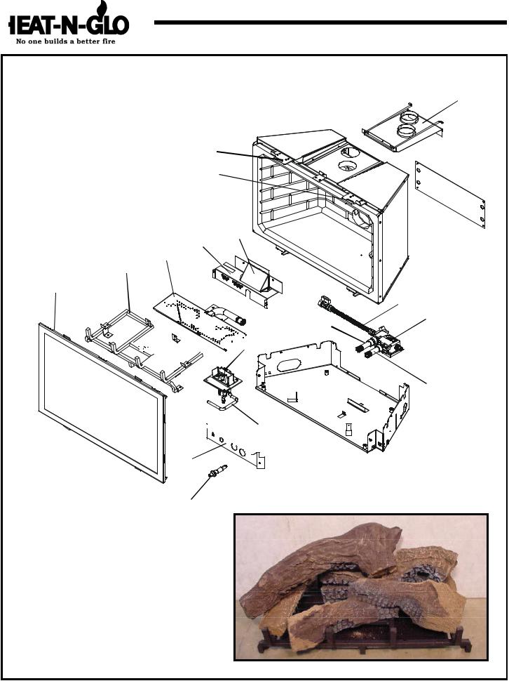
|
Service Parts |
FB-GRAND, CFX-GRAND-B |
|
|
(NG, LP) Exploded Parts Diagram |
CFX-Grand-B: Manufacturing Dates: 9-01 to 12-02 |
|
u |
(GN, PL) Vue éclatée des pièces |
FB-Grand-B: Manufacturing Dates:8-02 to _____ |
|
|
FB-GRAND SHOWN |
13 |
12 |
|
|
||
20 
 19
19 


21
1 |
3 |
2 |
22 |
16 |
9


 17
17
10 |


 18 11
18 11 


 15
15
14 
4 Log Set Assembly
*Part number list on following page.
*La liste des numéros de pièce se trouve à la page suivante.
8
5
6
7
4
(NG, LP) Service Parts List / Liste des pièces de rechange |
FB-GRAND |
IMPORTANT: THIS IS DATED INFORMATION. The most current information is located on your dealers VIP site. When ordering, supply serial and model numbers to ensure correct service parts. / IMPORTANT : L'information fournie dans cette brochure n'est valide que pendant une courte période. Les sites VIP des distributeurs disposent des renseignements les plus récents. Lors d'une commande, veuillez fournir les numéros de série et de modèles pour un remplacement adéquat des pièces.
|
ITEM / |
|
|
|
|
|
|
|
|
|
|
|
Description |
PART NUMBER |
|
|
PIÈCE |
|
|
|
|
|
|
|
|
|
|
|
/ N° DE PIÈCE |
||
|
|
|
|
|
|
|
|
|
|
|
|
|
|||
|
|
ON/OFF Rocker Switch / Interrupteur à bascule marche/arrêt |
680-528 |
||||||||||||
|
|
|
|
|
|
||||||||||
|
|
Burner Orifice NG (.125) |
/ |
Orifice de brûleur GN (.125) |
768-801 |
||||||||||
|
|
|
|
|
|
||||||||||
|
|
Burner Orifice LP (#49) |
/ |
Orifice de brûleur PL (#49) |
065-801 |
||||||||||
|
|
|
|
||||||||||||
|
1 |
Glass Door Assembly, Ceramic / Porte en verre |
GLA-FBG |
||||||||||||
|
|
|
|
|
|
|
|||||||||
|
2 |
Burner NG |
/ |
Brûleur GN |
|
778-176A |
|||||||||
|
|
|
|
|
|
|
|
||||||||
|
2 |
Burner LP |
/ |
Brûleur PL |
|
|
768-175A |
||||||||
|
|
|
|
|
|
||||||||||
|
3 |
Log Grate |
/ |
Grille de Bûche |
768-360A |
||||||||||
|
|
|
|
||||||||||||
|
4 |
Log Set Assembly / Jeu de Bûches |
LOGS-CFXGB |
||||||||||||
|
|
|
|
|
|
|
|
|
|
|
|||||
|
5 |
Log 1 |
/ |
Bûche 1 |
|
|
|
|
|
SRV768-701 |
|||||
|
|
|
|
|
|
|
|
|
|
|
|||||
|
6 |
Log 2 |
/ |
Bûche 2 |
|
|
|
|
|
SRV768-704 |
|||||
|
|
|
|
|
|
|
|
|
|
|
|||||
|
7 |
Log 3 |
/ |
Bûche 3 |
|
|
|
|
|
SRV768-705 |
|||||
|
|
|
|
|
|
|
|
|
|
||||||
|
8 |
Log 4 |
/ Bûche 4 |
|
|
|
|
|
SRV582-705 |
||||||
|
|
|
|
|
|
|
|
|
|||||||
|
9 |
Pilot Control Knob |
|
|
|
|
|
571-530 |
|||||||
|
|
|
|
|
|
|
|
||||||||
|
10 |
Flame Control Knob |
|
|
|
|
571-531 |
||||||||
|
|
|
|
|
|
|
|
|
|||||||
|
11 |
Valve Cover Plate |
|
|
|
|
|
768-120 |
|||||||
|
|
|
|
||||||||||||
u |
12 |
Air Passage: Slide Plate Assembly with Handle / |
783-108A |
||||||||||||
Assemblée de Plat de Diapositive(Glissade) avec Poignée |
|||||||||||||||
|
|
|
|||||||||||||
u |
13 |
Slide Plate Handle / |
|
Poignée de Plat de Diapositive(Glissade) |
768-351 |
||||||||||
|
|
|
|
|
|
|
|||||||||
|
14 |
Piezo Ignitor |
/ |
|
Allumage Piézo |
418-513 |
|||||||||
|
|
|
|
|
|
||||||||||
|
15 |
Burner Tube |
/ |
Tube de brûleur |
477-301A |
||||||||||
u |
|
|
|
|
|||||||||||
16 |
Flex Ball Valve Assembly |
/ Fléchir l'Assemblée de Soupape de Balle |
302-320A |
||||||||||||
|
|
|
|
|
|
|
|||||||||
|
17 |
Valve NG / |
Valve GN |
|
|
060-522 |
|||||||||
|
|
|
|
|
|
|
|
||||||||
|
17 |
Valve LP |
/ |
Valve PL |
|
|
060-523 |
||||||||
|
|
|
|
|
|
||||||||||
|
18 |
Pilot Assembly NG |
/ |
Module de veilleuse GN |
485-510A |
||||||||||
|
|
|
|
|
|
||||||||||
|
18 |
Pilot Assembly LP / |
|
Module de veilleuse PL |
485-511A |
||||||||||
u |
|
|
|
|
|
||||||||||
19 |
Glass Tab - Right |
/ |
Étiquette de Verre - Droit |
783-133 |
|||||||||||
u |
|
|
|
|
|||||||||||
20 |
Glass Tab - Left |
/ Étiquette de Verre - Gauche |
783-134 |
||||||||||||
u |
|
|
|
|
|||||||||||
21 |
Baffle - top |
/ Déconcertez le Sommet |
768-148 |
||||||||||||
u |
|
|
|
|
|||||||||||
22 |
Baffle - bottom / |
Déconcertez - le fond(bas) |
768-146 |
||||||||||||
|
|
|
|
|
|||||||||||
u |
|
Pilot Bracket Gasket |
/ Joint de Parenthèse Pilote |
768-432 |
|||||||||||
|
|
|
|
|
|
||||||||||
|
|
Pilot Orifice NG |
/ |
Orifice de veilleuse GN |
446-505 |
||||||||||
|
|
|
|
|
|
||||||||||
|
|
Pilot Orifice LP |
/ |
Orifice de veilleuse PL |
446-517 |
||||||||||
|
|
|
|
|
|||||||||||
|
|
Thermocouple |
/ Thermocouple |
446-511 |
|||||||||||
|
|
|
|
|
|
|
|
||||||||
|
|
Thermopile |
|
/ |
Thermopile |
|
060-512 |
||||||||
u |
|
|
|
|
|
||||||||||
|
Pilot Tube |
/ |
Tube de veilleuse |
SRV485-301 |
|||||||||||
|
|
|
|
|
|
|
|||||||||
|
|
Fan/Blower / |
Ventilateur |
|
|
GFK-160A |
|||||||||
|
|
|
|
||||||||||||
|
|
Junction Box (Required if installing blower) / Boîtier de dérivation (Exigé, s'installant la soufflerie) |
040-250A |
||||||||||||
|
|
|
|
|
|
||||||||||
|
|
Conversion Kit |
NG / |
Module de conversion GN |
NGK-FBG |
||||||||||
|
|
|
|
|
|
|
|||||||||
|
|
Conversion Kit LP |
/ |
|
Module de conversion PL |
LPK-FBG |
|||||||||
5
(NG, LP) Service Parts List / Liste des pièces de rechange |
CFX-GRAND-B |
IMPORTANT: THIS IS DATED INFORMATION. The most current information is located on your dealers VIP site. When ordering, supply serial and model numbers to ensure correct service parts. / IMPORTANT : L'information fournie dans cette brochure n'est valide que pendant une courte période. Les sites VIP des distributeurs disposent des renseignements les plus récents. Lors d'une commande, veuillez fournir les numéros de série et de modèles pour un remplacement adéquat des pièces.
|
ITEM / |
|
|
|
|
|
|
|
|
|
Description |
|
PART NUMBER |
||
|
PIÈCE |
|
|
|
|
|
|
|
|
|
|
/ N° DE PIÈCE |
|||
|
|
|
|
|
|
|
|
|
|
|
|
|
|
||
|
|
ON/OFF Rocker Switch / Interrupteur à bascule marche/arrêt |
|
680-528 |
|||||||||||
|
|
|
|
|
|
||||||||||
|
|
Burner Orifice NG (.125) |
/ Orifice de brûleur GN (.125) |
|
768-801 |
||||||||||
|
|
|
|
|
|
||||||||||
|
|
Burner Orifice LP (#49) / |
Orifice de brûleur PL (#49) |
|
065-801 |
||||||||||
|
|
|
|
|
|
|
|
|
|
|
|
|
|
|
|
|
1 |
Glass Door Assembly, Ceramic |
(NG) / |
Porte en verre |
PRE 002108516 |
GLA-CFXGB |
|||||||||
|
POST 002108516 |
GLA-FBG |
|||||||||||||
|
|
|
|
|
|
|
|
|
|
|
|
|
|
||
|
1 |
Glass Door Assembly, Ceramic |
(LP) / |
Porte en verre |
PRE 002106948 |
GLA-CFXGB |
|||||||||
|
POST 002106948 |
GLA-FBG |
|||||||||||||
|
|
|
|
|
|
|
|
|
|
|
|
|
|
||
|
2 |
Burner NG |
/ |
Brûleur GN |
|
|
|
|
778-176A |
||||||
|
|
|
|
|
|
|
|
|
|
||||||
|
2 |
Burner LP |
/ |
Brûleur PL |
|
|
|
|
768-175A |
||||||
|
|
|
|
|
|
|
|
|
|||||||
|
3 |
Log Grate |
/ |
Grille de Bûche |
|
|
|
768-360A |
|||||||
|
|
|
|
|
|
|
|||||||||
|
4 |
Log Set |
Assembly / Jeu de Bûches |
|
|
LOGS-CFXGB |
|||||||||
|
5 |
Log 1 |
/ |
Bûche 1 |
|
|
|
|
|
|
SRV768-701 |
||||
|
6 |
Log 2 |
/ |
Bûche 2 |
|
|
|
|
|
|
SRV768-704 |
||||
|
|
|
|
|
|
|
|
|
|
|
|
||||
|
7 |
Log 3 |
/ |
Bûche 3 |
|
|
|
|
|
|
SRV768-705 |
||||
|
|
|
|
|
|
|
|
|
|
|
|
||||
|
8 |
Log 4 |
/ |
Bûche 4 |
|
|
|
|
|
|
SRV582-705 |
||||
|
|
|
|
|
|
|
|
|
|
||||||
|
9 |
Pilot Control Knob |
|
|
|
|
|
|
571-530 |
||||||
|
|
|
|
|
|
|
|
|
|||||||
|
10 |
Flame Control Knob |
|
|
|
|
|
571-531 |
|||||||
|
|
|
|
|
|
|
|
|
|
||||||
|
11 |
Valve Cover Plate |
|
|
|
|
|
|
768-120 |
||||||
|
|
|
|
|
|||||||||||
u |
12 |
Air Passage: Slide Plate Assembly with Handle / |
|
783-108A |
|||||||||||
Assemblée de Plat de Diapositive(Glissade) avec Poignée |
|
||||||||||||||
|
|
|
|
||||||||||||
u |
13 |
Slide Plate Handle / |
Poignée de Plat de Diapositive(Glissade) |
|
768-351 |
||||||||||
|
|
|
|
|
|
|
|
|
|||||||
|
14 |
Piezo Ignitor / |
|
Allumage Piézo |
|
|
|
418-513 |
|||||||
|
|
|
|
|
|
|
|
|
|||||||
|
15 |
Burner Tube |
/ |
Tube de brûleur |
|
|
|
477-301A |
|||||||
|
|
|
|
|
|
||||||||||
u |
16 |
Flex Ball Valve Assembly |
/ Fléchir l'Assemblée de Soupape de Balle |
|
302-302A |
||||||||||
|
|
|
|
|
|
|
|
|
|
||||||
|
17 |
Valve NG |
/ |
Valve GN |
|
|
|
|
060-522 |
||||||
|
|
|
|
|
|
|
|
|
|
|
|||||
|
17 |
Valve LP |
|
/ |
Valve PL |
|
|
|
|
060-523 |
|||||
|
|
|
|
|
|
||||||||||
|
18 |
Pilot Assembly NG / |
Module de veilleuse GN |
|
485-510A |
||||||||||
|
|
|
|
|
|
||||||||||
|
18 |
Pilot Assembly LP / |
Module de veilleuse PL |
|
485-511A |
||||||||||
u |
|
|
|
|
|
|
|||||||||
19 |
Glass Tab - right |
/ |
Étiquette de Verre - droit |
|
783-133 |
||||||||||
u |
|
|
|
|
|
||||||||||
20 |
Glass Tab - Left |
/ Étiquette de Verre - Gauche |
|
783-134 |
|||||||||||
|
|
|
|
|
|
|
|||||||||
u |
21 |
Baffle Top |
/ Déconcertez le Sommet |
|
|
786-148 |
|||||||||
u |
22 |
Baffle - bottom / |
Déconcertez - le fond(bas) |
|
768-146 |
||||||||||
u |
|
|
|
|
|
||||||||||
|
Pilot Bracket Gasket |
/ Joint de Parenthèse Pilote |
|
768-432 |
|||||||||||
|
|
|
|
|
|
|
|||||||||
|
|
Pilot Orifice NG |
/ |
Orifice de veilleuse GN |
|
446-505 |
|||||||||
|
|
|
|
|
|
|
|||||||||
|
|
Pilot Orifice LP |
/ |
Orifice de veilleuse PL |
|
446-517 |
|||||||||
|
|
|
|
|
|
|
|
|
|||||||
|
|
Thermocouple |
/ |
Thermocouple |
|
|
|
446-511 |
|||||||
|
|
|
|
|
|
|
|
|
|
||||||
|
|
Thermopile |
/ |
Thermopile |
|
|
|
|
060-512 |
||||||
|
|
|
|
|
|
|
|
|
|||||||
|
|
Pilot Tube |
/ |
Tube de veilleuse |
|
|
|
SRV485-301 |
|||||||
|
|
|
|
|
|
|
|
||||||||
|
|
Junction Box |
/ |
Boîtier de dérivation |
|
|
040-250A |
||||||||
|
|
|
|
|
|||||||||||
|
|
Conversion Kit NG / Module de conversion GN |
|
NGK-CFXGB |
|||||||||||
|
|
Conversion Kit LP / Module de conversion PL |
|
LPK-CFXGB |
|||||||||||
6
Service Parts
(NG, LP) Exploded Parts Diagram (GN, PL) Vue éclatée des pièces
FB-IN, CFX-IN-B
CFX-IN-B: Manufacturing Dates: 12-02 to 9-01 FB-IN: Manufacturing Dates: 8-02 to ____
u
FB-IN SHOWN |
12 |
|
20
19
21
22
2 3
1
|
16 |
9 |
17 |
|


 18
18
10

 15
15
11
14 |
4 Log Set Assembly |
|
|
8 |
5 |
|
|
|
* Part number list on following page. |
6 |
7 |
* La liste des numéros de pièce se trouve |
|
|
à la page suivante. |
|
|
7
 Loading...