

Heat & Glo LifeStyle BW36 User Manual
Heat-N-Glo, a Division of Hearth Technologies Inc.
20802 Kensington Blvd.
Lakeville, MN 55044
BW36 BW36C
WOODBURNING FIREPLACE
INSTALLATION & OPERATING
INSTRUCTIONS
FOR RESIDENTIAL USE
Model BW36 shown. 558-900-D-4/00
No one builds a better fire

4-00 2 30491D
BW36 SERIES WOODBURNING FIREPLACE
Table of Contents
A. Listings and Code Approvals..........................................................................................................................3
B. Description of the Fireplace System...............................................................................................................3
C. Fireplace System Components ......................................................................................................................4
D. Pre-Installation Preparation............................................................................................................................8
1. Fireplace Locations and Space Requirements.........................................................................................8
2. Framing The Fireplace.............................................................................................................................9
3. Hearth Extensions..................................................................................................................................10
4. Sidewalls/Surrounds...............................................................................................................................11
5. Mantel.....................................................................................................................................................11
E. Chimney Requirements................................................................................................................................11
1. Using Offsets and Returns.....................................................................................................................12
2. Chimney Height Requirements ..............................................................................................................13
F. Step-By-Step Installation of the Fireplace System .......................................................................................14
G. Constructing a Chase...................................................................................................................................19
1. Materials For The Chase........................................................................................................................19
2. Installing a Terminal Cap on a Chase-Enclosed Chimney.....................................................................20
H. Operating Instructions ..................................................................................................................................21
Safety Precautions
1. Please read these installation instructions com-
pletely before beginning installation procedures.
Failure to follow them could cause a fireplace
malfunction resulting in serious injury and/or property damage.
2. Always check your local Building codes prior to
installation. The installation must comply with all
local, regional, state and national codes and regulations.
3. An adequate supply of replacement combustion
air from outside the house must be available to
the fire for the fireplace to operate properly. To
achieve this, an optional outside air kit is highly
recommended.
In the event the home is unusually tight, the
optional combustion air kit may not provide all the
air required to support combustion. Heat-N-Glo is
not responsible for any smoking or related problems that may result from the lack of adequate
combustion air. It is the responsibility of the
builder/contractor to ensure that adequate combustion air has been provided for the fireplace.
4. The BW36 Series woodburning fireplace must be
installed with the Hearth Technologies Inc. (HTI)
SL300 Series chimney system.
The chimney system must always terminate outside the Building. Be sure to follow all chimney
specifications given in these installation instructions.
5. NEVER leave children unattended when there is
a fire burning in the fireplace.
6. This fireplace is built for solid fuel only. DO NOT
use chimney cleaners or flame colorants in your
fireplace.
7. NEVER use gasoline, gasoline type lantern fuel,
kerosene, charcoal lighter fluid, or similar liquids
in this fireplace. Keep any flammable liquids a
safe distance from the fireplace.
8. The flue damper must be open at all times when
the fireplace is in use.
9. While servicing this fireplace, always shut off any
electricity or gas to the fireplace. This will prevent
possible electrical shock or burns. Also, make
sure the unit is completely cooled before servicing.
10. To ensure a safe fireplace system and to prevent
the buildup of soot and creosote, inspect and
clean the fireplace and chimney prior to use and
periodically during the burning season.
PLEASE RETAIN THIS MANUAL FOR FUTURE REFERENCE.
No one builds a better fire

The BW36 Series fireplace system has been tested
and listed in accordance with the UL127 Standards,
and has been listed by Underwriters Laboratories Inc.
for installation and operation in the United States as
described in these Installation & Operating
Instructions.
The BW36 Series fireplaces have been tested and
listed for use with the optional components given on
page 4. These optional components may be purchased separately and installed at a later date.
However, installation of an outside air kit will require
significant reconstruction, and should be installed at
the time of the initial fireplace installation.
Check with your local Building Code agency prior to
installing this fireplace to ensure compliance with local
Codes, including the need for permits and follow-up
inspections. If any assistance is required during
installation, please contact your local dealer or the
Heat-N-Glo Technical Services Department, 20802
Kensington Blvd., Lakeville, MN 55044.
Heat-N-Glo is a Division of Hearth Technologies Inc.
WARNING!
THIS HEAT-N-GLO FIREPLACE AND ITS COMPONENTS ARE DESIGNED TO BE
INSTALLED AND OPERATED AS A SYSTEM. ANY ALTERATION TO OR
SUBSTITUTION FOR ITEMS IN THIS SYSTEM, UNLESS ALLOWED BY THESE
INSTALLATION INSTRUCTIONS, WILL VOID THE UNDERWRITERS LABORATORIES
LISTING AND MAY VOID THE PRODUCT WARRANTY. IT MAY ALSO CREATE A
HAZARDOUS INSTALLATION.
READ THROUGH THESE INSTRUCTIONS THOROUGHLY BEFORE STARTING YOUR
INSTALLATION AND FOLLOW THEM CAREFULLY THROUGHOUT YOUR PROJECT!
The HEAT-N-GLO fireplace system consists of the following:
1. Fireplace/Integral Grate 3. Chimney System
2. Hearth Extension 4. Chimney Termination Cap
Optional components include:
1. Glass Doors 3. Heat Circulating Fans
2. Outside Combustion Air System
4-00 3 30491D
BW36 SERIES WOODBURNING FIREPLACE
A. LISTINGS AND CODE APPROVALS
B. DESCRIPTION OF THE FIREPLACE SYSTEM
NOTE: Illustrations throughout these
instructions reflect “typical installations”
and are for design purposes only. Actual
installation may vary slightly due to individual design preferences. However, minimum and maximum clearances must be
maintained at all times.
The illustrations and diagrams used
throughout these installation instructions
are not drawn to scale.
Tools and Building Supplies Normally
Required:
Tools Building Supplies
Saw Hearth Extension Material
Pliers Wall-finishing Materials
Hammer Framing Material
Phillips Screwdriver Fireplace Surround
Tape Measure Caulking Material
Plumb Line
Level
Electric Drill and Bits
Framing Square
No one builds a better fire
HTI Catalog # Description
BW36* Radiant Fireplace, includes integral grate and hearth protection strips
BW36C* Heat Circulating Fireplace, includes integral grate and hearth
protection strips
HX3 Hearth Extension
DM1036 Glass Doors - Original Series, Black
DM1036A Glass Doors - Original Series,Brushed Brass Finish
DM1036B Glass Doors - Original Series, Polished Brass Finish
GR16 Integral Grate (included with Fireplace)
AK22 Outside Air Kit
FK22 Fan Kit with electrical junction box (BW36C ONLY)
BC10 Fan motor rheostat control
JK9 Electrical Junction Box (BW36C ONLY)
ID4 Insulated Duct/Outside Air
UD4 Uninsulated Duct/Outside Air
SL306 Chimney Section - 6” long
SL312 Chimney Section - 12” long
SL318 Chimney Section - 18” long
SL324 Chimney Section - 24” long
SL336 Chimney Section - 36” long
SL348 Chimney Section - 48” long
SL3 Chimney Stabilizer
SL315 Chimney Offset/Return - 15°
SL330 Chimney Offset/Return - 30°
FS338 Firestop - Straight
FS339 Firestop - 15°
FS340 Firestop - 30°
AS8 SL300 Straight Attic Insulation Shield, 24"
JB877 Chimney Joint Band
CB876 Chimney Bracket
RF370 Roof Flashing - Flat to 6/12 Pitch
RF371 Roof Flashing - 6/12 to 12/12 Pitch
TR342 Telescoping Chimney Terminal Cap - Round
TR344 Chimney Terminal Cap - Round (Storm collar included)
ST375 Chimney Terminal Cap - Square
TS345 Chimney Terminal Cap - Square
TS345P Chimney Terminal Cap - Square (Painted)
CT35 Chase Top
LDS33 Decorative Shroud - 3’ x 3’
LDS46 Decorative Shroud - 4’ x 6’
4-00 4 30491D
BW36 SERIES WOODBURNING FIREPLACE
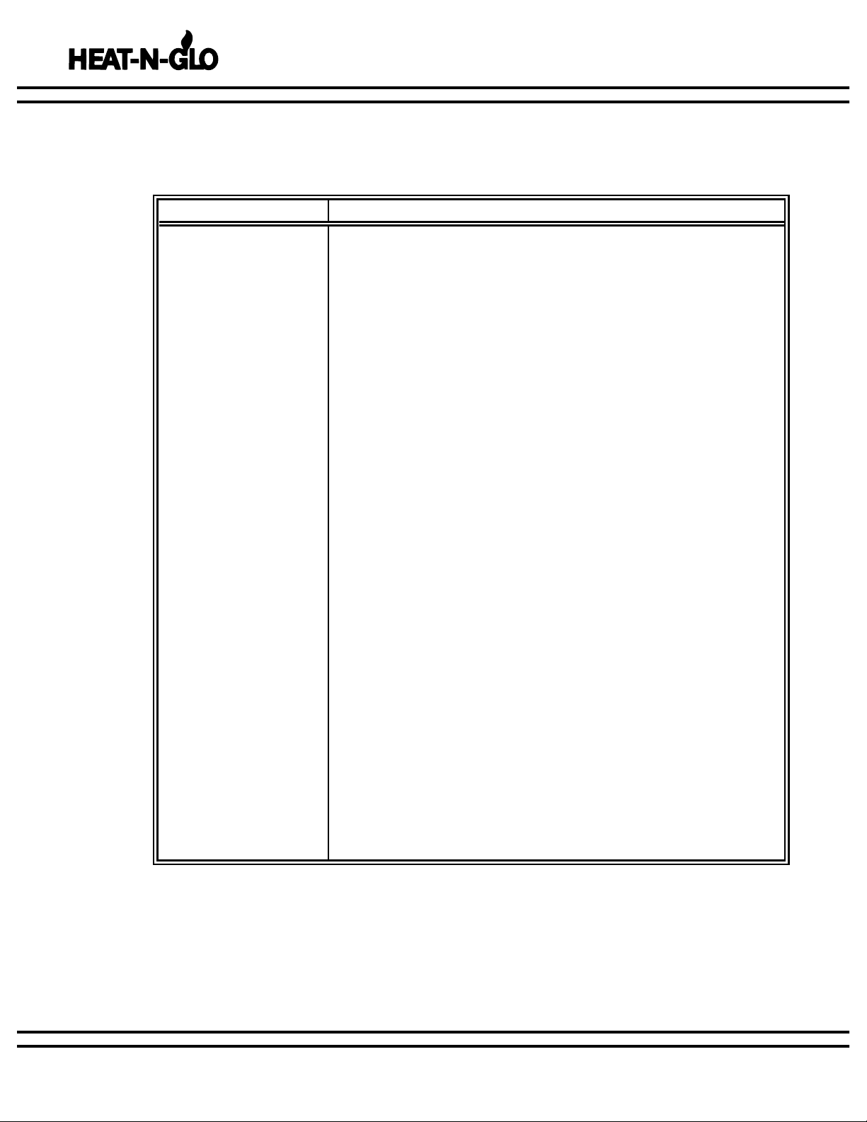
C. FIREPLACE SYSTEM COMPONENTS
No one builds a better fire
*Heat-N-Glo Part Number
The table below, together with the following pictures, show only those components which may be safely used
with this fireplace.
No one builds a better fire
175/8"
9
3
/8"
4"
36"
111/2"
5
/8"
33
5
/8"
21"
6"
7
1
/4"
10
7
/8"
21
7
/8"
18
3
/4"
385/8"
327/8"
8
"
1
"
71/4"
33/4"
36"
335/8"
21"
6"
38
5
/8"
327/8"
BW36
BW36C
52"
16"
4-00 5 30491D
GR16
AS8
HEARTH EXTENSIONS GLASS DOORS
OUTSIDE AIR KIT
STRAIGHT ATTIC
INSULATION SHIELD
INTEGRAL GRATES
BW36 SERIES WOODBURNING FIREPLACE
BI-FOLD DOORS
193/4"
351/2"
AK22
4"
42"
ID4
INSULATED DUCT
4"
42"
UD4
UNINSULATED DUCT
24"
DM1036
HX3
HTI CAT.# A
SL315 15°
SL330 30°
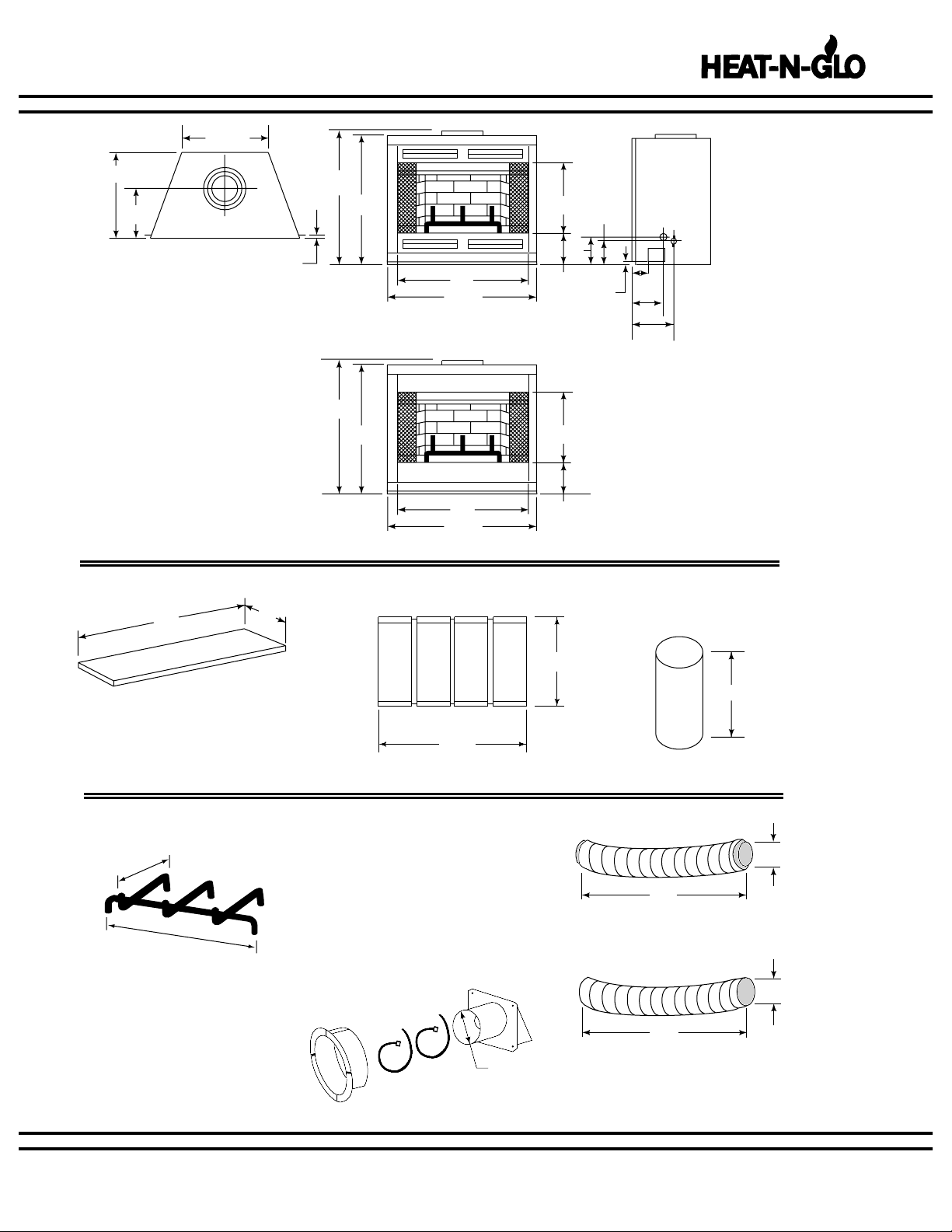
HTI CAT.# A B
SL306 6" 43/4"
SL312 12" 103/4"
SL318 18" 163/4"
SL324 24" 223/4"
SL336 36" 343/4"
SL348 48" 463/4"
HTI CAT.# A B
FS338 0° 141/2"
FS339 15° 183/8"
FS340 30° 23"
CHIMNEY SECTIONS CHIMNEY STABILIZER OFFSETS/RETURNS
SL3
FIRESTOP SPACERS ROOF FLASHING
101/2"
Flat to 6/12 Pitch
RF370
6/12 to 12/12 Pitch
RF371
4-00 6 30491D
BW36 SERIES WOODBURNING FIREPLACE
A= Actual length
B= Effective length (length of chimney part
after it has been snapped to another)
JB877
JOINT BAND
CHIMNEY BRACKET
CB876
No one builds a better fire
A
8"
A
8" 101/2"
203/4"
21"
6"
101/2"
101/2"
8"
A
B
141/2"
12"
271/4"
245/8"
12"
245/8"
271/4"
101/2"
2"
23"
143/4"
167/8"
153/4"
167/8"
291/4"
4-00 7 30491D
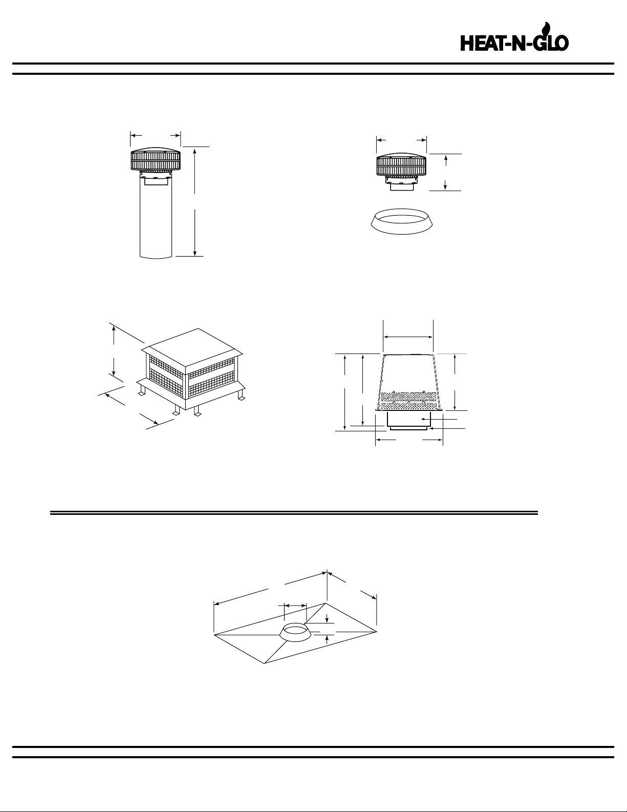
CHIMNEY TERMINAL CAPS & VENT SECTIONS
TR342
ROUND TERMINAL CAP
TR344
ROUND TERMINAL CAP
WITH STORM COLLAR
CT35
CHASE TOP
ST375
SQUARE TERMINAL CAP
72" 36"
2"
107/8"
BW36 SERIES WOODBURNING FIREPLACE
No one builds a better fire
(8" Flue)
(10
1
/2" Outer)
131/4"
231/2"
22
1
/4"
17
3
/4"
16
1
/2"
TS345/TS345P
SQUARE TERMINAL CAP
WITH OUTSIDE AIR
WITH OR WITHOUT OUTSIDE AIR
WITHOUT OUTSIDE AIR
4-00 8 30491D
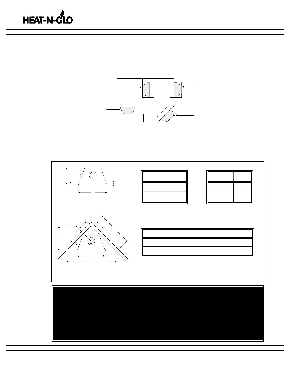
Figure 1
Fireplace Locations
Figure 2
Installation along a wall or an
exterior chase.
Figure 3
Corner Installation
BW36 SERIES WOODBURNING FIREPLACE
* A minimum of 1" air clearance must be
maintained between the firebox and wall.
1. FIREPLACE LOCATIONS AND SPACE REQUIREMENTS.
D. PRE-INSTALLATION PREPARATION
As a room divider.
Along a wall.
In an exterior chase or
projecting into a garage.
Across a corner.
WARNING!
DO NOT DRAW OUTSIDE AIR FROM GARAGE SPACES. EXHAUST PRODUCTS OF
GASOLINE ENGINES ARE HAZARDOUS.
DO NOT INSTALL OUTSIDE AIR DUCTS SUCH THAT THE AIR MAY BE DRAWN
FROM ATTIC SPACES, BASEMENTS OR ABOVE THE ROOF WHERE OTHER
HEATING APPLIANCES OR FANS AND CHIMNEYS EXHAUST OR UTILIZE AIR.
THESE PRECAUTIONS WILL REDUCE THE POSSIBILITY FOR SMOKING OR FLOW
REVERSAL.
CAT. # A B C D E
BW36 395/8” 621/4” 31” 137/8” 44”
BW36C 395/8” 621/4” 31” 137/8” 44”
CAT. # A
BW36 395/8"
BW36C 395/8"
No one builds a better fire
CAT. # A
BW36 395/8"
BW36C 395/8"
Several options are available to you when choosing a location for your fireplace. This fireplace may be used as
a room divider, installed along a wall, across a corner or use an exterior chase. See Figure 1.
Figures 2 and 3 show two typical installations assuming an outside air kit is being used. Therefore, an
allowance must be made for 90° bends. Less space is required when ducting goes directly outside without forming elbows.
3
/4"
19
A
C
D
D
E
A
B
 Loading...