

Heat & Glo LifeStyle BAY-40 User Manual
¨
Models:
BAY-40, PIER-40
Multi-sided
Woodburning Fireplace
Owner’s Manual
Installation and Operation
DO NOT DISCARD THIS MANUAL
• Important operating
and maintenance
instructions included.
• Read, understand
and follow these
instructions for safe
installation and
operation.
WARNING
If the information in these instructions is not followed exactly, a
fi re may result causing property
damage, personal injury, or death.
• Do not store or use gasoline or other fl am-
mable vapors and liquids in the vicinity of
this or any other appliance.
• Do not overfi re. Overfi ring will void your
warranty.
• Comply with all minimum clearances to
combustibles as specifi ed. Failure to
comply may cause house fi re.
CAUTION
¨
DO NOT
DISCARD
• Leave this manual with
party responsible for
use and operation.
WARNING
HOT SURFACES!
Glass and other surfaces are
hot during operation AND
cool down.
Hot glass will cause burns.
• Do not touch glass until it is cooled
• NEVER allow children to touch glass
• Keep children away
• CAREFULLY SUPERVISE children in same room
as fi replace.
• Alert children and adults to hazards of high
temperatures.
High temperatures may ignite clothing or other
fl ammable materials.
• Keep clothing, furniture, draperies and other
fl ammable materials away.
Installation and service of this fi replace should
be performed by qualifi ed personnel. Hearth &
Home Technologies suggests NFI certifi ed or
factory-trained professionals, or technicians
supervised by an NFI certified
professional.
Heat & Glo • Multi-Sided Woodburning Fireplace • 34977 Rev T • 11/07
WARNING
Fire Risk
• For use with solid wood fuel or decorative
gas appliance only.
• Do not install unvented gas logs.
1
Read this manual before installing or operating this fi replace.
Please retain this owner’s manual for future reference.
Congratulations!
Congratulations on selecting a Heat & Glo wood burning fi re-
place. The Heat & Glo fi replace you have selected is designed
to provide the utmost in safety, reliability and effi ciency.
As the owner of a new fi replace, you’ll want to read and care-
fully follow all of the instructions contained in this owner’s
manual. Pay special attention to all cautions and warnings.
This owner’s manual should be retained for future reference.
We suggest you keep it with your other important documents
and product manuals.
The information contained in this owner’s manual unless noted
otherwise, applies to all models and gas control systems.
Your new Heat & Glo wood burning fi replace will give you
years of durable use and trouble-free enjoyment. Welcome
to the Heat & Glo family of fi replace products!
Homeowner Reference Information
We recommend that you record the following pertinent
information about your fi replace:
Model Name: Date purchased/installed:
Serial Number: Location on fi replace:
Dealership purchased from: Dealer phone:
Notes:
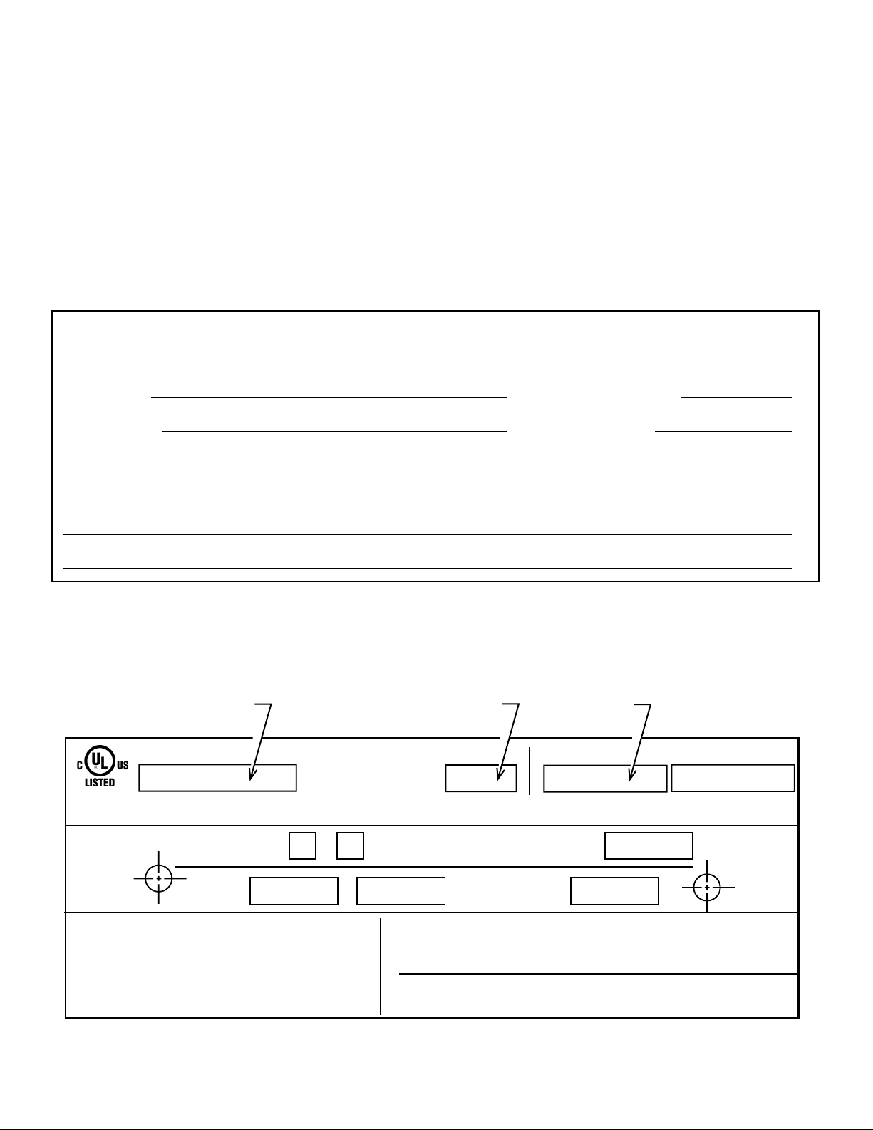
Listing Label Information/Location
The model information regarding your specifi c fi replace can be found on the rating plate located on the smoke shield of the
fi replace.
Serial
Number
Grate
Fireplace
Model
FIREPLACE NO.
FIRECHAMBER INTENDED FOR USE WITH HEARTH & HOME TECHNOLOGIES INC. LISTED FIREPLACE PARTS. SEE INSTALLATION AND
OPERATING INSTRUCTIONS FOR THIS MODEL. ONLY HEARTH & HOME TECHNOLOGIES INC. GLASS DOOR KITS CAN BE INSTALLED ON THIS UNIT.
FIREPLACE ALSO FOR USE
IN MANUFACTURED HOMES
FAN KI T
MODEL NO.
DO NOT OVERFIRE. USE ONLY: SOLID WOOD FUEL OR
LISTED DECORATIVE GAS APPLIANCE. DO NOT USE A
FIREPLACE INSERT OR OTHER PRODUCTS NOT
SPECIFIED FOR USE WITH THIS PRODUCT. IF DOORS
ARE USED OPERATE FIREPLACE WITH DOORS FULLY
OPEN OR CLOSED ONLY. WHEN BURNING A
DECORATIVE GAS APPLIANCE IN THE FIREPLACE,
ADJUST DAMPER TO THE FULLY OPEN POSITION.
2
Heat & Glo • Multi-Sided Woodburning Fireplace • 34977 Rev T • 11/07
YES
WARNING: RISK OF
FIRE DAMAGE. REPLACE
GRATE WITH HEARTH & HOME
TECHNOLOGIES INC.
NO
&
MODEL NO.
CLEARANCE TO
COMBUSTIBLES:
WARNING! THIS FIREPLACE HAS NOT BEEN TESTED WITH AN UNVENTED
GAS LOG SET. TO REDUCE THE RISK OF FIRE OR INJURY, DO NOT
INSTALL AN UNVENTED GAS LOG SET INTO FIREPLACE.
WARNING! THIS APPLIANCE IS NOT FOR USE AS COOKING EQUIPMENT.
IF INSTALLATION OR OPERATING INSTRUCTIONS ARE MISSING
CONTACT: HEARTH & HOME TECHNOLOGIES INC.,
1915 W. SAUNDERS ST., MT. PLEASANT, IA 52641.
CHIMNEY
2 IN. MIN.
RATED AT
115 VOLTS, 50/60 Hz.,
MODEL NO.
FIREBOX
MFG. DATE
IN.
MIN.
AMP.

Table of Contents
1 Listing and Code Approvals 4
A. Appliance Certifi cation . . . . . . . . . . . . . . . . . . . . . . . . . 4
2 Getting Started 5
A. Design and Installation Considerations . . . . . . . . . . . . 5
B. Negative Pressure . . . . . . . . . . . . . . . . . . . . . . . . . . . .5
C. Typical Fireplace System . . . . . . . . . . . . . . . . . . . . . . . 7
D. Tools and Supplies Needed . . . . . . . . . . . . . . . . . . . . . 8
E. Inspect Fireplace and Components . . . . . . . . . . . . . . . 8
3 Framing and Clearances 9
A. Selecting Fireplace Location . . . . . . . . . . . . . . . . . . . . 9
B. Clearances . . . . . . . . . . . . . . . . . . . . . . . . . . . . . . . . . 10
C. Sidewalls/Surrounds . . . . . . . . . . . . . . . . . . . . . . . . . 11
E. Construct the Chase . . . . . . . . . . . . . . . . . . . . . . . . . 12
F. Chimney Requirements . . . . . . . . . . . . . . . . . . . . . . . 12
4 Installation of Fireplace 13
A. Install the Outside Air Kit . . . . . . . . . . . . . . . . . . . . . . 13
5 Chimney Assembly 16
A. Chimney Requirements . . . . . . . . . . . . . . . . . . . . . . .17
B. Using Offsets/Returns . . . . . . . . . . . . . . . . . . . . . . . . 18
C. Assemble the Chimney Sections . . . . . . . . . . . . . . . .19
D. Install the Ceiling Firestops . . . . . . . . . . . . . . . . . . . . 19
E. Install the Attic Insulation Shield . . . . . . . . . . . . . . . . 20
F. Double-check the Chimney Assembly . . . . . . . . . . . .21
G. Secure the Chimney . . . . . . . . . . . . . . . . . . . . . . . . .21
6 Complete the Enclosure 22
A. Chimney Termination . . . . . . . . . . . . . . . . . . . . . . . . . 22
B. Chase Top . . . . . . . . . . . . . . . . . . . . . . . . . . . . . . . . . 24
C. Install the Termination Cap . . . . . . . . . . . . . . . . . . . . 24
7 Accessories 26
A. Gas Log/Lighter Provisions . . . . . . . . . . . . . . . . . . . . 26
8 Finishing 27
A. Hearth Extension . . . . . . . . . . . . . . . . . . . . . . . . . . . .27
B. Finishing Material . . . . . . . . . . . . . . . . . . . . . . . . . . . . 28
C. Mantel . . . . . . . . . . . . . . . . . . . . . . . . . . . . . . . . . . . .29
D. Sidewalls/Surrounds . . . . . . . . . . . . . . . . . . . . . . . . .29
E. Glass Doors . . . . . . . . . . . . . . . . . . . . . . . . . . . . . . . . 29
9 Operating Instructions 30
A. General Information . . . . . . . . . . . . . . . . . . . . . . . . . . 30
B. Outside Air . . . . . . . . . . . . . . . . . . . . . . . . . . . . . . . . . 31
C. Clear Space Near the Fireplace. . . . . . . . . . . . . . . . . 31
D. Flue Damper . . . . . . . . . . . . . . . . . . . . . . . . . . . . . . .31
E. Firescreen . . . . . . . . . . . . . . . . . . . . . . . . . . . . . . . . . 31
F. Glass Doors . . . . . . . . . . . . . . . . . . . . . . . . . . . . . . . . 31
G. Grate . . . . . . . . . . . . . . . . . . . . . . . . . . . . . . . . . . . . . 32
H. Wood Fuel . . . . . . . . . . . . . . . . . . . . . . . . . . . . . . . . . 32
I. Starting a Fire . . . . . . . . . . . . . . . . . . . . . . . . . . . . . . 33
10 Troubleshooting 34
A. Understanding Vent Problems . . . . . . . . . . . . . . . . . . 34
B. Diagnostics and Problem Solving . . . . . . . . . . . . . . . 35
11 Maintenance and Servicing the Fireplace 37
A. Disposal of Ashes . . . . . . . . . . . . . . . . . . . . . . . . . . . 37
B. Chimney Inspection/Cleaning . . . . . . . . . . . . . . . . . . 37
C. Firebox Refractory . . . . . . . . . . . . . . . . . . . . . . . . . . . 37
D. Maintenance Task List . . . . . . . . . . . . . . . . . . . . . . . . 38
E. Chimney Fire . . . . . . . . . . . . . . . . . . . . . . . . . . . . . . . 38
12 Reference Materials 39
A. Fireplace Dimensions . . . . . . . . . . . . . . . . . . . . . . . .39
B. Fireplace Components . . . . . . . . . . . . . . . . . . . . . . . . 40
C. Chimney Components . . . . . . . . . . . . . . . . . . . . . . . . 41
D. Service Parts . . . . . . . . . . . . . . . . . . . . . . . . . . . . . . . 46
E. Limited Warranty . . . . . . . . . . . . . . . . . . . . . . . . . . . . 51
F. Contact Information . . . . . . . . . . . . . . . . . . . . . . . . . . 52
Note: An arrow (¨) found in the text signifi es change in content.
Heat & Glo • Multi-Sided Woodburning Fireplace • 34977 Rev T • 11/07
3
1
Listing and Code Approvals
1
A. Appliance Certifi cation
This fi replace system has been tested and listed in accor-
dance with UL 127 standards by Underwriters Laboratories
Inc. for installation and operation in the United States.
This fi replace has been tested and listed for use with the
optional components specifi ed in this manual. Glass doors
are required. Optional components may be purchased separately and installed at a later date. Installation of an outside
air kit will require signifi cant reconstruction and is best if in-
stalled at the time of fi replace installation.
Heat & Glo is a registered trademark of Hearth & Home
Technologies Inc.
WARNING
Fire Risk
WARNING
Improper installation, adjustment, alteration, service
or maintenance can cause injury or property damage.
Refer to the owner’s information manual provided with
this fi replace. For assistance or additional information
consult a qualifi ed installer, service agency or your
dealer.
Not intended for use as a primary heat source.
This fi replace is tested and approved as a decorative fi re-
place. It should not be factored as a primary heat source
in residential heating calculations.
• Do not install or operate damaged fi replace.
• Do not modify fi replace.
• Installation other than as instructed by Hearth & Home
Technologies Inc. is strictly prohibited.
• Do not operate the fi replace without fully assembling
all components.
• Do not overfi re.
• Do not install an unvented gas log set. This fi replace
has not been tested for use with unvented gas log
sets.
• Installation and/or use of any component part not
approved by Hearth & Home Technologies.
Hearth & Home Technologies disclaims any responsibility
for, and the warranty and agency listing will be voided by
the above actions.
4
Heat & Glo • Multi-Sided Woodburning Fireplace • 34977 Rev T • 11/07
2
Getting Started
2
A. Design and Installation Considerations
CAUTION
Check building codes prior to installation.
• Installation MUST comply with local, regional,
state and national codes and regulations.
• Consult insurance carrier, local building inspector,
fi re offi cials or authorities having jurisdiction about
restrictions, installation inspection and permits.
When planning a fi replace installation, it is necessary to de-
termine the following information before installing:
• Where the fireplace is to be installed. See Sections
3 and 4.
• The vent system confi guration to be used. See Sections
5 and 6.
• Gas supply piping. See Section 7.
• Electrical wiring. See Section 7.
• Framing and fi nishing details. See Sections 3, 6 and 8.
• Whether optional accessories—devices such as a fan, wall
switch or remote control —are desired. See Section 12.
Draft is the pressure difference needed to vent fi replaces
successfully. Considerations for successful draft include:
• Preventing negative pressure
• Location of fi replace and chimney
WARNING
Asphyxiation Risk
Negative pressure can cause spillage of
combustion fumes and soot. Fire needs to draft
properly for safe operation.
B. Negative Pressure
Negative pressure results from the imbalance of air available for the fi replace to operate properly. Causes for this
imbalance include:
• Exhaust fans (kitchen, bath, etc.).
• Range hoods.
• Combustion air requirements for furnaces, water heaters
and other combustion appliances.
• Clothes dryers.
• Location of return-air vents to furnace or air
conditioning.
• Imbalances of the HVAC air handling system.
• Upper level air leaks: recessed lighting, attic hatch
opening, duct leaks.
To minimize the effects of negative air pressure, the following must be considered:
• Install the outside air kit. Install the intake on the side of
the house towards prevailing winds during the heating
season.
• Ensure adequate outdoor air is supplied for combustion
appliances and exhaust equipment.
• Ensure furnace and air conditioning return vents are not
located in the immediate vicinity of the fi replace.
• Avoid installing the fi replace near doors, walkways or small
isolated spaces.
• Recessed lighting should be a “sealed can” design; attic
hatches weather stripped or sealed; attic mounted duct
work and air handler joints and seams taped or sealed.
• Basement installations should be avoided due to stack
effect. Stack effect creates negative pressure in lower
levels. Hearth & Home Technologies recommends the
use of direct vent fi replaces in basements.
Heat & Glo • Multi-Sided Woodburning Fireplace • 34977 Rev T • 11/07
5
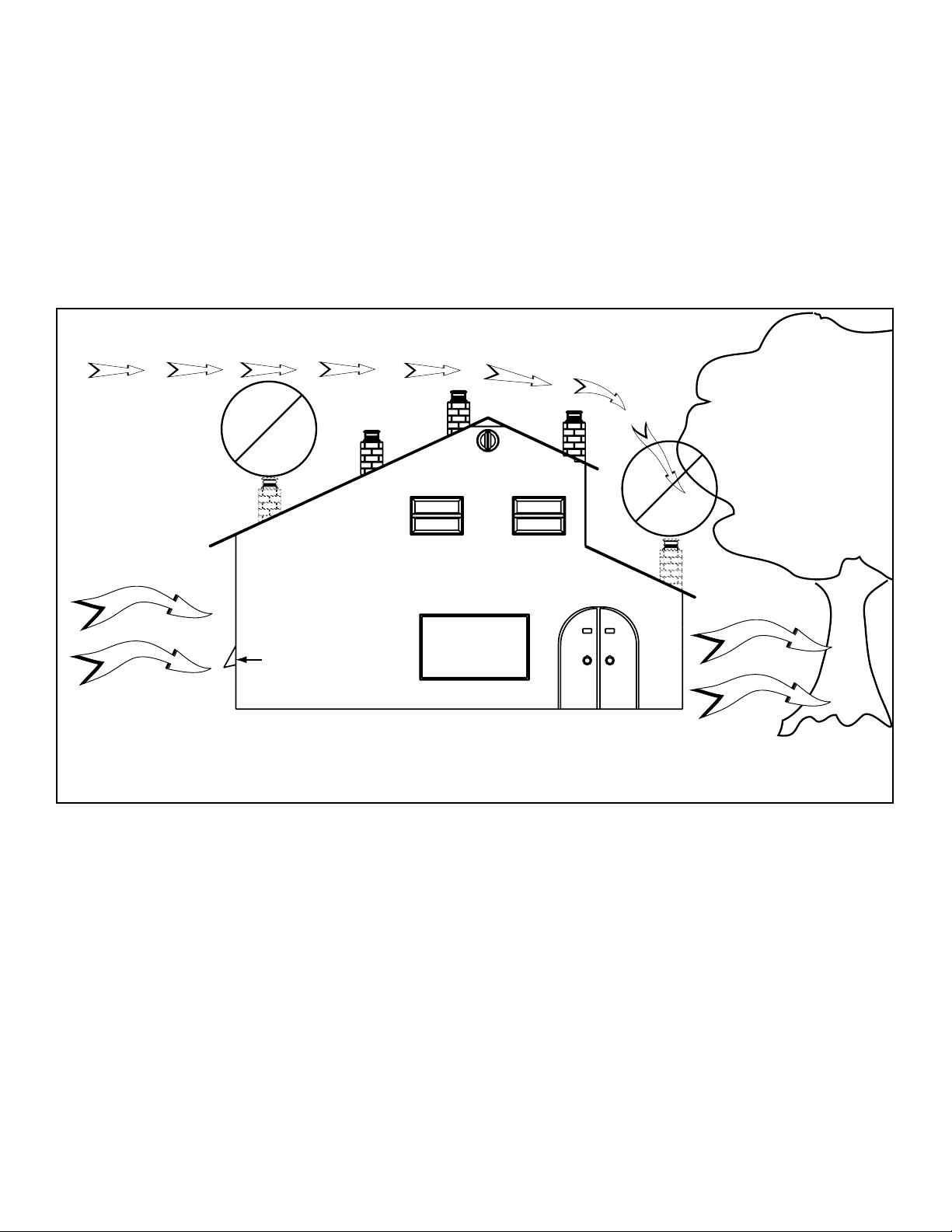
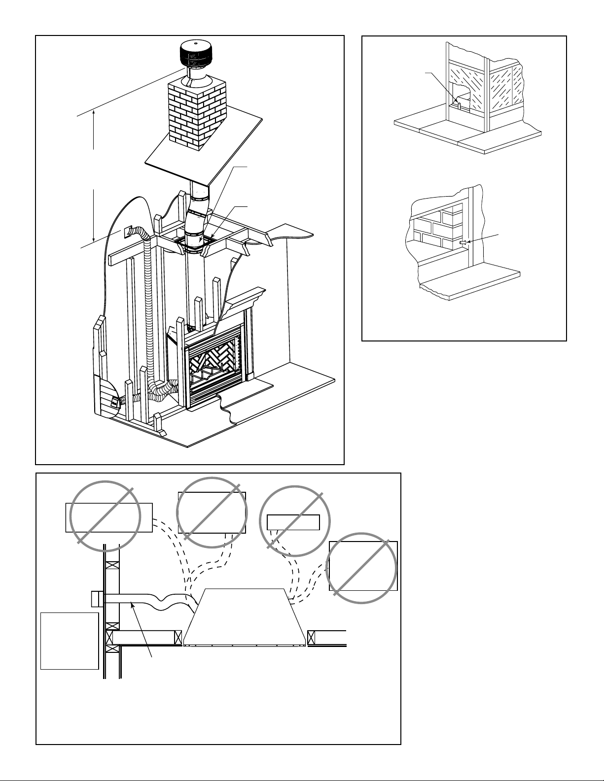
Location of the fi replace and chimney will affect performance.
As shown in Figure 2.1 the chimney should:
• Be installed through the warm airspace enclosed by the
building envelope. This helps to produce more draft,
especially during lighting and die-down of the fi re.
• Penetrate the highest part of the roof. This minimizes the
effects of wind turbulence.
• Be located away from trees, adjacent structures, uneven
roof lines and other obstructions.
Offsets can restrict draft so their use should be minimized.
Consider the fi replace location relative to fl oor and ceiling
and attic joists.
Windward
Location
Not
Recommended
Outside Air Intake
Marginal
Location
Recommended
Location
Multi-level Roofs
Recommended
Location
Location
Not
Recommended
Leeward
Figure 2.1 Recommended Chimney Locations
6
Heat & Glo • Multi-Sided Woodburning Fireplace • 34977 Rev T • 11/07
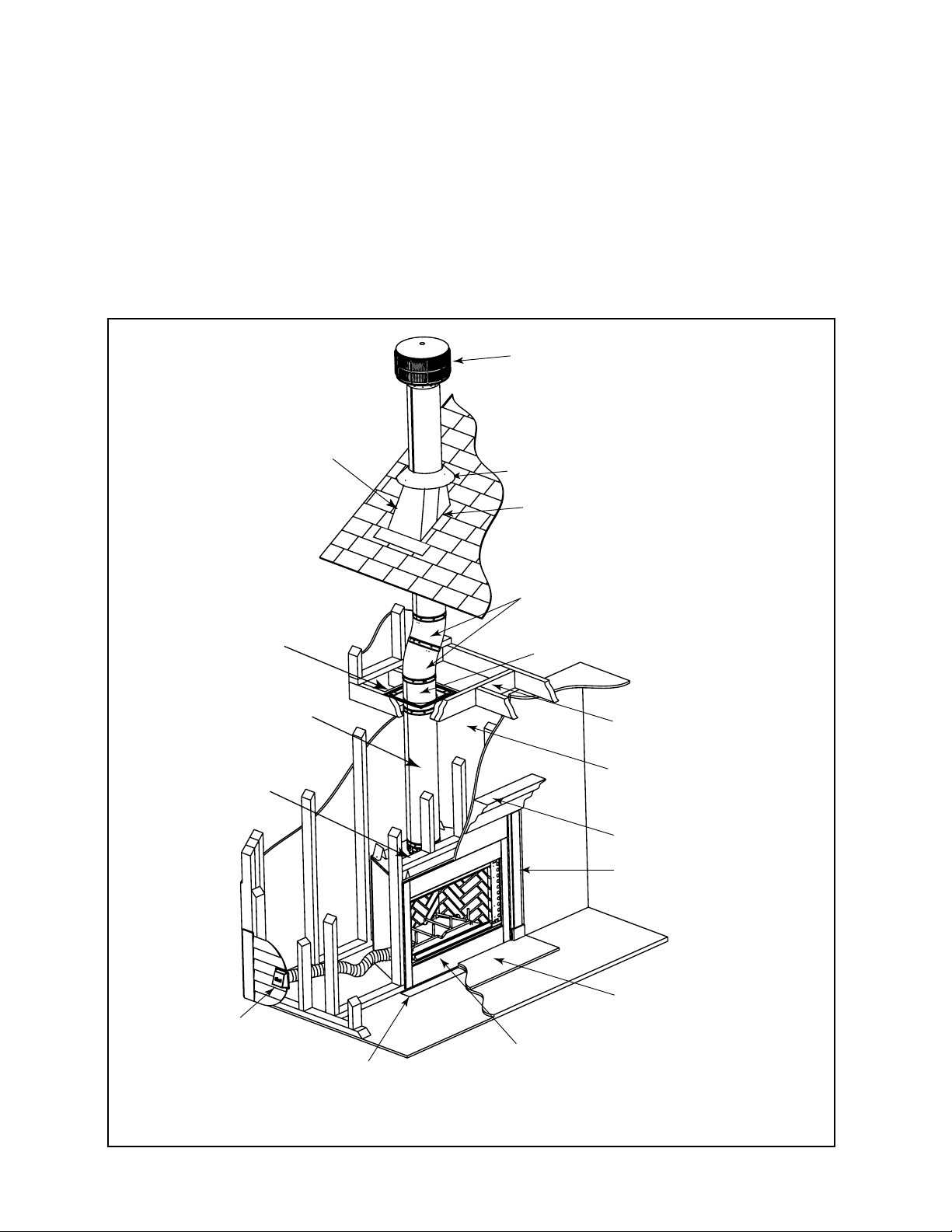
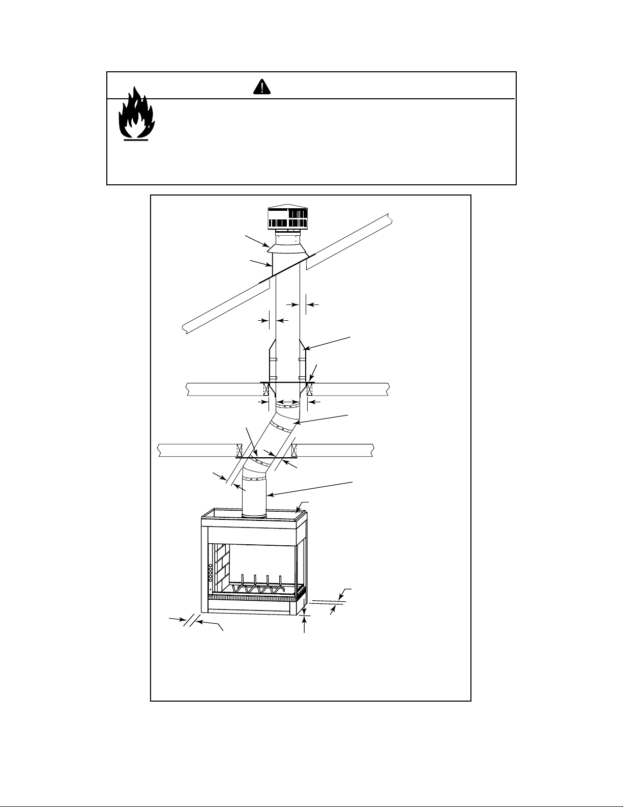
C. Typical Fireplace System
The Heat & Glo fi replace system consists of the following:
• Fireplace/integral grate/refractory/outside air system
• Refractory
• Chimney termination cap
• Chimney system
• Hearth extension
• Glass Doors
Optional components include:
• Chimney air kit
Additional lateral
support for chimney
above roof (or enclosed
in chase) if needed
Non-combustible
roof flashing maintains
minimum clearance
around chimney
Support straps
on rafter supports
chimney (not shown)
Ceiling firestop
on floor of attic
Termination cap
Storm Collar
Chimney penetrates roof
preferably without affecting
roof rafters
Offset/Return (with hanger straps)
Attic insulation shield (not shown) must
be used here to keep insulation away
from chimney if attic is insulated
Chimney system
Combustible
framing/header
on top of
V-shaped
standoffs
(spacers)
Outside
combustion air
Protective metal
hearth strip(s)
Figure 2.2 Typical Fireplace System
Framing headed off
in ceiling joists
Enclosed space above
and around fireplace
Mantel and surround
Decorative facing
and trim
Hearth extension
Factory-built fireplace
Heat & Glo • Multi-Sided Woodburning Fireplace • 34977 Rev T • 11/07
7
D. Tools and Supplies Needed
E. Inspect Fireplace and Components
Before beginning the installation be sure the following tools
and building supplies are available:
Reciprocating saw Framing material
Pliers High temp caulking material
Hammer Gloves
Phillips screwdriver Framing square
Flat blade screwdriver Electric drill and bits
Plumb line Safety glasses
Level Tape measure
1/2-3/4 in. length, #6 or #8 self-drilling screws
Misc. screws and nails
CAUTION
• Keep fi replace dry.
• Mold or rust may cause odors.
WARNING
Fire Risk
Explosion Risk
Inspect fireplace and components for
damage. Damaged parts may impair safe
operation.
• Do NOT install damaged components.
• Do NOT install incomplete components.
• Do NOT install substitute components
Report damaged parts to dealer.
• Carefully remove the fi replace and components from the
packaging.
• The vent system components and doors are shipped in
separate packages.
• Report to your dealer any parts damaged in shipment.
• Read all the instructions before starting the installation.
Follow these instructions carefully during the
installation to ensure maximum safety and benefi t.
8
Heat & Glo • Multi-Sided Woodburning Fireplace • 34977 Rev T • 11/07
3
Framing and Clearances
3
WARNING
Fire Risk
Provide adequate clearances.
• Around air openings
• To combustibles
• For service access.
Locate fi replace away from traffi c areas.
A. Selecting Fireplace Location
Several options are available to you when choosing a location for your fi replace. This fi replace may be used as a room
divider, installed along a wall, across a corner or used in an
exterior chase. See Figure 3.1.
62 in.
(1575 mm)
16 in.
(406 mm)
72 in.
(1829 mm)
16 in.
(406 mm)
Note:
• Illustrations and photos refl ect typical installations
and are FOR DESIGN PURPOSES ONLY.
• Illustrations/diagrams are not drawn to scale.
• Actual installation/appearance may vary due to
individual design preference.
• Hearth & Home Technologies reserves the right to
alter its products.
Locating the fi replace in a basement, near frequently opened
doors, central heat outlets or returns, or other locations of
considerable air movement can affect the performance and
cause intermittent smoke spillage from the front of the fi re-
place. Consideration should be given to these factors before
deciding on a location. See Sections 2 and 10.
12 in. (305 mm)
from opening of
fireplace
Note:
1/2 in. min. distance from
fireplace to combustible
materials.
40-1/2 in.
(1029 mm)
HEARTH
EXTENSION
(shaded)
BAY-40 PIER-40
Figure 3.1 Fireplace Locations
(660 mm)
to front of
fireplace
opening
64 in.
(1626 mm)
26 in.
56 in.
(1422 mm)
EXTENSION
HEARTH
(shaded)
(152 mm)
64 in.
(1626 mm)
6 in.
In addition to these
Note:
framing dimensions,
also reference the
following sections:
• Clearances (Section
3.B.)
• Mantel Projections
(Section 8.C)
• Fireplace Dimensions
(Section 12.A.)
Heat & Glo • Multi-Sided Woodburning Fireplace • 34977 Rev T • 11/07
9
B. Clearances
WARNING
Fire Risk
• Comply with all minimum clearances to combustibles as specifi ed.
• Framing or fi nishing material used on the front of, or in front of, the
appliance closer than the minimums listed, must be constructed entirely
of noncombustible materials (i.e., steel studs, concrete board, etc.).
Failure to comply may cause fi re.
Storm Collar
Roof Flashing
2 in. min.
(51 mm)
(attic)
(roof)
2 in. (51 mm) min.
Attic
Insulation
Shield
Ceiling Firestop
2 in. (51 mm) min.
Ceiling Firestop
2 in. (51 mm) min.
1/2 in. (13 mm) to
side of appliance
(ceiling)
2 in. (51 mm) min.
2 in. (51 mm) min.
(ceiling)
2 in. (51 mm) min.
0 in. to level
of standoffs
1/2
0 in.
to floor
Offset/Return with
hanger straps
Must have 2 in. (51 mm)
minimum clearance
to header
in. [13 mm] to back
of appliance
10
Figure 3.2 Clearances to Combustible Materials
Heat & Glo • Multi-Sided Woodburning Fireplace • 34977 Rev T • 11/07
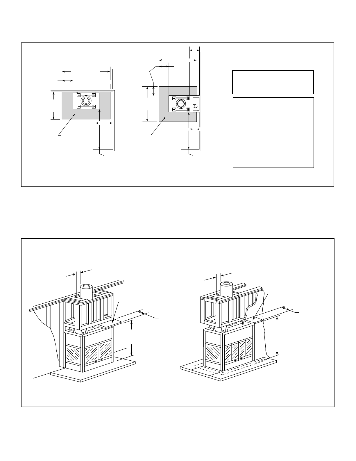
C. Sidewalls/Surrounds
Adjacent combustible side walls must be located a minimum distance from the fi replace opening as per Figure 3.3.
12 in. (305 mm)
from opening of
fireplace
(152 mm)
64 in.
(1626 mm)
6 in.
Note:
1/2 in. min. distance from
fireplace to combustible
materials.
In addition to these
Note:
framing dimensions,
also reference the
following sections:
• Clearances (Section
3.B.)
• Mantel Projections
(Section 8.C)
• Fireplace Dimensions
(Section 12.A.)
72 in.
(1829 mm)
16 in.
(406 mm)
40-1/2 in.
(1029 mm)
HEARTH
EXTENSION
(shaded)
BAY-40 PIER-40
Figure 3.3 Sidewalls and Surrounds
(1626 mm)
64 in.
16 in.
(406 mm)
(1422 mm)
26 in.
(660 mm)
to front of
fireplace
opening
62 in.
(1575 mm)
56 in.
HEARTH
EXTENSION
(shaded)
D. Frame the Fireplace
Figure 3.4 shows a typical framing (using 2 x 4 lumber) of the fi replace, assuming combustible materials are used. All re-
quired clearances to combustibles around the fi replace must be adhered to. See Figure 3.2. Any framing across the top of
the fi replace must be above the level of the top standoffs.
2 in. (51 mm) minimum air space
clearance to enclosure
Figure 3.4 Framing the Fireplace
Mantel
47-1/8 in. (1197 mm)
Header Height
BAY-40
12 in. max.
(305 mm)
2 in. (51 mm) minimum air space
clearance to enclosure
Mantel
12 in. max.
(305 mm)
47-1/8 in. (1197 mm)
Header Height
PIER-40
Heat & Glo • Multi-Sided Woodburning Fireplace • 34977 Rev T • 11/07
11
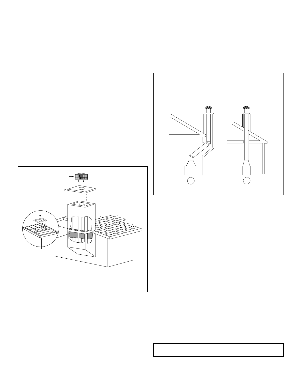
E. Construct the Chase
A chase is a vertical boxlike structure built to enclose the fi re-
place and/or its vent system. Vertical chimneys that run on
the outside of a building must be installed inside a chase.
Construction of the chase may vary with the type of building. These instructions are not substitutes for the requirements of local building codes. Local building codes MUST
be checked.
Chases should be constructed in the manner of all outside
walls of the home to prevent cold air drafting problems. The
chase should not break the outside building envelope in any
manner. All outer walls need to be insulated.
Building codes require false ceiling and ceiling fi restops at
each fl oor of the chase or every 10 ft (3.05 m) of clear space
to control spread of fi re.
Walls, ceiling, base plate and cantilever fl oor at the fi rst level
of the chase should be insulated. See Figure 3.5. Vapor and
air infi ltration barriers should be installed in the chase as per
regional codes for the rest of the home. Additionally, Hearth
& Home Technologies recommends that the inside surfaces be sheet rocked and taped (or the use of an equivalent
method) for maximum air tightness.
Gas line holes and other openings should be caulked with
high temperature caulk or stuffed with unfaced fi berglass in-
sulation. If the fi replace is being installed on a cement slab,
we recommend that in cold climates, a sheet of plywood or
other raised platform be placed underneath to prevent conducting cold up into the room.
Three examples of chase applications are shown in Figure 3.6.
1. Fireplace and chimney enclosed in an exterior chase.
2. Chimney offset through exterior wall and enclosed in
chase.
3. Chase constructed on roof.
Round Termination Cap
Metal Chase Top
Ceiling
Firestop
False Ceiling
Figure 3.5 Chase Assembly
1
Figure 3.6 Chase Constructions
2
F. Chimney Requirements
When planning your fi replace location, the chimney con-
struction and necessary clearances must be considered.
The fi replace system and chimney components have been
tested to provide fl exibility in construction. Vertical distances
are measured from the base of the fi replace as shown in
Figure 5.2.
• Minimum overall straight height 14 (4.27 m)
• Minimum height with offset/return 16.5 ft (5.03 m)
• Maximum height 90 ft (27.43 m)
• Maximum chimney length between an offset
and return
• Maximum distance between chimney
stabilizers
• Double offset/return minimum height 20 ft (6.1 m)
• Maximum unsupported chimney length
between the offset and return
• Maximum unsupported chimney height above
the fi replace
• Maximum unsupported chimney above roof 6 ft (1.83 m)
20 ft (6.1 m)
35 ft (10.67 m)
6 ft (1.83 m)
35 ft (10.67 m)
12
Note: A maximum of two pairs of offsets and returns may
be used.
Heat & Glo • Multi-Sided Woodburning Fireplace • 34977 Rev T • 11/07
4
Installation of Fireplace
4
CAUTION
Sharp Edges
• Wear protective gloves and safety glasses
during installation.
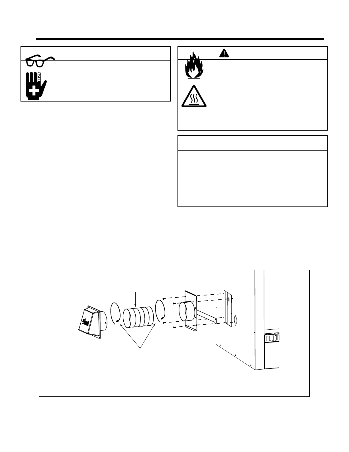
A. Install the Outside Air Kit
This fi replace will operate correctly only if adequate ventila-
tion is provided to allow proper draft to the fi replace system.
See Section 2.
The outside air kit is supplied with this fi replace. Using an
outside air kit is highly recommended to minimize the effects
of negative pressure within the structure. We recommend
you utilize the shortest duct run to optimize the performance
of the outside air kit. Cold air fl ow can be minimized by put-
ting a small dip in the duct creating a cold air trap. This trap
can also help prevent heat build-up and exhausting out the
intake due to the stack effect. The outside air kit inlet should
be positioned in a manner that will not allow snow, leaves,
etc. to block the inlet. In some installations the air duct
may need to be run vertically. In such an installation, a 3 ft
(.914 m) height difference must be maintained from the top
of the uppermost chimney section to the outside combustion
air inlet. See Figure 4.2.
See Figure 4.3 for proper placement of outside air inlet.
WARNING
Fire Risk
Asphyxiation Risk
Do not draw outside combustion air from:
• Wall, fl oor or ceiling cavity.
• Enclosed space such as an attic or
garage.
• Close proximity to exhaust vents or
chimneys.
Fumes or odor may result.
CAUTION
Risk of Smoke Spillage
Outside air inlet must be located to prevent blockage
from:
• Leaves
• Snow/ice
• Other debris
Blockage may cause combustion air starvation.
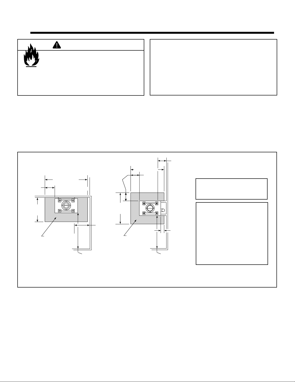
The outside air kit is installed on the right side (PIER-40)
or open end (BAY-40) of the fi replace. See Figure 4.4 for
handle location/operation.
Remove the cover plate from the side (PIER-40) or bottom
(BAY-40) of the fi replace assembly where the air kit is to be
installed.
Outside Air
Shield
Figure 4.1 Outside Air Installation
Heat & Glo • Multi-Sided Woodburning Fireplace • 34977 Rev T • 11/07
Flexible Duct
(not supplied)
2 Wire Ties
Outside Air
Plate
Assembly
13
3 ft min. from top of
uppermost chimney
section to air inlet.
Attic insulation shield
must be used to keep
insulation away from
chimney.
Ceiling firestop
on floor of attic.
LIFT TO
OPEN
BAY-40
PULL TO
OPEN
PIER-40
Figure 4.4 Locating the Outside Air Control
Figure 4.2 Outside Air Inlet Locations
NO
NO
Outlet blocked by
snow, leaves, etc.
Garage or
combustible
liquids storage
YES
Clear area
outside
house or in
ventilated
crawl space
Use only duct materials specified
by manufacturer (preferably with
short run or mainly straight duct,
except small dip for cold air trap
which will help prevent flow of cold air).
Figure 4.3 Outside Combustion Air Placement
NO
Attic space
NO
Outlet placed
higher than 3 ft
below the
termination cap
Factory-built
fireplace
14
Heat & Glo • Multi-Sided Woodburning Fireplace • 34977 Rev T • 11/07
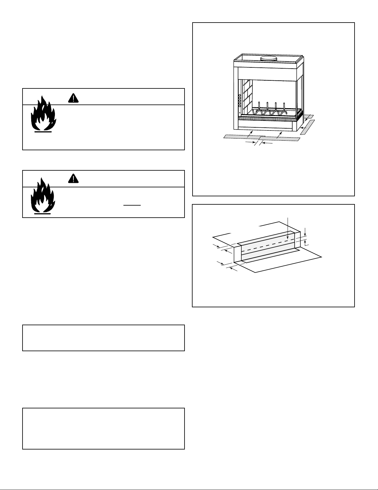
B. Secure the Fireplace
• Position the Fireplace
This fi replace may be placed on either a combustible or
noncombustible continuous fl at surface. Follow the in-
structions for framing in Section 3.D. Slide the fi replace
into position. Be sure to provide the minimum air clearance at the sides and back of the fi replace assembly.
See Section 3.B.
WARNING
Fire Risk!
• Prevent contact with sagging, loose
insulation.
• Do NOT install against vapor barriers or
exposed insulation.
• Place the Protective Metal Hearth Strips
WARNING
Fire Risk!
• Metal hearth strips MUST be installed.
Sparks or embers may ignite fl ooring.
1 in. (25 mm)
overlap
Metal strips 2 in. (51 mm) under the edges
of the fireplace and must extend beyond the
front and side openings by 2 in. (51 mm)
Figure 4.5 Position the Protective Metal Hearth Strips
Top piece must overlap
bottom piece
Included with your fi replace you will fi nd two metal
hearth strips measuring approximately 26 in. x 4 in.
(660 mm x 102 mm). These strips are used to provide
added protection where the fi replace and the hearth ex-
tension meet.
Slide each metal strip 2 in. (51 mm) under the front
edge of the fi replace. The individual pieces must over-
lap each other by 1 in. (25 mm) minimum in the middle
of the fi replace to provide continuous coverage of the
fl oor. See Figure 4.5. These metal strips should extend
from the front and sides of the fi replace opening by 2 in.
(51 mm).
Note: When elevating the fi replace above the hearth exten-
sion the front of the elevated platform must be protected with
a protective metal hearth strip as shown in Figure 4.6.
• Level the Fireplace
Level the fi replace side-to-side and front-to-back. Shim
with noncombustible material, such as sheet metal, as
necessary. Secure the fi replace (using the nailing fl ang-
es located on either side of the fi replace) to the vertical
framing.
Raised Platform
2 in.
(51 mm)
Floor
2 in.
(51 mm)
Figure 4.6 Protect the Front of an Elevated Platform
1 in. (25 mm) min.
overlap
Important: To e n s u r e p r op e r fi t of the glass doors, check
the fi replace opening for square. Measure diagonal dis-
tances of the opening to make sure they are equal. If they
are not, continue to shim the fi replace until those diagonals
are equal.
Heat & Glo • Multi-Sided Woodburning Fireplace • 34977 Rev T • 11/07
15
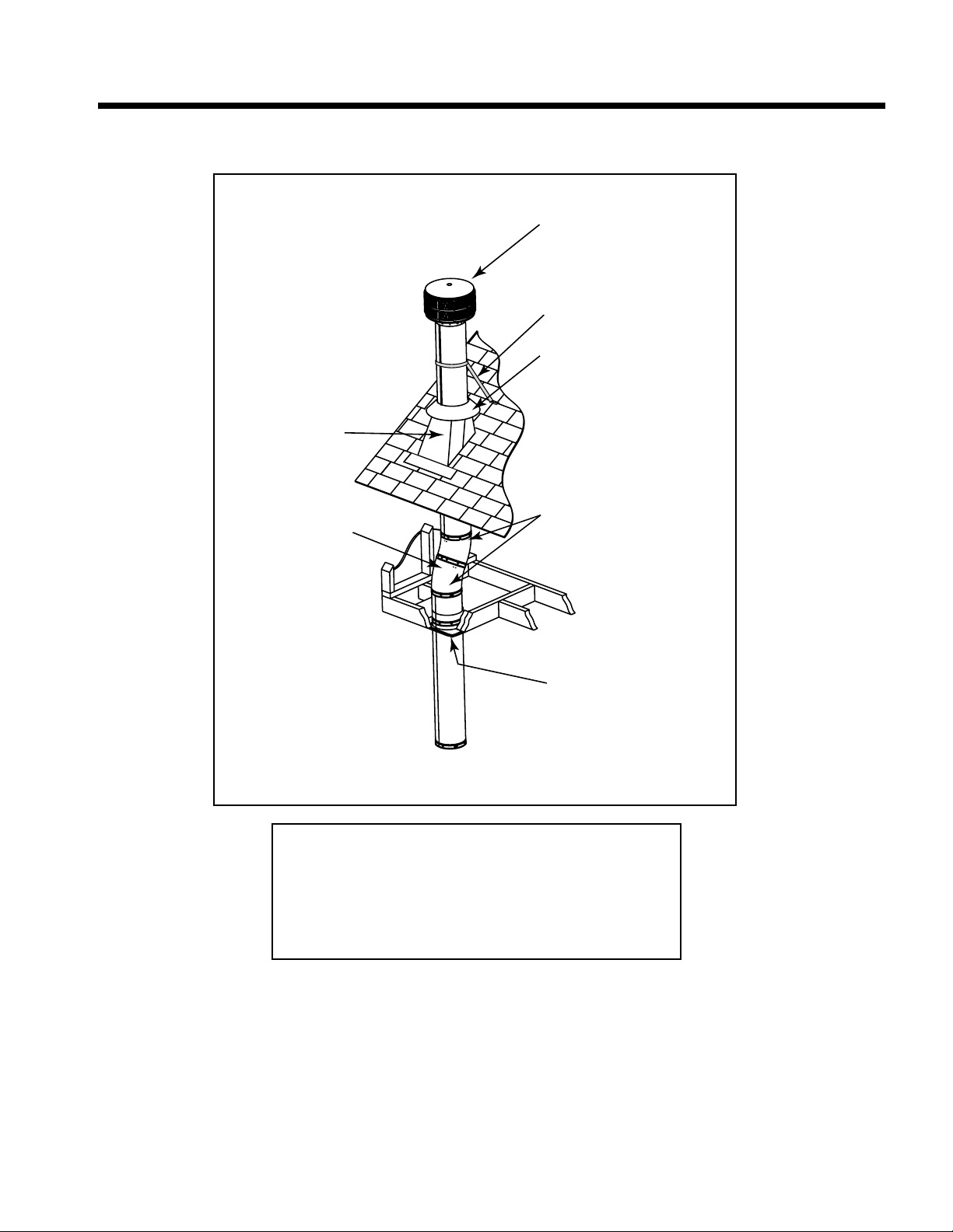
5
Chimney Assembly
5
Chimney must extend
beyond combustible
roof structure
Maintain minimum
height of chimney
above roof
Install roof flashing
according to minimum
requirements
Offsets/returns
may not exceed
30° from vertical
Lock chimney
sections together
firmly to resist
movement
Termination Cap
Additional
support for
tall chimneys
Storm Collar
Maintain minimum
clearances to
combustibles as
specified
Support straps for offsets/
returns must be secured
to adequate framing
Ceiling firestops
are required where
chimney passes
through ceiling or
floor
Figure 5.1 Typical Chimney System - Guidelines for Chimney System Installation
NOTE:
• Chimney performance may vary.
• Trees, buildings, roof lines and wind conditions affect
performance.
• Chimney height may need adjustment if smoking or
overdraft occurs.
16
Heat & Glo • Multi-Sided Woodburning Fireplace • 34977 Rev T • 11/07
 Loading...