

Heat & Glo LifeStyle 8000TVD User Manual
Model:
8000TVD
WARNING: IF THE INFORMATION
IN THESE INSTRUCTIONS IS NOT
FOLLOWED EXACTL Y, A FIRE OR
EXPLOSION MAY RESULT CAUSING PROPERTY DAMAGE, PERSONAL INJURY, OR DEATH.
- Do not store or use gasoline or other flammable vapors and liquids in the vicinity of this
or any other appliance.
- What to do if you smell gas
• Do not try to light any appliance.
• Do not touch any electrical switch.
• Do not use any phone in your building.
• Immediately call your gas supplier from a
neighbor's phone. Follow the gas supplier's
instructions.
• If you cannot reach your gas supplier, call
the fire department.
- Installation and service must be performed by a
qualified installer, service agency, or the gas
supplier.
Installers Guide
Underwriters
Laboratories Listed
READ THIS MANUAL BEFORE INSTALLING OR
OPERA TING THIS APPLIANCE. THIS INSTALLERS
GUIDE MUST BE LEFT WITH APPLIANCE FOR
FUTURE REFERENCE.
WARNING: IMPROPER INSTALLATION, ADJUSTMENT, ALTERATION,
SERVICE OR MAINTENANCE CAN
CAUSE INJURY OR PROPERTY DAMAGE. REFER TO THIS MANUAL. FOR
ASSIST ANCE OR ADDITIONAL INFORMATION CONSULT A QUALIFIED INST ALLER, SERVICE AGENCY , OR THE
GAS SUPPLIER.
Please contact your Heat-N-Glo dealer for any questions
or concerns. For the number of your nearest Heat-N-Glo
dealer, please call 1-888-427-3973.
Printed in U.S.A. Copyright 2004,
Heat-N-Glo, a brand of Hearth & Home T echnologies Inc.
20802 Kensington Boulevard, Lakeville, MN 55044
This product is covered by one or more of the following patents: (United States) 4,112,913; 4,408,594; 4,422,426; 4,424,792; 4,520,791; 4,793,322;
4,852,548; 4,875,464; 5,000,162; 5,016,609; 5,076,254 5,191,877; 5,218,953; 5,328,356; 5,429,495; 5,452,708; 5,542,407; 5,613,487; (Australia)
543790; 586383; (Canada) 1,123,296; 1,297,746; 2,195,264; (Mexico) 97-0457; (New Zealand) 200265; or other U.S. and foreign patents pending.
379-900I 1/04
1
SAFETY AND WARNING INFORMATION
READ and UNDERSTAND all instructions carefully
!
before starting the installation. FAILURE TO
FOLLOW these installation instructions may result
in a possible fire hazard and will void the warranty.
Prior to the first firing of the fireplace, READ the
!
Using Your Fireplace section of the Owners Guide.
DO NOT USE this appliance if any part has been
under water. Immediately CALL a qualified service
!
technician to inspect the unit and to replace any part
of the control system and any gas control which has
been under water.
THIS UNIT IS NOT FOR USE WITH SOLID FUEL.
!
Installation and repair should be PERFORMED by a
qualified service person. The appliance and venting
!
system should be INSPECTED before initial use
and at least annually by a professional service
person. More frequent cleaning may be required
due to excessive lint from carpeting, bedding
material, etc. It is IMPERATIVE that the unit’s
control compartment, burners, and circulating air
passageways BE KEPT CLEAN to provide for
adequate combustion and ventilation air.
These units MUST use one of the vent systems
described in the Installing the Fireplace section of
!
the Installers Guide. NO OTHER vent systems or
components MAY BE USED.
This gas fireplace and vent assembly MUST be
!
vented directly to the outside and MUST NEVER be
attached to a chimney serving a separate solid fuel
burning appliance. Each gas appliance MUST USE
a separate vent system. Common vent systems are
PROHIBITED.
INSPECT the external vent cap on a regular basis to
!
make sure that no debris is interfering with the air
flow.
The glass door assembly MUST be in place and
!
sealed, and the trim door assembly MUST be in
place on the fireplace before the unit can be placed
into safe operation.
DO NOT OPERA TE this appliance with the glass
!
door removed, cracked, or broken. Replacement of
the glass door should be performed by a licensed
or qualified service person. DO NOT strike or slam
the glass door.
Always KEEP the appliance clear and free from
!
combustible materials, gasoline, and other
flammable vapors and liquids.
NEVER OBSTRUCT the flow of combustion and
!
ventilation air. Keep the front of the appliance
CLEAR of all obstacles and materials for servicing
and proper operations.
Due to the high temperature, the appliance should
be LOCATED out of traffic areas and away from
!
furniture and draperies. Clothing or flammable
material SHOULD NOT BE PLACED on or near the
appliance.
Children and adults should be ALERTED to the
!
hazards of high surface temperature and should
ST AY AWAY to avoid burns or clothing ignition.
Young children should be CAREFULL Y SUPERVISED
when they are in the same room as the appliance.
The glass door assembly SHALL ONLY be
!
replaced as a complete unit, as supplied by the gas
fireplace manufacturer. NO SUBSTITUTE material
may be used.
DO NOT USE abrasive cleaners on the glass door
!
assembly. DO NOT ATTEMPT to clean the glass
door when it is hot.
Turn off the gas before servicing this appliance. It is
recommended that a qualified service technician
!
perform an appliance check-up at the beginning of
each heating season.
Any safety screen or guard removed for servicing
!
must be replaced before operating this appliance.
DO NOT place furniture or any other combustible
!
household objects within 36 inches of the fireplace
front.
2

TABLE OF CONTENTS
Safety and Warning Information. ................................................ 2
u
Service Parts List. ....................................................................... 4
Section 1: Approvals and Codes ................................................ 8
Appliance Certification.................................................................... 8
Installation Codes ........................................................................... 8
High Altitude Installations ................................................................ 8
Section 2: Getting Started .......................................................... 9
Introducing the Heat-N-Glo Gas Fireplaces ................................... 9
Pre-installation Preparation ............................................................ 9
Section 3: Installing the Fireplace............................................11
Step 1 Locating the Fireplace ...................................................11
Step 2 Framing the Fireplace....................................................11
Step 3 Negative Pressure Make-up Air .................................... 12
Step 4 Installing the Vent System............................................. 13
A. Vent System Approvals............................................ 13
B. System Components .............................................. 13
C. Bedroom Installation in Canada.............................. 14
D. Vent Termination...................................................... 14
Step 5 Positioning, Leveling, and
Securing the Fireplace.................................................. 14
Step 6 The Gas Control Systems............................................ 14
u
Step 7 The Gas Supply Line .................................................... 15
Step 8 Gas Pressure Requirements ....................................... 15
u
Step 9 Wiring the Fireplace...................................................... 16
Step 10 Finishing........................................................................ 18
Step 11 Installing Trim, Logs, and Ember Material .................... 18
Installing the Trim .......................................................... 18
Positioning the Logs ..................................................... 18
Shutter Settings ............................................................ 18
Placing the Ember Material........................................... 18
Glass Specifications....................................................... 19
Step 12 Before Lighting the Fireplace........................................ 19
Step 13 Lighting the Fireplace.................................................... 19
After the Installation ...................................................................... 19
Section 4: Maintaining and Servicing Your Fireplace. ........ 20
u = Contains updated information.
3
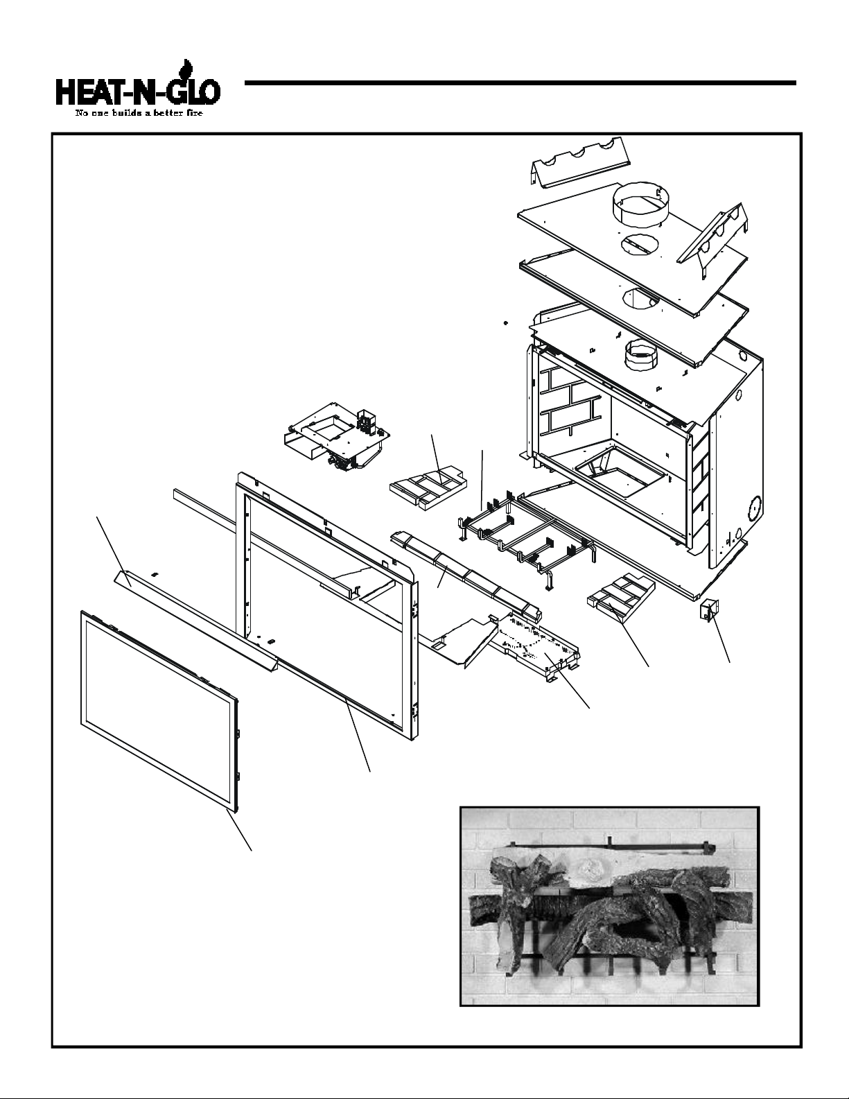
Service Parts
8000TVD
(NG, LP) Exploded Parts Diagram
(GN, PL) Vue éclatée des pièces
6
Beginning Manufacturing Date: 9-97
Ending Manufacturing Date: ______
4
8
3
18
5
9 Log Set Assembly
17
12
2
10
7
14
1
11
15
Part number list on following page.
*
La liste des numéros de pièce se trouve à la page suivante.
*
4
13
16
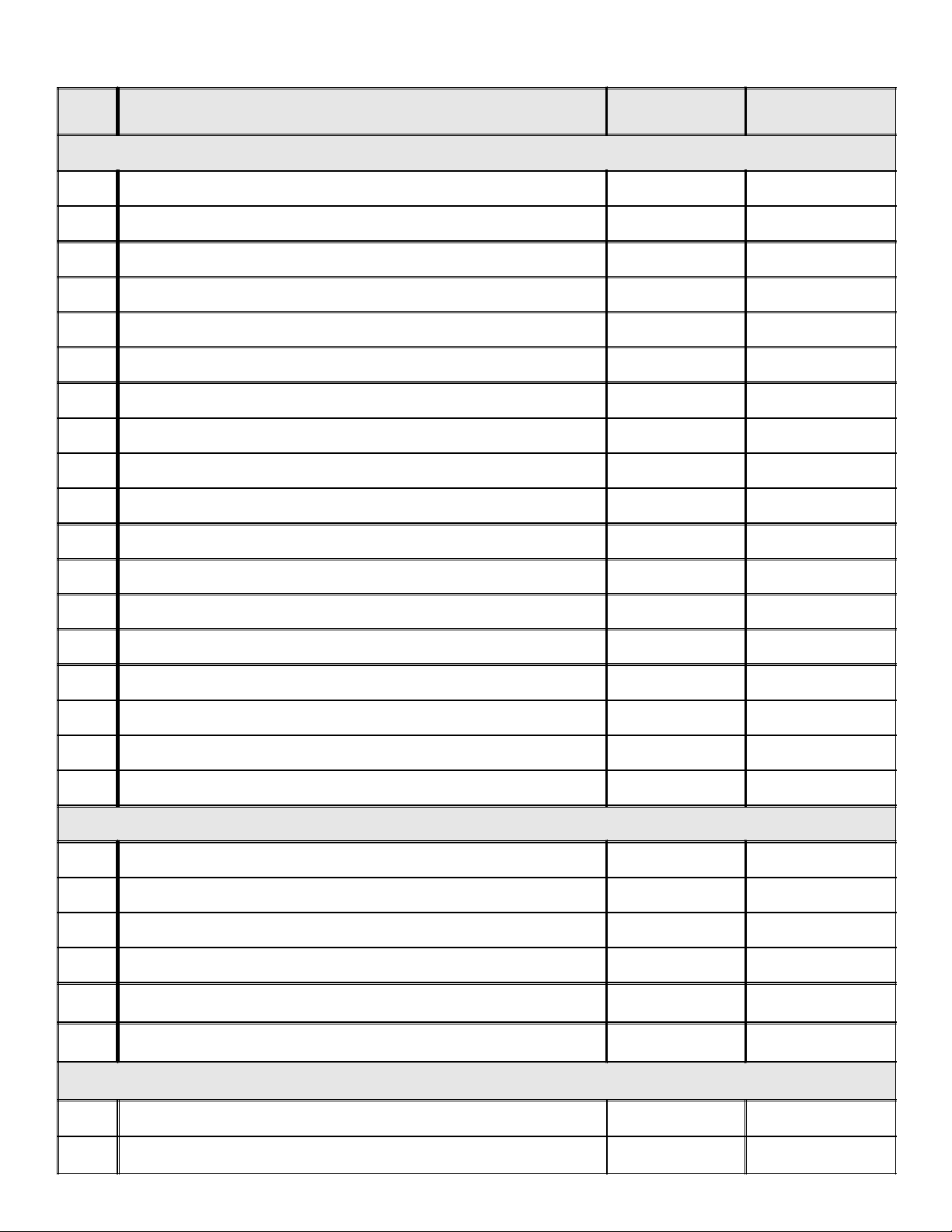
(NG, LP) Service Parts List / (GN, PL) Liste des pièces de rechange
8000TVD
ITEM /
PIÈCE
ENGLISH / FRENCH DESCRIPTION
SERIAL #
/ N° DE SÉRIE
PART NUMBER
/ N° DE PIÈCE
COMMON PARTS / PIÉCES COMMUNES
1 Junction Box - Pilot / Boîtier de raccordement - de veilleuse
PRE 002324001
POST 002324001
100-250A
4021-013
2 Burner / Brûleur 380-378A-UM
3 Glass Door Assembly / Porte en verre GLA-8TRD
4 Grate Assembly / Grille 582-360A
5 Refractory Base / Réfractaire Base SRV582-370-UM
6 Refractory Left Base / Réfractaire SRV582-376-UM
7 Refractory Right Base / Réfractaire SRV582-377-UM
8 Hood / Hotte SRV560-175
9 Log Set Assembly / Jeu de Bûches LOGS-8TRC
10 Log 1 / Bûche 1 SRV582-701
11 Log 2 / Bûche 2 SRV582-703
12 Log 3 / Bûche 3 SRV582-702
13 Log 4 / Bûche 4 SRV582-704
14 Log 5 / Bûche 5 SRV402-701
15 Log 6 / Bûche 6 SRV582-706
16 Log 7 / Bûche 7 SRV582-707
17 Log 8 / Bûche 8 SRV582-705
18 Surround / Entourage 380-130
STANDING PILOT IGNITION / D’ALLUMAGE PAR VEILLEUSE
Pilot Orifice NG / Orifice de veilleuse GN 446-505
Pilot Orifice PL / Orifice de veilleuse PL 446-517
Thermocouple / Thermocouple 446-511
Thermopile / Thermopile 060-512
Conversion Kit NG / Module de conversion GN
Conversion Kit LP / Module de conversion PL
Pre 1252
Post 1252
Pre 1052
Post 1052
NGK-8TRD
NGK-8TVD-A
LPK-8TRD
LPK-8TVD-A
IPI IGNITION ONLY / ALLUMAGE IPI SEULEMENT
Conversion Kit LP - IPI / Module de conversion PL - IPI LPK-8TVD-IPI
Junction Box / Boîtier de dérivation
PRE 002324001
POST 002324001
5
383-250A
4021-013

Service Parts
8000TVD
Standing Pilot Ignition
Valve Assembly
7
(NG, LP) Exploded Parts Diagram
(GN, PL) Vue éclatée des pièces
Beginning Manufacturing Date: 9-97
Ending Manufacturing Date: ______
4
1
6
5
9
3
2
ITEM /
PIÈCE
1 Pilot Bracket / Parenthèse Pilote 530-164
2 ON/OFF Rocker Switch / Interrupteur à bascule MARCHE/ARRÊT 060-521A
3 Piezo Ignitor / Allumeur piézo 291-513
4 Pilot Assembly NG / Module de veilleuse GN 485-510A
4 Pilot Assembly LP / Module de veilleuse PL 485-511A
5 Valve Bracket / Parenthèse de Valve 550-169
6 Orifice NG (#32C) / Assemblée d'Orifice GN (#32C) 582-832
6 Orifice LP (#50C) / Assemblée d'Orifice PL (#50C) 582-850
7 Flex Ball Valve Assembly / Fléchir l'Assemblée de Soupape de Balle 302-320A
DESCRIPTION
8
SERIAL #
/ N° DE SÉRIE
PART NUMBER
/ N° DE PIÈCE
8 Valve NG / Valve GN 060-522
8 Valve LP / Valve PL 060-523
9 Flexible Gas Connector / Tuyau à gaz flexible 383-302A
6
 Loading...