

Heat & Glo LifeStyle 6000TRS-CE User Manual
Model:
6000TRS-CE
Installers Guide
WARNING: If the information in these
instructions is not followed exactly, a fi re
or explosion may result causing property
damage, personal injury, or death.
• Do not store or use gasoline or other fl am-
mable vapors and liquids in the vicinity of
this or any other appliance.
• What to do if you smell gas
- Do not try to light any appliance
- Do not touch any electrical switch. Do not
use any phone in your building.
- Immediately call your gas supplier from a
neighbor’s phone. Follow the gas supplier’s instructions.
- If you cannot reach your gas supplier, call
the fi re department.
• Installation and service must be performed
by a qualifi ed installer, service agency , or the
gas supplier.
0086
WARNING
HOT SURFACES!
Glass and other surfaces are hot during
operation AND cool down.
Hot glass will cause burns.
• DO NOT touch glass until it is cooled
• NEVER allow children to touch glass
• Keep children away
• CAREFULLY SUPERVISE children in same room as
fi replace.
• Alert children and adults to hazards of high temperatures.
High temperatures may ignite clothing or other fl ammable
materials.
• Keep clothing, furniture, draperies and other fl ammable
materials away.
This appliance has been supplied with an integral barrier
to prevent direct contact with the fi xed glass panel. DO
NOT operate the appliance with the barrier removed.
READ THIS MANUAL BEFORE INSTALLING OR
OPERATING THIS APPLIANCE. THIS INSTALLERS
GUIDE MUST BE LEFT WITH APPLIANCE FOR FUTURE
REFERENCE.
Î
This is a room sealed appliance and no other ventilation is
required than what is provided.
Please contact your Heat & Glo dealer with any questions or
concerns. For the number of your nearest Heat & Glo dealer,
please visit www.heatnglo.com.
Printed in U.S.A. Copyright 2011
Heat & Glo, a brand of Hearth & Home Technologies Inc.
7571 215th Street West, Lakeville, MN 55044, USA
This product is covered by one or more of the following patents: (United States) 5328356, 5601073, 5613487, 5647340, 5890485, 5941237, 5947112,
5996575, 6006743, 6019099, 6053165, 6145502, 6170481, 6374822, 6484712, 6601579, 6769426, 6863064, 7077122, 7098269, 7258116, 7470729 or
other U.S. and foreign patents pending.
Heat & Glo • 6000TRS-CE • 2049-900 Rev. Q • 2/111
These instructions are only valid if the following country symbol is
on the appliance. If this symbol is not present on the appliance,
it is necessary to refer to the technical instructions which will
provide the necessary information concerning the modifi cation
of the appliance to the conditions of use for the country.
These instructions are valid for the following countries: GB, IE
SAFETY AND WARNING INFORMATION
READ and UNDERST AND all instructions carefully before starting the installation. FAILURE
TO FOLLOW these installation instructions may result in a possible fi re hazard and will
!
void the warranty.
Prior to the fi rst fi ring of the fi replace, READ the Using Your Fireplace section of the Users
!
Guide.
DO NOT USE this appliance if any part has been under water. Immediately CALL a qualifi ed
!
service technician to inspect the unit and to replace any part of the control system and any
gas control which has been under water.
THIS UNIT IS NOT FOR USE WITH SOLID FUEL.
!
Installation and repair should be PERFORMED by a qualifi ed service person. The appliance
!
and fl ue system should be INSPECTED before initial use and at least annually by a
professional service person.
Always KEEP the appliance clear and free from combustible materials, petrol, and other
!
fl ammable vapors and liquids.
NEVER OBSTRUCT the fl ow of combustion and ventilation air. Keep the front of the
!
appliance CLEAR of all obstacles and materials for servicing and proper operations.
Due to the high temperature, the appliance should be LOCATED out of traffi c areas and
!
away from furniture and draperies. Clothing or fl ammable material SHOULD NOT BE
PLACED on or near the appliance.
Children and adults should be ALERTED to the hazards of high surface temperature
!
and should STAY AWAY to avoid burns or clothing ignition. Young children should be
CAREFULLY SUPERVISED when they are in the same room as the appliance.
These units MUST use one of the fl uing systems described in the Installing the Fireplace
!
section of the Installers Guide. NO OTHER fl ue systems or components MAY BE USED.
This gas appliance and fl ue assembly MUST be vented directly to the outside and MUST
!
NEVER be attached to a chimney serving a separate solid fuel burning appliance. Each gas
appliance MUST USE a separate fl ue system. Common fl ue systems are PROHIBITED.
INSPECT the external terminal cap on a regular basis to make sure that no debris is
!
interfering with the air fl ow.
The glass door assembly MUST be in place and sealed, and the trim door assembly MUST
!
be in place on the appliance before the unit can be placed into safe operation.
DO NOT OPERATE this appliance with the glass door removed, cracked, or broken.
!
Replacement of the glass door should be performed by a licensed or qualifi ed service
person. DO NOT strike or slam the glass door.
The glass door assembly SHALL ONL Y be replaced as a complete unit, as supplied by the
!
gas appliance manufacturer. NO SUBSTITUTE material may be used.
DO NOT USE abrasive cleaners on the glass door assembly . DO NOT ATTEMPT to clean
!
the glass door when it is hot.
Turn off the gas before servicing this appliance. It is recommended that a qualifi ed service
!
technician perform an appliance check-up at the beginning of each heating season.
Any safety screen or guard removed for servicing must be replaced before operating
!
this appliance.
This appliance is intended for use on a gas installation with a governed meter.
!
Heat & Glo • 6000TRS-CE • 2049-900 Rev. Q • 2/112

Safety and Warning Information ...................................2
Service Parts List ...........................................................4
Section 1: Approvals and Regulations .........................7
Appliance Certifi cation ..................................................7
Installation Regulations ................................................7
Section 2: Getting Started .............................................8
Introducing the Heat & Glo Gas Fireplaces ..................8
Pre-installation Preparation ..........................................8
Section 3: Installing the Fireplace ..............................10
Step 1 Locating the Fireplace ..................................10
Step 2 Framing the Fireplace ...................................11
Step 3 Installing the Flue System .............................12
A. Flue System Approvals .............................12
B. Installing Flue Components ......................20
C. Flue Termination .......................................24
Table of
Contents
Step 4 Positioning, Leveling and
Securing the Fireplace ..................................29
Step 5 The Gas Control Systems .............................29
Step 6 The Gas Supply Line ....................................30
Step 7 Gas Pressure Requirements ........................31
Step 8 Wiring the Fireplace ......................................31
Step 9 Finishing .......................................................32
Step 10
Installing the Trim ..........................................33
Positioning the Logs .....................................34
Placing the Ember Material ...........................36
Step 11 Before Lighting the Fireplace ........................37
Step 12 Lighting the Fireplace ...................................38
After the Installation .....................................38
Section 4: Maintaining and Servicing
Your Fireplace ............................................39
Installing Trim, Logs & Ember Material
............33
Section 5: Troubleshooting .........................................41
Limited Lifetime Warranty ...............................................44
Î = Contains updated information.
Heat & Glo • 6000TRS-CE • 2049-900 Rev. Q • 2/11 3
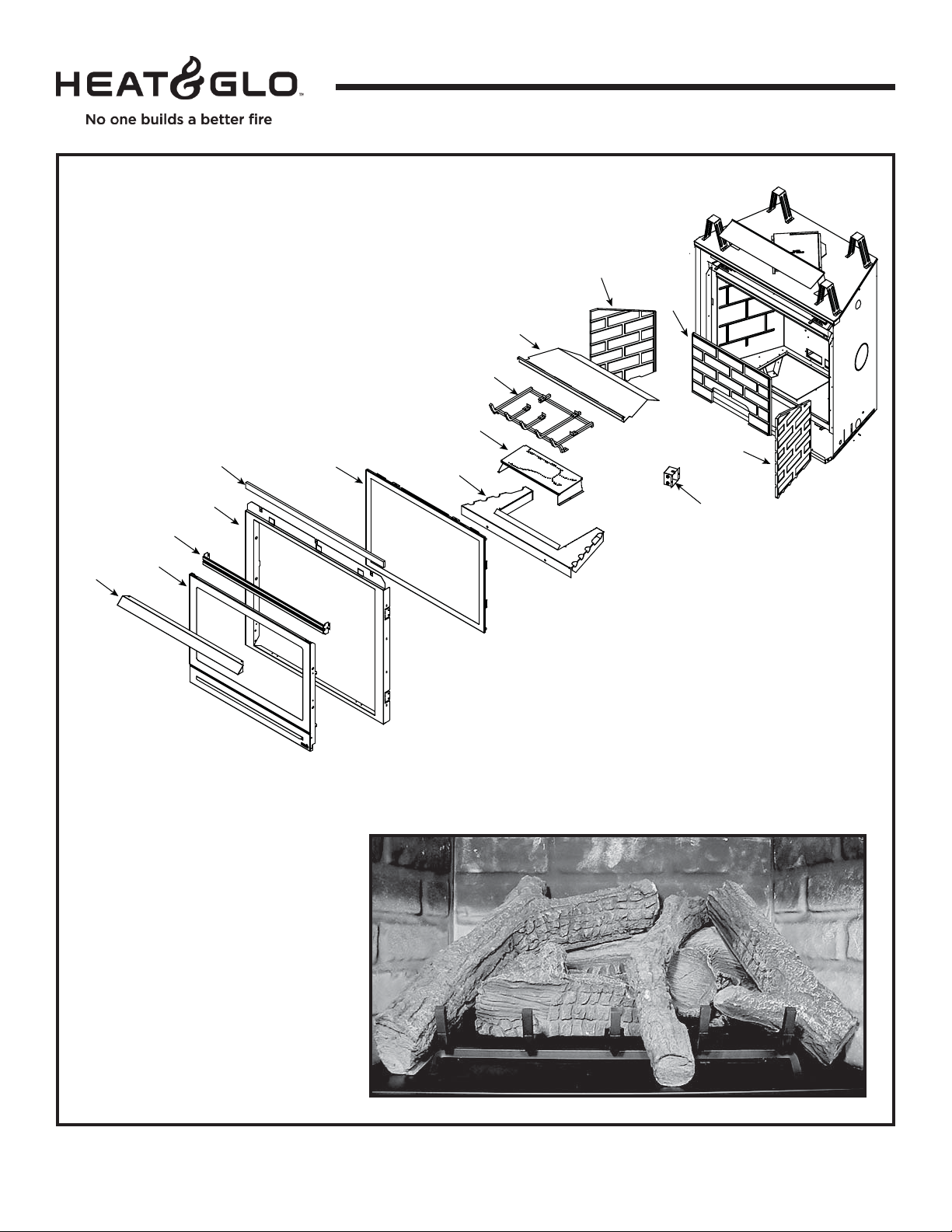
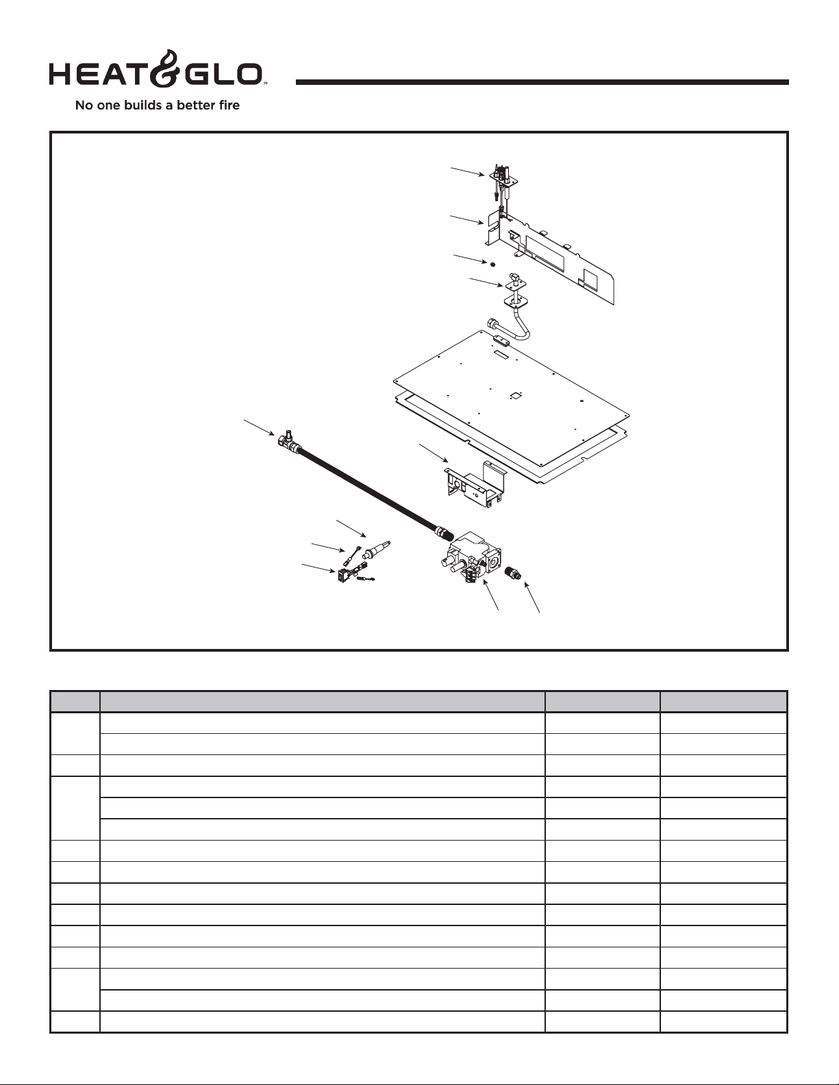
Service Parts
6000TRS-CE
17
15
16
36” Direct Vent Gas Fireplace
11
12
14
13
Beginning Manufacturing Date: Jan 2004
Ending Manufacturing Date: ______
9
8
10
7
6
19
18
Log Set Assembly
4
2
3
1
5
Part number list on following page.
Heat & Glo • 6000TRS-CE • 2049-900 Rev. Q • 2/114
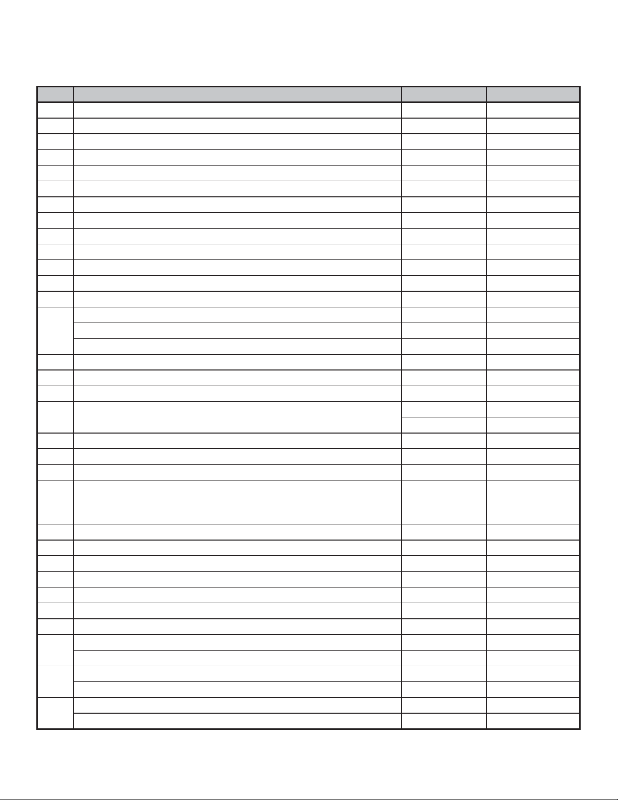
Service Parts List 6000TRS-CE
IMPORTANT THIS IS DATED INFORMATION: When requesting service or replacement parts for your appliance please
provide model number and serial number. All parts listed in this manual may be ordered from an authorized dealer.
ITEM DESCRIPTION COMMENTS PART NUMBER
Log Set Assembly LOGS-6TRSCE
1
2
3
4
5
6
7
8
9
10
11
12
13
14
15
16 Surround
17
18
19
Î
Additional service part numbers appear on following page.
Log #1 SRV2049-700
Log #2 SRV2049-701
Log #3 SRV385-723
Log #4 SRV385-721
Log #5 SRV385-722
Junction Box 546-250A
Refractory Kit BRICK-6000-FB
Refractory, Right SRV2027-372
Refractory, Back SRV2027-370
Refractory, Left SRV2027-371
Exhaust Baffl e 2049-101
Grate 2049-020
Burner Assembly N 2049-010
Burner Assembly P 2049-012
Burner Assembly B 2049-014
Base Refractory 2049-102
Glass Door Assembly GLA-6TRXI
Insulation Board 385-401
Pre Aug 2009 SRV2101-260
Post Aug 2009 2166-019
Top Louver 392-182A
Dress Guard 392-180A
Hood SRV60-143-BK
Gasket Assembly
Contains Burner neck, shutter bracket, vent, seal cap, and valve
plate gaskets
Glass Latch Assembly Pkg of 2 33858/2
High Temp Limit Switch 046-018A
Exhaust Restrictor 530-299
Mineral Wool 050-721
Touch-Up Paint TUP-GBK-12
Conversion Kits
Natural to Propane NGK-6TRS-CE
Propane to Butane LPK-6TRS-CE
Butane to Propane BGK-6TRS-CE
Regulator N 230-1570
Regulator P/B 230-1520
Pilot Orifi ce N 529-512
Pilot Orifi ce P/ B 200-2630
2166-081
Heat & Glo • 6000TRS-CE • 2049-900 Rev. Q • 2/11 5
Service Parts
6000TRS-CE
Valve Assembly
20.6
Valve Assemble Parts List
20.1
20.2
20.3
20.5
Beginning Manufacturing Date: Jan 2004
Ending Manufacturing Date: ______
20.4
20.7
20.8
20.9
20.10
IMPORTANT THIS IS DATED INFORMATION: When requesting service or replacement parts for your appliance please
provide model number and serial number. All parts listed in this manual may be ordered from an authorized dealer.
ITEM DESCRIPTION COMMENTS PART NUMBER
20.1
20.2 Pilot Bracket 2049-105
20.3
20.4 12” Flex 383-302A
20.5 Valve Bracket 2118-104
20.6 Flex Assembly 302-330A
20.7 Piezo Ignitor 291-513
20.8 Wire Assembly 049-552A
20.9 On/ Off Rocker Switch 060-521A
20.10
20.11 Male Connector
Pilot Assembly N 529-550A
Pilot Assembly P/B 529-551A
Orifi ce N (#33C) 582-833
Orifi ce P (1.8 MM) 582-818
Orifi ce B (#52C) 582-852
Valve N 060-524
Valve P 060-526
20.11
Pkg of 5 303-315/5
Heat & Glo • 6000TRS-CE • 2049-900 Rev. Q • 2/116
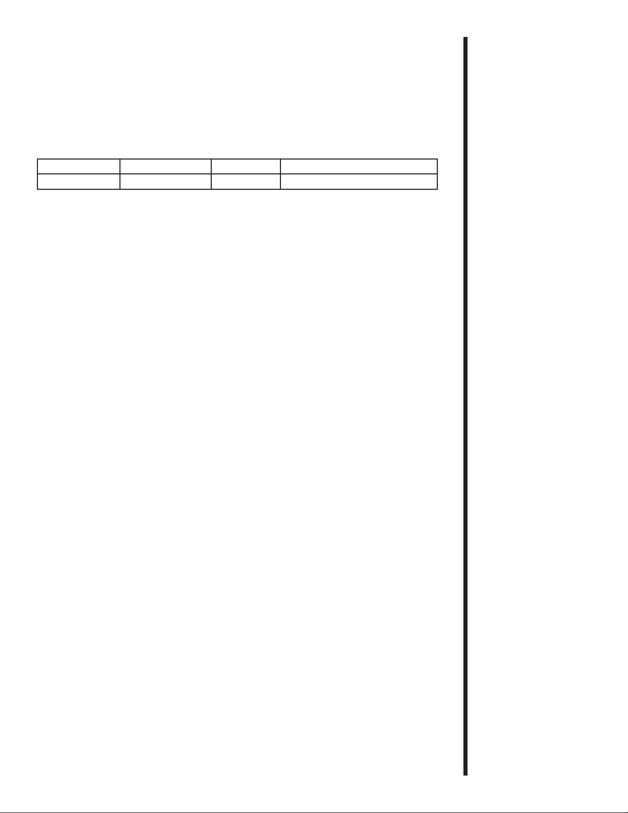
Appliance Certifi cation
The Heat & Glo fi replace models discussed in this
Installers Guide have been tested to certifi cation
standards and listed by the applicable laboratories.
MODEL LABORATORY TYPE CERTIFICATION STANDARD
Î
6000TRS-CE
Installation Regulations
Before installation check that local distribution conditions, nature of gas and
pressure, and adjustment of the appliance are compatible.
This appliance must be installed with the rules in force, and used only in a
suffi ciently ventilated space. Consult instructions before installation and use of
this appliance.
BSI Gas Fireplace BS EN 613:2001 (Amd 1)
1
Approvals
and
Regulations
Heat & Glo • 6000TRS-CE • 2049-900 Rev. Q • 2/11 7

Introducing the
Heat & Glo
Gas Fireplaces
Heat & Glo direct fl ue gas fi replaces are designed to
operate with all combustion air siphoned from outside
of the building and all exhaust gases expelled to the
outside.
The information contained in this Installers Guide,
unless noted otherwise, applies to all models and gas
control systems.
2
Getting
Started
Pre-installation
Preparation
Gas fi replace diagrams, including the dimensions, are
shown in this section.
This gas fi replace and its components are tested and
safe when installed in accordance with this Installers
Guide. Report to your dealer any parts damaged in
shipment, particularly the condition of the glass. Do
not install any unit with damaged, incomplete, or
substitute parts.
The flue system components and trim doors are
shipped in separate packages. The gas logs are
packaged separately and must be fi eld installed.
Read all of the instructions before starting the
installation. Follow these instructions carefully
during the installation to ensure maximum safety
and benefi t. Failure to follow these instructions
will void the owner’s warranty and may present
a fi re hazard.
The Heat & Glo Fireplace Products, Inc. Warranty
will be voided by , and Heat & Glo Fireplace Products,
Inc. disclaims any responsibility for, the following
actions:
• Installation of any damaged fi replace or fl ue system
component.
• Modifi cation of the fi replace or direct fl ue system.
• Installation other than as instructed by Heat & Glo
Fireplace Products, Inc.
• Improper positioning of the gas logs or the glass
door.
• Installation and/or use of any component part not
manufactured and approved by Heat & Glo Fireplace
Products, Inc., not withstanding any independent
testing laboratory or other party approval of such
component part or accessory.
ANY SUCH ACTION MAY POSSIBLY CAUSE A FIRE
HAZARD.
Heat & Glo • 6000TRS-CE • 2049-900 Rev. Q • 2/118
When planning a fi replace installation, it’s necessary to determine:
• Where the unit is to be installed.
• The fl ue system confi guration to be used.
• Gas supply piping.
• Electrical wiring.
• Framing and fi nishing details.
• Whether optional accessories—devices such as a fan, wall switch, or remote control—are
desired.
If the fi replace is to be installed on carpeting or tile, or on any combustible material other
than wood fl ooring, the fi replace should be installed on a metal or wood panel that extends
the full width and depth of the fi replace.
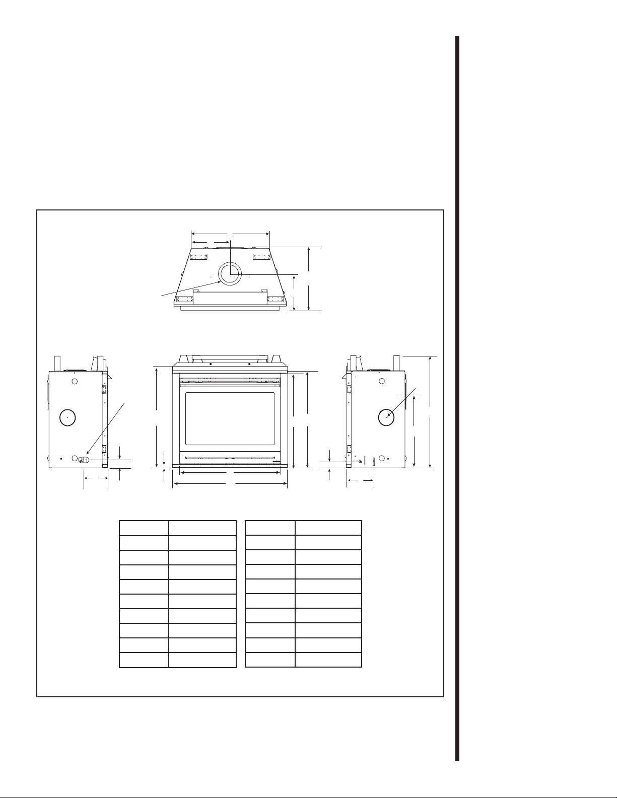
L
M
C
L
N
TOP VIEW
J
K
GAS LINE
ACCESS
R
O
P
LEFT SIDE RIGHT SIDE
Location Centimeters
Q
B
A
FRONT VIEW
A 104,1
B 91,8
C 85,1
D 87,9
E57
F 24,6
G 68,3
H 15,2 dia
I 101,9
Location Centimeters
J 54,6
K 29,7
L 72,4
M 36,2
N 21,6
O73
P 21,6
Q25
R 91,8
D
C
E
F
H
C
L
I
G
Figure 1. Diagram of the 6000TRS-CE
Heat & Glo • 6000TRS-CE • 2049-900 Rev. Q • 2/11 9
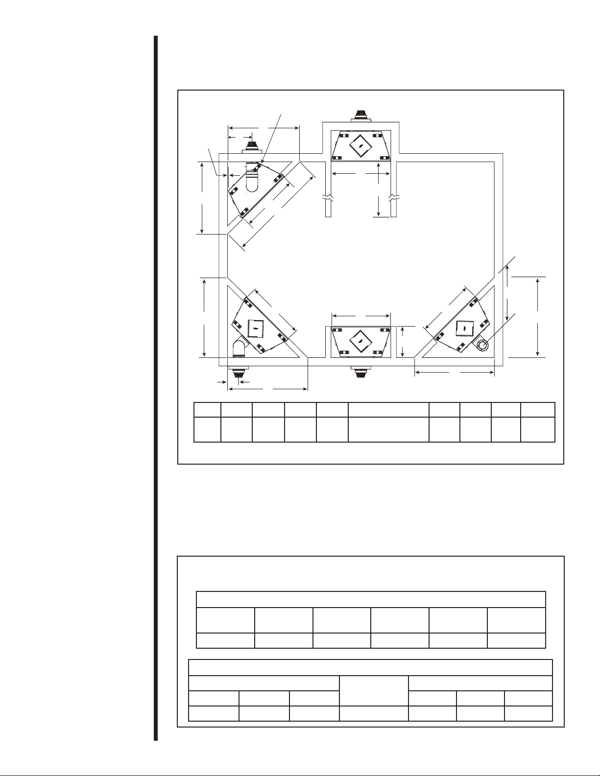
Step 1
Locating the
Fireplace
NOTE: THE REAR STANDOFF MAY NEED
TO BE REMOVED WHEN VENTING AT 45º
1,3 cm
G
The diagram below shows space and clearance
requirements for locating a fi replace within a room.
A
3
Installing the
Fireplace
A
D
H
ABCD E FGH I
cm 130 107 183 144
B
C
TOP FLUE
ONE 90º ELBOW
REAR FLUE,
HORIZONTAL TERMINATION
TWO 90º ELBOWS
B
D
B
ALCOVE
INSTALLATION
NO ELBOWS
E
REAR FLUE
B
See Section F.
Mantel Projections
REAR FLUE
ONE 90º ELBOW
F
I
B
D
56 45 20 73
C
L
D
Figure 2. Fireplace Dimensions, Locations, and Space Requirements
Clearance Requirements
The top and back of the fi replace are defi ned by stand-offs.
The minimum clearance to a perpendicular wall extending past the face of the fi replace is
7.62 cm.
The back of the fi replaces may be recessed into combustible construction (see Figure 3).
MODEL: 6000TRS-CE RECESSED DEPTH: 54.6 cm
Minimum Clearances from the Fireplace to Combustible Materials
Glass
Front
91.4 cm 0 1.3 cm 1.3 cm 8.9 cm 79 cm
Minimum Clearances from the Flue Pipe to Combustible Materials
For Horizontal Sections
Top Bottom Sides Top Bottom Sides
7.6 cm 2.54 cm 2.54 cm 2.54 cm 6.4 cm 1.3 cm 2.54 cm
Figure 3. Minimum Clearances
Floor
Back of
Fireplace
For Vertical
Sides of
Fireplace
Sections
Top of
Fireplace
At Wall Firestops
Ceiling
Heat & Glo • 6000TRS-CE • 2049-900 Rev. Q • 2/1110
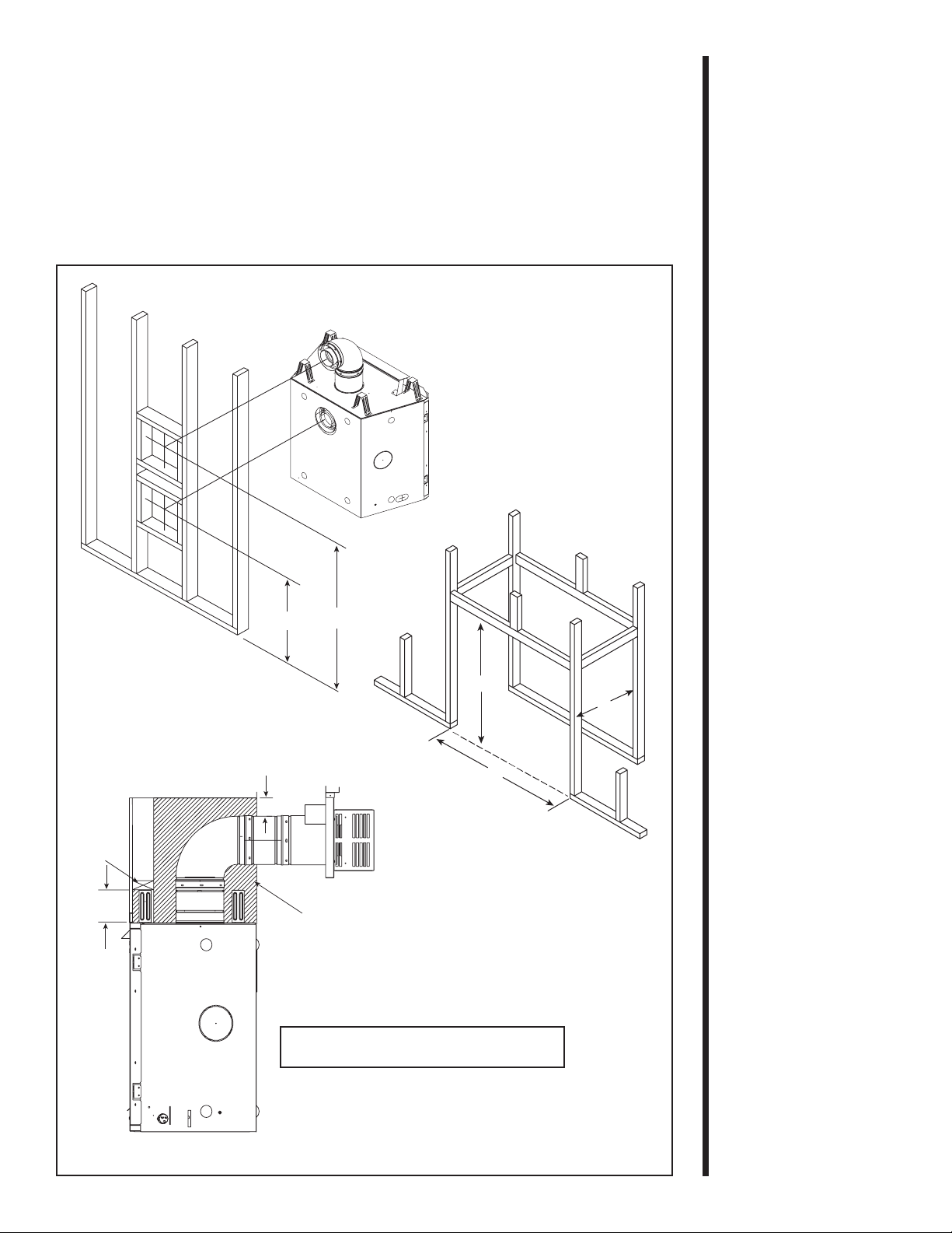
Step 2
Framing the
Fireplace
Fireplace framing can be built before or after the fi replace is
set in place. Framing should be positioned to accommodate
wall coverings and fi replace facing material. The diagram
below shows framing reference dimensions.
CAUTION
MEASURE FIREPLACE DIMENSIONS, AND VERIFY
FRAMING METHODS AND WALL COVERING
DETAILS, BEFORE FRAMING CONSTRUCTION
BEGINS.
D*
E*
WALL
STUD
14 cm
B
Framing should be
constructed of 2 X 4
lumber or heavier.
8 cm
NON-COMBUSTIBLE ZONE
IS DEFINED BY 8 CM ABOVE
THE ELBOW FOR THE ENTIRE
WIDTH AND DEPTH (BEHIND
THE FRONT HEADER) OF
THE FIREBOX.
A B C D E
107 cm 102 cm 56 cm 68,3 cm 106 cm
* Note: Dimension B taken from fi n-
ished hearth frame. Dimensions D
and E taken from bottom of unit.
*
C
A
Figure 4. Framing Dimensions
Heat & Glo • 6000TRS-CE • 2049-900 Rev. Q • 2/11 11
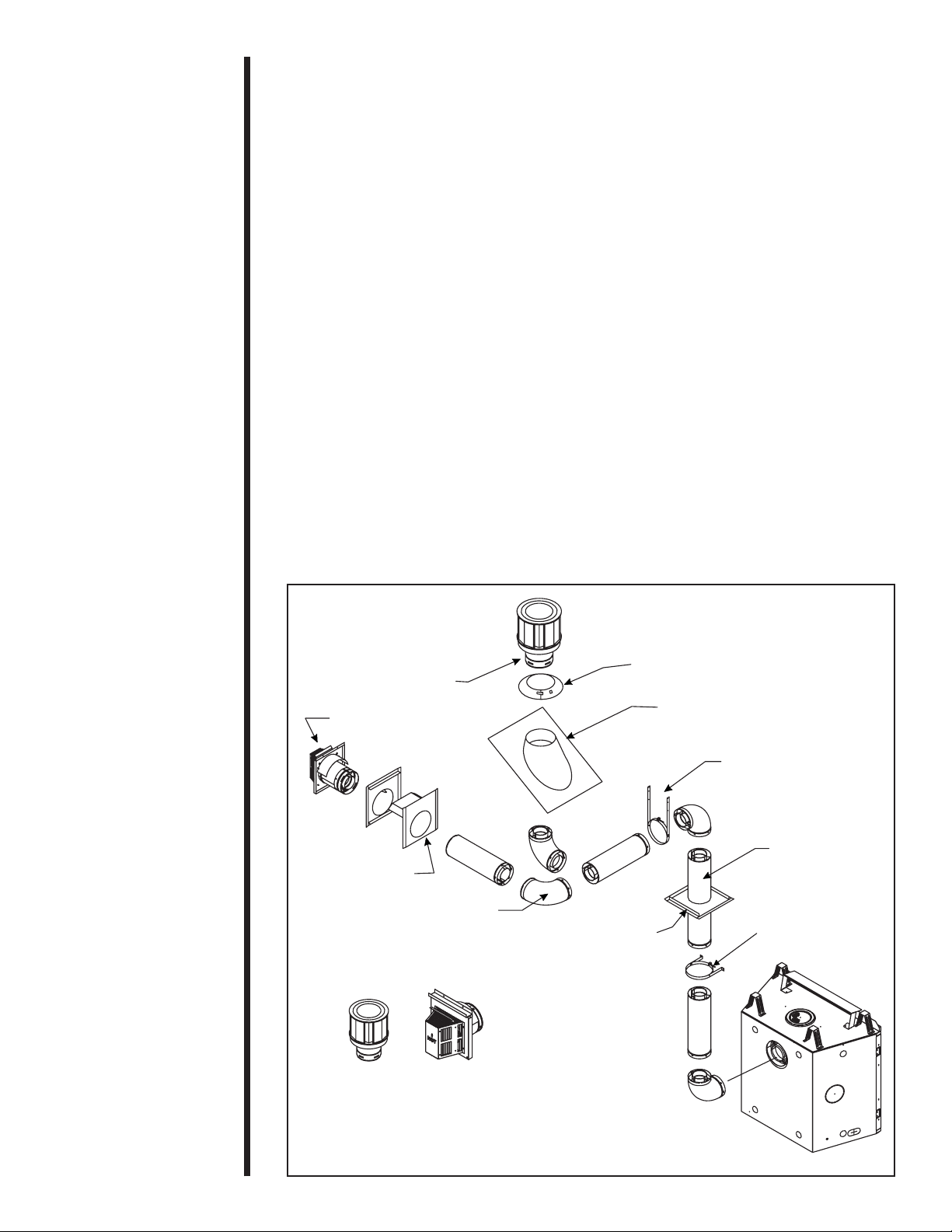
Step 3
Installing the
Flue System
A. Flue System Approvals
These models have fl ue starting collars on both the top and
the back of the unit. Depending upon the installation, decide
which ONE set of starting collars will be used to attached the
fl ue system. The starting collar sealing cap must remain on the
starting collar NOT used.
These models use DVP-series direct fl ue components when
using the TOP and REAR fl ue collars.
Approved fl ue system components are labeled for identifi cation.
NO OTHER FLUEING SYSTEMS OR COMPONENTS MAY
BE USED. Detailed installation instructions are included with
each fl ue termination kit and should be used in conjunction with
this Installers Guide. Figure 4 shows fl ue system components
and terminations.
Identifying Flue Components
The fl ue systems installed on this gas fi replace may include one,
two, or three 90° elbow assemblies. The relationships of vertical
rise to horizontal run in fl ue confi gurations using 90° elbows
MUST BE strictly
in the fl ueing drawings and tables on the next several pages.
Note: T wo 45° elbows may be used in place of one 90° elbow.
You MUST always maintain the MAXIMUM and MINIMUM rise-
to-run ratios in the fl ue system when using 45° elbows.
adhered to. The rise to run relationships are shown
VERTICAL
TERMINATION
HORIZONTAL
TERMINATION
WALL FIRESTOP
90 DEGREE
ELBOW
FLUE SYSTEM TERMINATION KITS
DVP-SERIES
DVP-TVHW
DVP-TRAP
STORM COLLAR
CEILING
FIRESTOP
ROOF FLASHING
HORIZONTAL PIPE
SUPPORT
PIPE LENGTH
WALL BRACKET
Figure 5. Flue Components and Terminations
Heat & Glo • 6000TRS-CE • 2049-900 Rev. Q • 2/1112
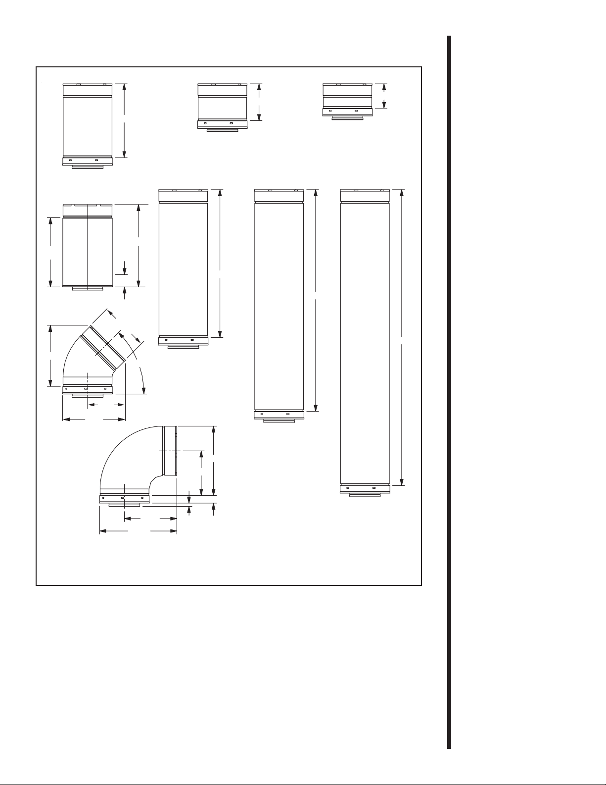
DVP12
30.5 cm
DVP6
15.2 cm
10.2 cm
DVP4
31.0 cm
MAX.
25.1 cm
DVP12A
26 cm
DVP45
26 cm
5.1 cm
MIN.
20.3
cm
36.2 cm
45.0º
31.9 cm
V
P
D
21.7 cm
0
9
S
61.0 cm
91.4 cm
121.9 cm
DVP24
DVP36
28.6 cm
18.4 cm
3.2 cm TYP
1.3 cm TYP
T
DVP48
NOTE: PIPES OVERLAP 3,2 cm A T EACH JOINT.
Figure 6. DVP-Series Balanced Flue Component Specifi cations (127 mm inner pipe / 203 mm outer pipe)
Heat & Glo • 6000TRS-CE • 2049-900 Rev. Q • 2/11 13
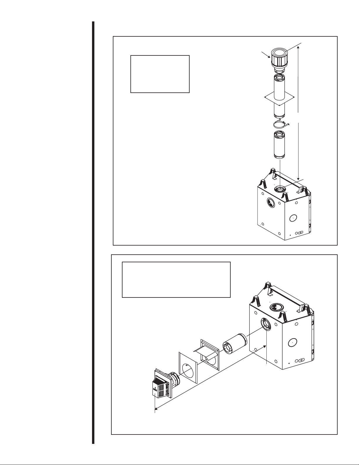
STRAIGHT UP
VERTICAL FLUE
V
11.8 m MAX.
CAP
V
Figure 7. Straight up Vertical Flue
STRAIGHT OUT HORIZONTAL FLUE
H H
MIN. RUN MAX. RUN
13.1” (33.2 cm) 24” (61.0 cm)
H
Figure 8. Straight Out Horizontal Flue
Heat & Glo • 6000TRS-CE • 2049-900 Rev. Q • 2/1114
 Loading...