

Page 1
RC-CON Remote Control System
ON
OFF
SIGNAL
LIGHT
ON/OFF
BUTTONS
WALL CLIP
SLO
T
12V
BATTERY
COMPARTMENT
FRONT BACK
- Installation and Operating Instructions -
Single-function wireless remote control system for operat
ing valves with on/off latching solenoids.
If you cannot read or understand these installation
instructions do not attempt to install or operate.
INTRODUCTION
This remote control system was developed to provide a
safe, reliable, and user-friendly remote control system for
gas heating appliances. The system is operated manually from the transmitter. The system operates on radio
frequencies (RF) within a 20 foot range using non-directional signals. The system operates on one of 255 security codes that are programmed into the transmitter at
the factory; the remote receiver must learn the transmitter
code prior to initial use.
Review THERMO SAFETY SECTION under RECEIVER section. This high temperature safety feature shuts
down the appliance when a potentially unsafe condi
tion exists.
-
-
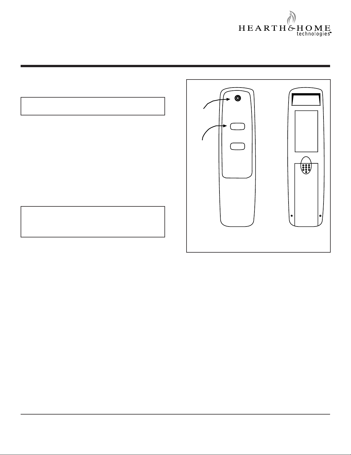
Figure 1. Remote Transmitter
Transmitter
This remote control system offers the user a battery-operated remote control to power an ON/OFF latching solenoid such as those used with gas valves used in some
decorative gas logs, gas fireplaces and other gas heating
appliances.
The circuit uses the battery power from the receiver to op
erate a latching solenoid. The circuit has reversing polarity software which reverses the positive (+) and negative
(-) output of the receiver’s battery power to drive solenoid
(ON/OFF FLAME) or open/close. The system is controlled
by the remote transmitter (see Figure 1).
Printed in U.S.A. • InD • Copyright 2005
Hearth & Home Technologies Inc.
20802 Kensington Boulevard, Lakeville, MN 55044
The transmitter operates on a 12V battery made specifically for remote controls and electronic lighters. Before
using the transmitter install the 12 volt (A-23) battery in
the battery compartment.
It is recommended that ALKALINE batteries always be
-
used for longer battery life and maximum operational per
-
formance.
The transmitter has ON and OFF functions that are acti
vated by pressing either button on the face of the transmitter. When a button on the transmitter is pressed, a signal
light on the transmitter illuminates to verify that a signal
is being sent. Upon initial use, there may be a delay of
three seconds before the remote receiver will respond to
the transmitter. This is part of the system’s design. If the
signal light does not illuminate, check the position of the
transmitter’s battery.
4004-301B 10/05
1
Page 2
Power setting - RC-CON
REMOTE
ON
OFF
LEARN
ADJ.
BATTERY COVER
SLIDES ON/OFF
FREQUENC Y ADJUSTIN G
ACCESS HOLE
LEARNING
BUTTON
SLIDE
SWITCH
ON
REMOTE
OFF
REQUIRES 4-A A 1.5V
ALKALINE B ATTERIE S
LEARN
ADJ.
REMOTE
O
FF
Functions
The electronics in the remote control system have the ca
pability of “powering” two different types of DC-powered
components. If any operational problems are noted contact Hearth & Home Technologies, Inc.
The RECEIVER comes from the factory programmed to
provide pulse DC voltage (5.5 VDC to 6.3 VDC) to a latch
ing solenoid.
Remote Receiver
IMPORTANT: The remote receiver should be positioned
where ambient temperatures do not exceed 130° F.
-
1. With the slide switch in the REMOTE position, the sys
tem will only operate if the remote receiver receives
commands from the transmitter. Upon initial use or after an extended period of no use, the ON button may
have to be pressed for up to three seconds before
activating solenoid. If the system does not respond to
-
the transmitter on initial use, see Matching Security
Codes.
2. With the slide in the OFF position, the system is off.
3. It is suggested that the slide switch be placed in the
OFF position if you will be away from your home for an
extended period of time. Placing the slide switch in the
OFF position also functions as a safety “lock out” by
both turning the system OFF and rendering the trans
-
mitter inoperative.
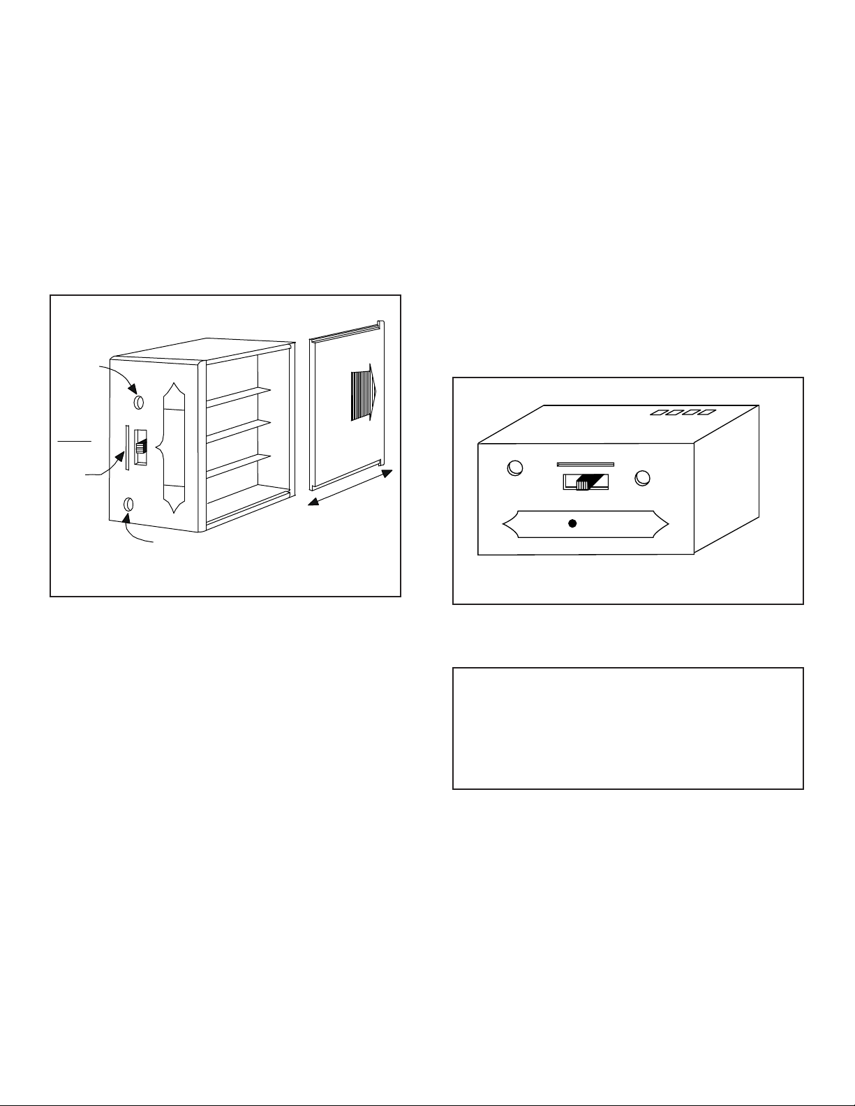
Figure 2. Remote Receiver
The remote receiver (See Figure 2) operates on four 1.5V
AA-size batteries. It is recommended that ALKALINE batteries be used for longer battery life and maximum microprocessor performance. IMPORTANT: New or fully
charged batteries are essential to proper operation of the
remote receiver as a latching solenoid power consumption is substantially higher than standard remote control
systems.
NOTE: The remote receiver will only respond to the transmitter when the 2-position slide button on the remote receiver is in the REMOTE position. The remote receiver
houses the microprocessor that responds to commands
from the transmitter to control system operation.
Figure 3. Slide Switch
INSTALLATION INSTRUCTIONS
WARNING
to 110-120VAC power. This will burn out the receiver.
Follow instructions from manufacturer of gas valve
for correct wiring procedures. Improper installation of
electric components can cause damage to gas valve
and remote receiver.
The remote receiver can be mounted on or near the fire
place hearth. PROTECTION FROM EXTREME HEAT IS
VERY IMPORTANT. Like any piece of electronic equipment, the remote receiver should be kept away from
temperatures exceeding 130º F inside the receiver case.
Battery life is also significantly shortened if batteries are
exposed to high temperatures.
Make sure the remote receiver switch is in the OFF posi
tion. For best results it is recommended that 18 gauge
stranded wires should be used to make connections and
should be no longer than 20 ft.
: Do not connect remote receiver directly
-
-
2
Page 3

WIRING INSTRUCTIONS
OFF
Latching
Solenoid
1/4 in. Female
Terminal
1/4 in. Female
Terminal
1/4 in. Female
Terminal
1/4 in. Female
Terminal
(Back of Receiver)
LEARN
ADJ.
Thermo-safety feature - receiver (T/S - RX)
Connecting the receiver to a valve with the latching
solenoid:
1. Connect the BLACK 18 gauge stranded wire with
the 1/4 inch female terminal from the receiver to the
BLACK wire with the 1/4 inch male terminals from the
valve solenoid (see Figure 4).
2. Connect the RED 18 gauge stranded wire with the 1/4
inch female terminal from the receiver to the RED wire
with the 1/4 inch male terminals from the valve solenoid.
3. After receiver wires are connected to the valve sole
noid wire make sure the receiver shield is located over
the receiver and then locate the receiver in an area
that will not exceed the 130° F.
IMPORTANT NOTE: Operation of these controls is de
pendent on which wire is attached to which terminal. If
operation of control does not correspond to operating buttons on transmitter, reverse wire installation at the receiver or at the control.
NOTE: Up to 6.3 VDC of power is provided at the receiver
terminal.
When the ambient temperature at the THERMISTOR, in
side the receiver case, reaches 130° F, the THERMISTOR will automatically send 2 pulses of power to the off
terminal on the valve to shut the fireplace system off and
the RECEIVER will begin emitting a series of 2 “beeps”
every 4 seconds.
When the ambient temperature, at the RECEIVER, drops
between 120° F and 130° F, the user can reactivate the
fireplace by pushing either button on the transmitter.
When any transmitter button is pressed, the THERMIS-
-
TOR “resets” itself and the fireplace will begin operating again. However, the “beeping” will continue, if the
ambient temperature remains between 120° F and 130°
F. This “beeping” alerts the user that the RECEIVER
should be repositioned so the ambient temperature
-
drops below 120° F.
When the temperature drops below 120° F, the “beep
ing” will cease, providing the user has “reset” the
THERMISTOR by pushing either transmitter button to
operate the fireplace. Allow sufficient time for receiver
to cool below 120° F, and then press transmitter button
to stop beeping.
Figure 4. Latching Solenoid
GENERAL INFORMATION
Matching security codes
Each transmitter can use one of 255 unique security
codes. It may be necessary to press the LEARN button
on the remote receiver to accept the transmitter security
code upon initial use, if batteries are replaced, or if a re
placement transmitter is purchased from your dealer or
the factory.
In order for the receiver to accept the transmitter secu
rity code, be sure the slide button on the receiver is in
the REMOTE position; the receiver will NOT “LEARN” if
the slide switch is in the OFF position. Press the LEARN
button on the remote receiver to accept the transmitter
security code by pressing in the LEARN button on the
front of the remote receiver and then pressing any button on the transmitter. A change in the beeping pattern,
at the receiver, indicates the transmitter’s code has been
accepted into the receiver. When an existing receiver has
accepted the new transmitter, the new security code will
overwrite the old one.
The microprocessor that controls the security code match
ing procedure is controlled by a timing function. If you are
unsuccessful in matching the security code on the first
attempt, wait 1 - 2 minutes before trying again. This delay
allows the microprocessor to reset its timer circuitry and
try up to two or three more times.
-
-
-
3
Page 4

Transmitter wall clip
WALL CLIP
SLOT
WALL CLI P
12V
BATTERY
COMPARTMENT
Battery life
The transmitter can be hung on a wall using the clip pro
vided (see Figure 5). If the clip is installed on a solid wood
wall, drill 1/8” pilot holes and install with the screws provided. If it is installed on a plaster/wallboard wall, first drill
two 1/4” holes into the wall. Then use a hammer to tap in
the two plastic wall anchors flush with the wall; then install
the screws provided.
-
Life expectancy of the alkaline batteries in the RC-CON
can be up to 12 months depending on use of the sole
noid function. Replace all batteries annually. When the
transmitter no longer operates the remote receiver from
a distance it did previously (i.e., the transmitter’s range
has decreased) or the remote receiver does not function
at all, the batteries should be checked. It is important that
the remote receiver batteries are fully charged, providing
combined output voltage of at least 5.0 volts. The transmitter should operate with as little as 9.0 volts battery
power.
NOTE: Extensive use of the Solenoid will reduce the
receiver’s battery life significantly.
TROUBLE SHOOTING
If you encounter problems with your fireplace system,
the problem may be with the fireplace itself or it could be
with the RC-CON remote system. Review the fireplace
manufacturer’s operation manual to make sure all connections are properly made. Then check the operation of
the remote in the following manner:
Figure 5. Wall Clip
Operation
1. This remote control will operate the gas valves latch
2. When the ON button is depressed the transmitter
3. When the OFF button is depressed the transmitter
4. The remote control will only work with the hand held
NOTE: Extensive use of the Latching Solenoid (ON/OFF)
will reduce the receiver’s battery life significantly.
ing solenoid to open the gas flow to full ON.
sends an RF signal to the receiver. The receiver then
sends a pulse of 6 volts of power to the solenoid. The
solenoid then opens the gas flow to the burner then to
full ON.
sends an RF signal to the receiver. The receiver then
sends a pulse of 6 volts of power to the solenoid. The
solenoid then closes the gas flow to the burner then to
full OFF.
transmitter. The receiver slide switch is only for posi
tive OFF or REMOTE operation.
1. Make sure the batteries are correctly installed in the
RECEIVER. One reversed battery will keep receiver
from operating properly.
2. Check battery in TRANSMITTER to make sure con
-
tacts are touching (+) and (-) ends of battery. Bend
metal contacts in for tighter fit.
3. Be sure RECEIVER and TRANSMITTER are within
20’-25’ operating range.
4. Keep RECEIVER from temperatures exceeding 120°
F. Battery life is shortened when ambient tempera
-
tures are above 115° F.
5. If RECEIVER is installed in tightly enclosed metal sur
-
-
round, the operating distance will be shortened.
NOTE:
1. A receiver located in an area, where the ambient tem
-
perature inside the case exceeds 130° F, will cause
the THERMO-SAFETY feature to cut in, requiring you
to reposition the receiver to stop the warning beeps,
and to “reset” the receiver’s operation.
2. Due to handling and shipping of the unit, handling or
dropping of the transmitter by the customer, and/or
heat conditions at the receiver, some receivers may
-
need an occasional frequency adjustment. This ad
-
justment is made to improve the communication and
operating distance between the transmitter and the
receiver. Follow the steps below for making the adjustment.
4
Page 5

FREQUENCY (DISTANCE) ADJUSTMENT
LEARN
ADJ.
Wire terminals
Remote Receiver
Frequency adjusting
access hole
Learning
button
REMOTE
O
FF
PROCEDURE
Receiver Adjustment
SPECIFICATIONS
Batteries: Transmitter 12V - (A23)
Remote Receiver 6V- 4 ea. AA 1.5 Alkaline
1. To adjust at the receiver, use a small slotted screw
driver. Turn the adjustment (ADJ) screw counter-clockwise about 5° or maximum of 1/8 turn. This should correct the distance problem.
2. If that does not correct the problem, return adjustment
screw to original position and then turn adjustment
screw clockwise.
This adjustment is like tuning your radio. If you keep turn
ing the adjustment screw, in either direction, you will go
past the proper setting (tuning).
Figure 6. Frequency adjusting access hole
-
FCC ID No.’s: Transmitter - K9L1002TX
Receiver - K9L300IRX
Operating Frequency: 303.8 MHZ
Canadian ISC ID No.’s: Transmitter - 2439 102 728
Receiver - 2439 102 728A
-
FCC REQUIREMENTS
Note: The manufacturer is not responsible for any ra-
dio or TV interference caused by unauthorized modifications to this equipment. Such modifications could
void the user’s authority to operate the equipment.
Limited Warranty
This REMOTE CONTROL SYSTEM is warranted for
12 months from the date of purchase or installation
to the original purchaser to be free from defects
in materials and workmanship. Damage to the
SYSTEM caused by accident, misuse, abuse or
installation error whether performed by a contractor,
service company, or owner, is not covered by this
warranty. Seller will not be responsible for labor
charges and/or damage incurred in installation,
repair, replacement or for incidental or consequential
damages. Batteries and any damage caused by
them are not covered by this warranty.
Some states, provinces, and nations do not allow
exclusion or limitations of incidental or consequential
damages, so the above limitations or exclusions
may not apply. This warranty gives you specific legal
rights. You may have other rights that vary by state,
province or nation.
FOR TECHNICAL SERVICE, CALL:
Hearth & Home Technologies:
5
800-669-4328
 Loading...