

Page 1
Installation & Operating Manual
!
Installation and Appliance Setup - Care and Operation
INSTALLER: Leave this manual with party responsible for use and operation.
OWNER: Retain this manual for future reference.
Call your dealer for questions on Installation, Operation, or Service.
NOTICE: SAVE THESE INSTRUCTIONS
Models:
PALOMA-BZ-MOD
PALOMA-GY-MOD
PALOMA-BK-MOD
In the Commonwealth of Massachusetts:
• Installation must be performed by a licensed plumber
or gas tter;
See Table of Contents for location of additional
Commonwealth of Massachusetts requirements.
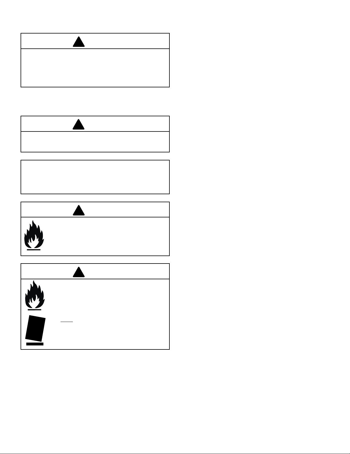
CAUTION
HOT GLASS WILL CAUSE BURNS.
DO NOT TOUCH GLASS UNTIL
COOLED.
NEVER ALLOW CHILDREN TO
TOUCH GLASS.
A barrier designed to reduce the risk of burns from the
hot viewing glass is provided with this appliance and shall
be installed for the protection of children and other at-risk
individuals.
WARNING: If the information in these
instructions is not followed exactly, a fire or
explosion may result causing property damage,
personal injury, or death.
- DO NOT store or use gasoline or other ammable
vapors and liquids in the vicinity of this or any other
appliance.
- What to do if you smell gas
• DO NOT try to light any appliance.
• DO NOT touch any electrical switch; do not use any
phone in your building.
• Immediately call your gas supplier from a neighbor’s
phone. Follow the gas supplier’s instructions.
• If you cannot reach your gas supplier, call the re
department.
- Installation and service must be performed by a qualied
installer, service agency, or the gas supplier.
Installation and service of this appliance should be
performed by qualied personnel. Hearth & Home
Technologies suggests NFI certied or factory trained
professionals, or technicians supervised by an NFI
certied professional.
Installation and service of this appliance should be performed by
qualied personnel. Hearth & Home Technologies recommends
HHT Factory Trained or NFI certied professionals.
Heat & Glo • PALOMA-BZ-MOD, PALOMA-GR-MOD, PALOMA-GY-MOD • 2189-900_R25 • 05/201
This appliance may be installed as an OEM installation in
manufactured home (USA only) or mobile home and must be
installed in accordance with the manufacturer’s instructions and
the manufactured home construction and safety standard, Title
24 CFR, Part 3280 or Standard for Installation in Mobile Homes,
CAN/CSA Z240MH.
This appliance is only for use with the type(s) of gas indicated
on the rating plate.
Page 2
Read this manual before installing or operating this appliance.
Please retain this owner’s manual for future reference.
Congratulations
Congratulations on selecting a Heat & Glo gas appliance an
elegant and clean alternative to wood burning appliances.
The Heat & Glo gas appliance you have selected is designed
to provide the utmost in safety, reliability, and eciency.
As the owner of a new appliance, you’ll want to read and
carefully follow all of the instructions contained in this Owner’s
The information contained in this Owner’s Manual, unless
noted otherwise, applies to all models and gas control
systems.
Your new Heat & Glo gas appliance will give you years of
durable use and trouble-free enjoyment. Welcome to the
Heat & Glo family of appliance products!
Manual. Pay special attention to all Cautions and Warnings.
This Owner’s Manual should be retained for future reference.
We suggest that you keep it with your other important
documents and product manuals.
Homeowner Reference Information
We recommend that you record the following pertinent
information about your appliance.
Model Name: ___________________________________________ Date purchased/installed: __________________
Serial Number: __________________________________________ Location on appliance: ____________________
Dealership purchased from: _______________________________ Dealer Phone: __________________________
Notes: _______________________________________________________________________________________
_____________________________________________________________________________________________
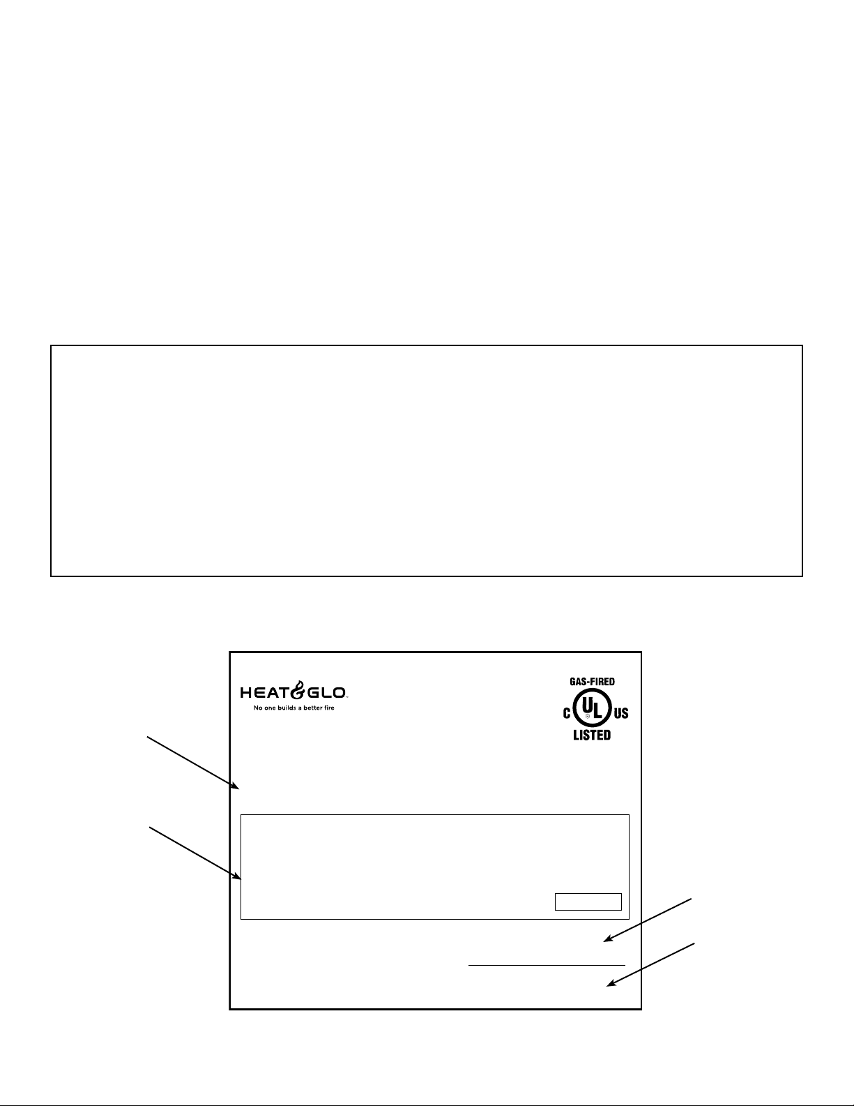
Listing Label Information/Location
Type of Gas
Gas and Electric
Information
Not Not for for use use with with solid solid fuel.fuel.
((Ne Ne doit doit pas pas entre entre utilise utilise avec avec un un combustible combustible solide).solide).
Type Type of of Gas Gas (Sorte (Sorte De De Gaz)Gaz)::
NNAATURALTURAL GASGAS
Minimum Minimum Permissible Permissible Gas Gas Supply Supply for for Purposes Purposes of of Input Input Adjustment.Adjustment.
Approved Approved Minimum Minimum (De (De Gaz) Gaz) AcceptableAcceptable 0.00.0 in in w.c.w.c. (Po. (Po. Col. Col. d’eau)d’eau)
Maximum Maximum Pressure Pressure (Pression)(Pression) 0.00.0 in in w.c.w.c. (Po. (Po. Col. Col. d’eau)d’eau)
Maximum Maximum Manifold Manifold Pressure Pressure (Pression)(Pression) 0.00.0 in in w.c.w.c. (Po. (Po. Col. Col. d’eau)d’eau)
Minimum Minimum Manifold Manifold Pressure Pressure (Pression)(Pression) 0.00.0 in in w.c.w.c. (Po. (Po. Col. Col. d’eau)d’eau)
Total Total Electrical Electrical Requirements: Requirements: 000Vac, 000Vac, 00Hz., 00Hz., less less than than 00 00 AmperesAmperes
ALTITUDE:ALTITUDE: 0-0000 0-0000 FT.FT. 0000-0000FT.0000-0000FT.
MAX. MAX. INPUT INPUT BTUH:BTUH: 00,00000,000 00,00000,000
MIN. MIN. INPUT INPUT BTUH:BTUH: 00,00000,000 00,00000,000
ORIFICE ORIFICE SIZE:SIZE: #XXXXX#XXXXX #XXXXX#XXXXX
The model information regarding your specic appliance can be found on
the rating plate usually located in the control area of the appliance.
Heat & Glo, a brand of Hearth & Home Technologies
7571 215th Street West, Lakeville, MN 55044
This This appliance appliance must must be be installed installed in in accordance accordance with with local local codes, codes, if if any; any; if if not, not, follow follow ANSI ANSI Z223.1Z223.1
in in the the USA USA or or CAN/CGA CAN/CGA B149 B149 installation installation codes. codes. (Installer (Installer l’appareil l’appareil selon selon les les codes codes ou ou reglementsreglements
locaux locaux ou, ou, en en l’absence l’absence de de tels tels reglements, reglements, selon selon les les codes codes d’installation d’installation CAN/CGA-B149.)CAN/CGA-B149.)
ANSI ANSI Z21XX-XXXX Z21XX-XXXX · · CSA CSA 2.XX-MXX 2.XX-MXX
IN IN CANADACANADA
Model:Model:
(Modele):(Modele):
SerialSerial
(Serie):(Serie):
MADE MADE IN IN USAUSA
XXXXXXXXXXXXXXXX
XXXXXXXXXXXXXXXX
Model Number
Serial Number
Heat & Glo • PALOMA-BZ-MOD, PALOMA-GR-MOD, PALOMA-GY-MOD • 2189-900_R25 • 05/202
Page 3

Table of Contents
1 Listing and Code Approvals
A. Appliance Certication ............................ 4
B. Glass Specications .............................. 4
C. BTU Specications ............................... 4
D. High Altitude Installations .......................... 4
E. Non-Combustible Materials Specication. . . . . . . . . . . . . . 4
F. Combustible Materials Specication ................. 4
G. Electrical Codes ................................. 4
H. Requirements for the Commonwealth of Massachusetts .. 5
I. California Safety Information ....................... 5
2 Getting Started
A. Design and Installation Considerations ............... 6
B. Tools and Supplies Needed ........................ 6
C. Inspect Appliance and Components .................. 6
3 Framing and Clearances
A. Selecting Appliance Location ....................... 7
B. Clearances to Combustibles ....................... 8
4 Termination Locations
A. Vent Termination Minimum Clearances ............... 9
5 Vent Information
A. Venting Components .............................11
B. Use of Elbows ..................................11
C. Measuring Standards .............................11
D. How to Use the Vent Graph ....................... 12
E. Venting Guidelines .............................. 12
F. Horizontal Termination ........................... 13
G. Vertical Termination ............................. 15
H. Secure the Vent Sections ......................... 18
I. Disassemble Vent Sections ....................... 18
J. Cathedral Ceiling ............................... 19
K. Class A Metal Chimney .......................... 20
L. Existing Masonry Chimney ........................ 21
6 Gas Information
A. Fuel Conversion ................................ 25
B. Gas Pressures ................................. 25
C. Gas Connection ................................ 26
8 Appliance Setup
A. Remove Shipping Materials ....................... 30
B. Unbolting Appliance from the Pallet ................. 30
C. Leveling and Lagging Down the Appliance ........... 30
D. Accessories ................................... 31
E. Top to Rear Vent Conversion ...................... 31
F. Shutter Adjustment .............................. 32
G. Installing the Vent Restrictor. . . . . . . . . . . . . . . . . . . . . . . 33
H. Installing Rock Media and Ember Material ............ 33
I. Optional Blower ................................ 35
J. Remote Controls ............................... 38
K. Front Door Glass Assembly Replacement ............ 40
L. Inner Glass Door Assembly Replacement ............ 40
9 Operating Instructions
A. Before Lighting Appliance. . . . . . . . . . . . . . . . . . . . . . . . . 41
B. Controls ...................................... 41
C. Lighting Instructions (IPI) ......................... 42
D. After Appliance is Lit ............................. 43
E. Frequently Asked Questions ...................... 43
10 Troubleshooting
A. IntelliFire Ignition System ......................... 44
11 Maintaining and Servicing Appliance
A. Maintenance Tasks .............................. 47
12 Reference Materials
A. Appliance Dimension Diagram ..................... 48
B. Vent Components Diagram ....................... 49
C. Vent Components List ........................... 51
D. Service Parts .................................. 52
E. Limited Lifetime Warranty ......................... 56
F. Contact Information ............................. 58
= Contains updated information.
7 Electrical Information
A. Recommendation for Wire ........................ 27
B. Connecting to the Appliance. . . . . . . . . . . . . . . . . . . . . . . 27
C. IntelliFire
D. Loss of Power and Battery Backup Usage ............ 28
E. Wall Switch Installation for Fan (Optional) ............ 29
®
Ignition System Wiring .................. 27
Heat & Glo • PALOMA-BZ-MOD, PALOMA-GR-MOD, PALOMA-GY-MOD • 2189-900_R25 • 05/203
Page 4
1 1
Listing and Code Approvals
A. ApplianceCertication
Models:
Laboratory: Underwriters Laboratories, Inc. (UL)
Type: Vented Gas Fireplace Heater
Standard: ANSI Z21.88-2019/CSA 2.33-2019
This product is listed to ANSI standards for “Vented Gas
Appliance Heaters” and applicable sections of “Gas
Burning Heating Appliances for Manufactured Homes and
Recreational Vehicles”, and “Gas Fired Appliances for Use
at High Altitudes”.
NOT INTENDED FOR USE AS A PRIMARY HEAT SOURCE.
This appliance is tested and approved as either supplemental
room heat or as a decorative appliance. It should not be
factored as primary heat in residential heating calculations.
Manufactured Home or Mobile Home installation may occur
only after the home is site located and must conform with
the Manufactured Home Construction and Safety Standard,
Title 24 CFR, Part 3280, or, when such a standard is
not applicable, the Standard for Manufactured Home
Installations, ANSI/NCSBCS A225.1, or Standard for Gas
Equipped Recreational Vehicles and Mobile Housing, CSA
Z240.4.
When installed, the appliance must be electrically grounded
in accordance with local codes or, in the absence of local
codes, with the National Electrical Code, ANSI/NFPA 70, or
the Canadian Electrical Code, CSA C22.1.
Paloma-BZ-MOD, Paloma-BK-MOD,
Paloma-GY-MOD
B. GlassSpecications
This appliance is equipped with 5 mm ceramic glass behind
the curved glass. Replace glass only with 5 mm ceramic
glass. Please contact your dealer for replacement glass.
Note: This installation must conform with local codes. In the
absence of local codes you must comply with the National Fuel
Gas Code, ANSI Z223.1-latest edition in the U.S.A. and the
CAN/CGA B149 Installation Codes in Canada.
C. BTUSpecications
Model
(US or Canada)
Paloma
Natural Gas
Paloma
Propane
Maximum
Input
BTU/h
28,000 20,000 38 81 71
26,000 19,000 53 81 72
Minimum
Input
BTU/h
Orice
Size
(DMS)
*Steady
State
Eciency%
**P.4
%
D. High Altitude Installations
Omni-Test Laboratories, Inc. listed gas appliances are tested
and approved without requiring changes for elevations from
0 to 2000 feet in the U.S.A. and 0 to 4500 feet in Canada.
When installing this appliance at an elevation above 2000
feet, it may be necessary to decrease the input rating by
changing the existing burner orice to a smaller size. Input
rate should be reduced by 4% for each 1000 feet above a
2000 foot elevation in the U.S.A. If the heating value of the
gas has been reduced, these rules do not apply. To identify
the proper orice size, check with the local gas utility.
If installing this appliance at an elevation above 4500 feet
(in Canada), check with local authorities.
WARNING! Risk of Fire, Explosion or Electric Shock! DO
NOT use this appliance if any part has been under water.
Call a qualied service technician to inspect the appliance
and to replace any part of the control system and/or gas
control which has been under water.
E. Non-CombustibleMaterialsSpecication
Material which will not ignite and burn. Such materials are
those consisting entirely of steel, iron, brick, tile, concrete,
slate, glass or plasters, or any combination thereof.
Materials that are reported as passing ASTM E 136,
Standard Test Method for Behavior of Materials in a
Vertical Tube Furnace at 750ºC, shall be considered non-
combustible materials.
F. CombustibleMaterialsSpecication
Materials made of or surfaced with wood, compressed
paper, plant bers, plastics, or other material that can
ignite and burn, whether ame proofed or not, or whether
plastered or unplastered shall be considered combustible
materials.
G. Electrical Codes
NOTICE: This appliance must be electrically wired and
grounded in accordance with local codes or, in the absence
of local codes, with National Electric Code ANSI/NFPA
70-latest edition or the Canadian Electric Code CSA
C22.1.
• A 110-120 VAC circuit for this product must be protected with
ground-fault circuit-interrupter protection, in compliance with
the applicable electrical codes, when it is installed in locations
such as in bathrooms or near sinks.
*Maximum Vent Blower On
**Canada Only
Heat & Glo • PALOMA-BZ-MOD, PALOMA-GR-MOD, PALOMA-GY-MOD • 2189-900_R25 • 05/204
Page 5
Note: The following requirements reference various
Massachusetts and national codes not contained in this
document.
H. Requirements for the Commonwealth of
Massachusetts
For all side wall horizontally vented gas fueled equipment
installed in every dwelling, building or structure used in
whole or in part for residential purposes, including those
owned or operated by the Commonwealth and where
the side wall exhaust vent termination is less than seven
(7) feet above nished grade in the area of the venting,
including but not limited to decks and porches, the following
requirements shall be satised:
Installation of Carbon Monoxide Detectors
At the time of installation of the side wall horizontal vented
gas fueled equipment, the installing plumber or gas tter
shall observe that a hard wired carbon monoxide detector
with an alarm and battery back-up is installed on the
oor level where the gas equipment is to be installed. In
addition, the installing plumber or gas tter shall observe
that a battery operated or hard wired carbon monoxide
detector with an alarm is installed on each additional level
of the dwelling, building or structure served by the side
wall horizontal vented gas fueled equipment. It shall be the
responsibility of the property owner to secure the services
of qualied licensed professionals for the installation of hard
wired carbon monoxide detectors.
In the event that the side wall horizontally vented gas fueled
equipment is installed in a crawl space or an attic, the hard
wired carbon monoxide detector with alarm and battery
back-up may be installed on the next adjacent oor level.
In the event that the requirements of this subdivision can not
be met at the time of completion of installation, the owner
shall have a period of thirty (30) days to comply with the
above requirements; provided, however, that during said
thirty (30) day period, a battery operated carbon monoxide
detector with an alarm shall be installed.
Approved Carbon Monoxide Detectors
Each carbon monoxide detector as required in accordance
with the above provisions shall comply with NFPA 720 and
be ANSI/UL 2034 listed and IAS certied.
Signage
A metal or plastic identication plate shall be permanently
mounted to the exterior of the building at a minimum height
of eight (8) feet above grade directly in line with the exhaust
vent terminal for the horizontally vented gas fueled heating
appliance or equipment. The sign shall read, in print size no
less than one-half (1/2) inch in size, “GAS VENT DIRECTLY
BELOW. KEEP CLEAR OF ALL OBSTRUCTIONS”.
Inspection
The state or local gas inspector of the side wall horizontally
vented gas fueled equipment shall not approve the
installation unless, upon inspection, the inspector observes
carbon monoxide detectors and signage installed in
accordance with the provisions of 248 CMR 5.08(2)(a)1
through 4.
Exemptions
The following equipment is exempt from 248 CMR 5.08(2)
(a)1 through 4:
• The equipment listed in Chapter 10 entitled “Equipment
Not Required To Be Vented” in the most current edition
of NFPA 54 as adopted by the Board; and
• Product Approved side wall horizontally vented gas fueled
equipment installed in a room or structure separate from
the dwelling, building or structure used in whole or in part
for residential purposes.
Manufacturer Requirements
Gas Equipment Venting System Provided
When the manufacturer of Product Approved side wall
horizontally vented gas equipment provides a venting
system design or venting system components with the
equipment, the instructions provided by the manufacturer
for installation of the equipment and the venting system
shall include:
• Detailed instructions for the installation of the venting
system design or the venting system components; and
• A complete parts list for the venting system design or
venting system.
Gas Equipment Venting System NOT Provided
When the manufacturer of a Product Approved side wall
horizontally vented gas fueled equipment does not provide
the parts for venting the ue gases, but identies “special
venting systems”, the following requirements shall be
satised by the manufacturer:
• The referenced “special venting system” instructions shall
be included with the appliance or equipment installation
instructions; and
• The “special venting systems” shall be Product Approved
by the Board, and the instructions for that system shall
include a parts list and detailed installation instructions.
A copy of all installation instructions for all Product Approved
side wall horizontally vented gas fueled equipment, all
venting instructions, all parts lists for venting instructions,
and/or all venting design instructions shall remain with the
appliance or equipment at the completion of the installation.
See Gas Connection section for additional
Commonwealth of Massachusetts requirements.
I. California Safety Information
WARNING
!
This product and the fuels used to operate this product
(liquid propane or natural gas), and the products of
combustion of such fuels, can expose you to chemicals
including benzene, which is known to the State of
California to cause cancer and reproductive harm. For
more information go to: www.P65Warnings.ca.gov.
Heat & Glo • PALOMA-BZ-MOD, PALOMA-GR-MOD, PALOMA-GY-MOD • 2189-900_R25 • 05/205
Page 6
2 2
!
!
!
Getting Started
A. Design and Installation Considerations
Heat & Glo direct vent gas appliances are designed to
operate with all combustion air siphoned from outside of the
building and all exhaust gases expelled to the outside. No
additional outside air source is required.
CAUTION
Check building codes prior to installation.
• Installation MUST comply with local, regional, state and
national codes and regulations.
• Consult local building, re ocials or authorities having
jurisdiction about restrictions, installation inspection, and
permits.
When planning an appliance installation, it’s necessary to
determine the following information before installing:
• Where the appliance is to be installed.
• The vent system conguration to be used.
• Gas supply piping.
• Electrical wiring.
• Framing and nishing details.
• Whether optional accessories—devices such as a fan, wall
switch, or remote control—are desired.
WARNING
Keep appliance dry.
• Mold or rust may cause odors.
• Water may damage controls.
B. Tools and Supplies Needed
Before beginning the installation be sure that the following
tools and building supplies are available.
Reciprocating saw Framing material
Pliers Noncorrosive leak check solution
or combustible gas detector
Hammer Gloves
Phillips screwdriver Framing square
Flat blade screwdriver Electric drill and bits (1/4 in.)
Plumb line Safety glasses
Level Wrenches
Ratchets/Sockets Allen Wrench Set
Manometer Voltmeter
Tape measure 1/2 - 3/4 inch length, #6 or #8 Self-
drilling screws
One 1/4 inch female connection (for optional fan)
Caulk with a minimum of 300ºF continuous exposure rating
C. Inspect Appliance and Components
• Carefully remove the appliance and components from the
packaging.
• The vent system components and decorative doors and
fronts may be shipped in separate packages.
• If packaged separately, the rock set must be installed.
• Report to your dealer any parts damaged in shipment,
particularly the condition of the glass.
• Read all of the instructions before starting the
installation. Follow these instructions carefully during
theinstallationtoensuremaximumsafetyandbenet.
WARNING
RISK OF FIRE OR EXPLOSION! Damaged parts
could impair safe operation. DO NOT install damaged,
incomplete or substitute components. Keep appliance
dry.
Hearth & Home Technologies disclaims any responsibility
for, and the warranty will be voided by, the following
actions:
• Installation and use of any damaged appliance or vent
system component.
• Modication of the appliance or vent system.
• Installation other than as instructed by Hearth & Home
Technologies.
• Improper positioning of the rock set or the glass door.
• Installation and/or use of any component part not
approved by Hearth & Home Technologies.
Anysuchactionmaycausearehazard.
Installation and service of this appliance should be performed by
qualied personnel. Hearth & Home Technologies recommends
HHT Factory Trained or NFI certied professionals.
Heat & Glo • PALOMA-BZ-MOD, PALOMA-GR-MOD, PALOMA-GY-MOD • 2189-900_R25 • 05/206
Page 7
3 3
Framing and Clearances
Note:
• Illustrations reect typical installations and are FOR
DESIGN PURPOSES ONLY.
• Illustrations/diagrams are not drawn to scale.
• Actual installation may vary due to individual design
preference.
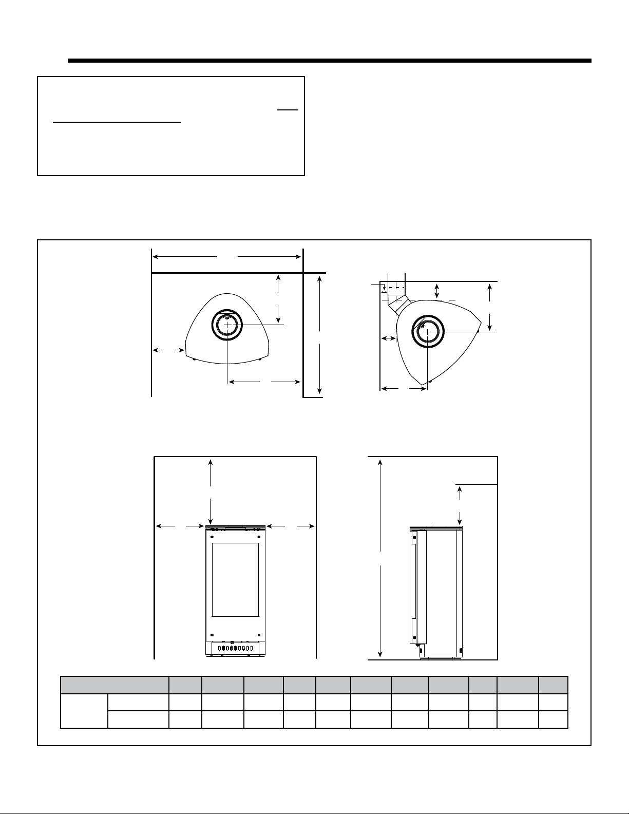
A. Selecting Appliance Location
When selecting a location for your appliance it is important
to consider the required clearances to walls (see gure 3.1).
F
B
E
A
J
“A” MEASUREMENT IS FROM APPLIANCE TOP, NOT SIDE
ALCOVE
G
A
A
I
K
C
K
C
H
D
Paloma
Figure 3.1
Model A B C D E F G H I J K
Inches 6 10-1/8 12-1/8 54 36 30-3/4 13-1/4 13-1/4 1 15-1/2 5
Millimeters 152 257 308 1372 914 781 337 337 25 394 127
Heat & Glo • PALOMA-BZ-MOD, PALOMA-GR-MOD, PALOMA-GY-MOD • 2189-900_R25 • 05/207
Page 8
B. Clearances to Combustibles
!
!
!
!
WARNING
RISK OF FIRE OR BURNS! Provide adequate
clearance around air openings and for service
access. Due to high temperatures, the appliance should
be located out of trac and away from furniture and
draperies.
NOTE: For actual appliance dimensions refer to Section 12.
It is permissible to place the appliance on carpet.
CAUTION
Some carpet materials may be sensitive to radiant heat
from the appliance causing discoloration or odor.
Note: Flooring beneath appliance may reach 90 degrees
plus room ambient temperature. Check with flooring
manufacturer for maximum temperature allowed on
flooring surfaces.
WARNING
Fire Risk
• Locate and install appliance to all clearance
specications in manual.
WARNING
Fire Risk, Odor Risk, Tipping Risk
• Install gas stove on a stable, level platform/
oor strong enough to support gas stove
without tipping.
• USE wood flooring, ceramic tile, brick
hearth or high pressure laminate ooring
applied directly over the sub-flooring
material.
Heat & Glo • PALOMA-BZ-MOD, PALOMA-GR-MOD, PALOMA-GY-MOD • 2189-900_R25 • 05/208
Page 9
4 4
HORIZONTAL
A B
!
Termination Locations
A. Vent Termination Minimum Clearances
WARNING
Fire Risk, Explosion Risk
Maintain vent clearance to combustibles as
specied.
• Do not pack air space with insulation or
other materials.
Failure to keep insulation or other materials
away from vent pipe may cause re.
Measure vertical clearances from this surface.
Measure horizontal clearances from this surface.
(SeeFigure4.4forspecicclearances)
Figure 4.1
OVERHANG
2 FT.
MIN.
GAS DIRECT VENT
TERMINATION CAP
20 INCHES MIN.
LOWEST
DISCHARGE
OPENING
H (MIN.) - MINIMUM HEIGHT FROM ROOF
TO LOWEST DISCHARGE OPENING
X
12
ROOF PITCH
VERTICAL
WALL
IS X/ 12
Roof Pitch H (Min.) Ft.
Flat to 6/12...........................................................1.0*
Over 6/12 to 7/12 .................................................1.25*
Over 7/12 to 8/12 .................................................1.5*
Over 8/12 to 9/12 .................................................2.0*
Over 9/12 to 10/12 ...............................................2.5*
Over 10/12 to 11/12 .............................................3.25
Over 11/12 to 12/12 .............................................4.0
Over 12/12 to 14/12 .............................................5.0
Over 14/12 to 16/12 .............................................6.0
Over 16/12 to 18/12 .............................................7.0
Over 18/12 to 20/12 .............................................7.5
Over 20/12 to 21/12 .............................................8.0
* 3 foot minimum in snow regions
Figure 4.2 - Minimum height from roof to lowest discharge opening
Figure 4.2 species minimum vent heights for various
pitched roofs.
6 in. (minimum) up to 20 in.
152 mm/508 mm
20 in. and over 0 in. minimum
18 in. minimum
457 mm
Gas, Wood or Fuel Oil
Termination Cap
B
A *
Gas
Termination
Cap **
If using decorative cap cover(s), this distance may need to be
*
increased. Refer to the installation instructions supplied with the
decorative cap cover.
In a staggered installation with both gas and wood or fuel oil
**
terminations, the wood or fuel oil termination cap must be
higher than the gas termination cap.
Figure 4.3 - Staggered Termination Caps
Heat & Glo • PALOMA-BZ-MOD, PALOMA-GR-MOD, PALOMA-GY-MOD • 2189-900_R25 • 05/209
Page 10
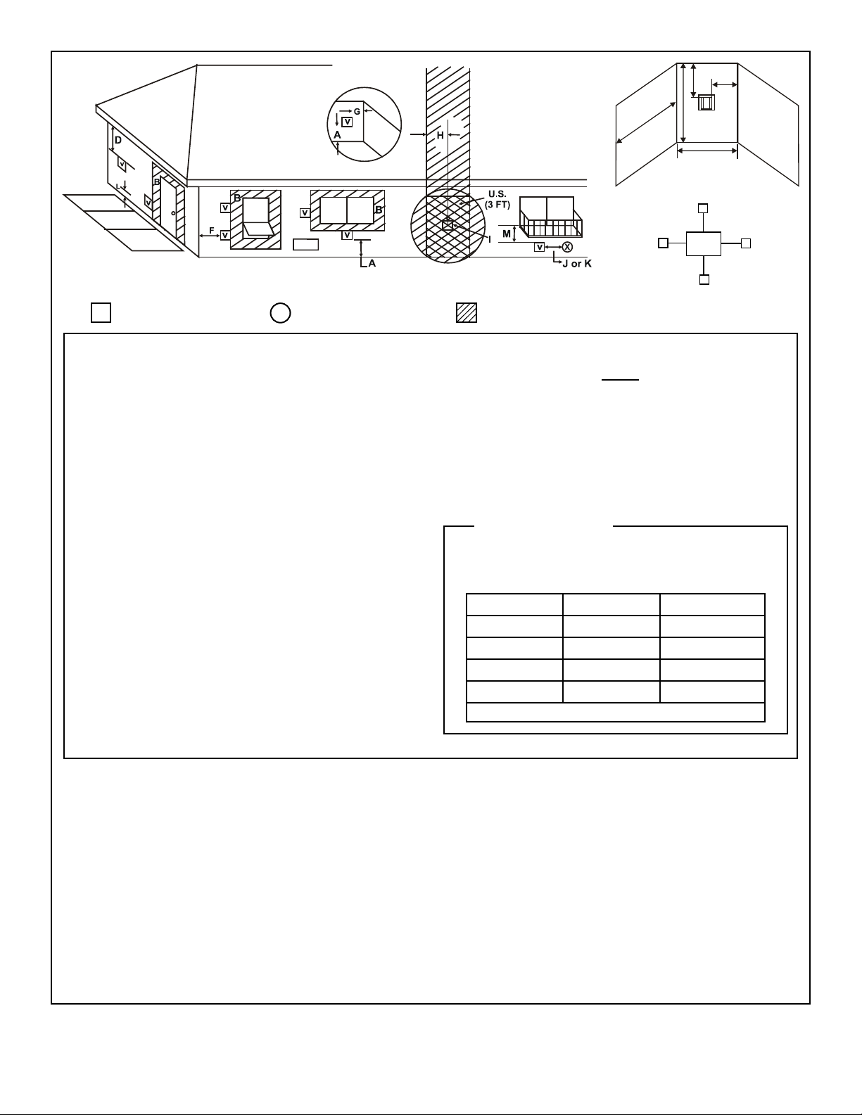
V
M
P
R
Q
(See Note 2)
V
T
S
Electrical
V
Service
D*
V
= VENT TERMINAL = AREA WHERE TERMINAL IS NOT PERMITTED
V
= AIR SUPPLY INLET
X
N
S
V
A = 12 inches.................clearances above grade, veranda,
(See Note 1)
porch, deck or balcony
B = 12 inches.................clearances to window or door that
may be opened, or to permanently
closed window. (Glass)
D* = 18 inches.................vertical clearance to unventilated
sot or to ventilated sot located
above the terminal
*30 inches ...................for vinyl clad soffits and below
electrical service
F = 9 inches..................clearance to outside corner
G = 6 inches...................clearance to inside corner
H = 3 ft. (Canada) ..........not to be installed above a gas meter/
regulator assembly within 3 feet (90
cm) horizontally from the center-line
of the regulator
I = 3 ft ...........................clearance to gas service regulator
vent outlet
J = 9 inches (U.S.A.)
12 inches (Canada) clearance to non-mechanical
air supply inlet to building or the
combustion air inlet to any other
appliance
K = 3 ft. (U.S.A.)
6 ft. (Canada) ...........clearance to a mechanical
(powered) air supply inlet
L** = 7 ft. ......................... clearance above paved sidewalk
(See Note 1)
or a paved driveway located on
public property
M*** = 18 inches................ clearance under veranda, porch, dec k,
balcony or overhang
42 inches ............... vinyl
S = 6 inches................. clearance from sides of electrical
(See Note 5)
service
T = 12 inches................ clearance above electrical service
(See Note 5)
Alcove Applications
N = 6 inches ..................non-vinyl sidewalls
12 inches ................vinyl sidewalls
P = 8 ft.
Q
MIN
1 cap 3 feet 2 x Q
2 caps 6 feet 1 x Q
3 caps 9 feet 2/3 x Q
4 caps 12 feet 1/2 x Q
Q
= # termination caps x 3 R
MIN
= (2 / # termination caps) x Q
MAX
R
MAX
ACTUAL
ACTUAL
ACTUAL
ACTUAL
ACTUAL
** a vent shall not terminate directly above a sidewalk or paved driveway
which is located between two single family dwellings and serves both
dwellings.
*** only permitted if veranda, porch, deck or balcony is fully open on a
minimum of 2 sides beneath the oor, or meets Note 2.
NOTE 1: On private property where termination is less than 7 feet above
a sidewalk, driveway, deck, porch, veranda or balcony, use of a listed cap
shield is suggested. (See vents components page)
NOTE 2: Termination in an alcove space (spaces open only on one side
and with an overhang) are permitted with the dimensions specied for
vinyl or non-vinyl siding and sots. 1. There must be 3 feet minimum
between termination caps. 2. All mechanical air intakes within 10 feet
of a termination cap must be a minimum of 3 feet below the termination
cap. 3. All gravity air intakes within 3 feet of a termination cap must be a
minimum of 1 foot below the termination cap.
NOTE 3: Local codes or regulations may require dierent clearances.
NOTE 4: Termination caps may be hot. Consider their proximity to doors
or other trac areas.
NOTE 5: Location of the vent termination must not interfere with access
to the electrical service.
WARNING: In the U.S: Vent system termination is NOT permitted in
screened porches. You must follow side wall, overhang and ground
clearances as stated in the instructions.
In Canada: Vent system termination is NOT permitted in screened
porches. Vent system termination is permitted in porch areas with two or
more sides open. You must follow all side walls, overhang and ground
clearances as stated in the instructions.
Heat & Glo assumes no responsibility for the improper performance of the
appliance when the venting system does not meet these requirements.
Figure 4.4 - Minimum Clearances for Termination
CAUTION: IF EXTERIOR WALLS ARE FINISHED WITH VINYL SIDING, IT IS SUGGESTED THAT A VINYL PROTECTOR KIT BE
INSTALLED.
Heat & Glo • PALOMA-BZ-MOD, PALOMA-GR-MOD, PALOMA-GY-MOD • 2189-900_R25 • 05/2010
Page 11
5 5
!
!
Vent Information
A. Venting Components
In order to comply with applicable codes and product
warranties, use only Hearth & Home Technologies (HHT)
venting components.
DO NOT USE FIELD-FABRICATED VENTING
COMPONENTS. Refer to the venting manufacturer’s
instructions.
This product is approved to be vented either horizontally,
through the side wall or vertically through the roof. You may
vent through a Class A or masonry chimney if an approved
adapter is used.
This appliance is a direct vent heater. All combustion air
must come directly from the outside of the building. The
vent pipe for this unit consists of an inner and an outer pipe.
The inner pipe carries the appliance exhaust out of the
system, and the outer pipe brings fresh combustion air into
the appliance.
• A round support box/wall thimble or heat shield is required
when the venting passes through a combustible wall.
• A support box or ceiling restop is required when the
venting passes through a ceiling.
• Roof ashing and a storm collar are required when venting
passes through the roof.
• Follow instructions provided with the venting for installation
of these items.
B. Use of Elbows
CAUTION
ALL vent conguration specications MUST be followed.
• This product is tested and listed to these specications.
• Appliance performance will suer if specications are
not followed.
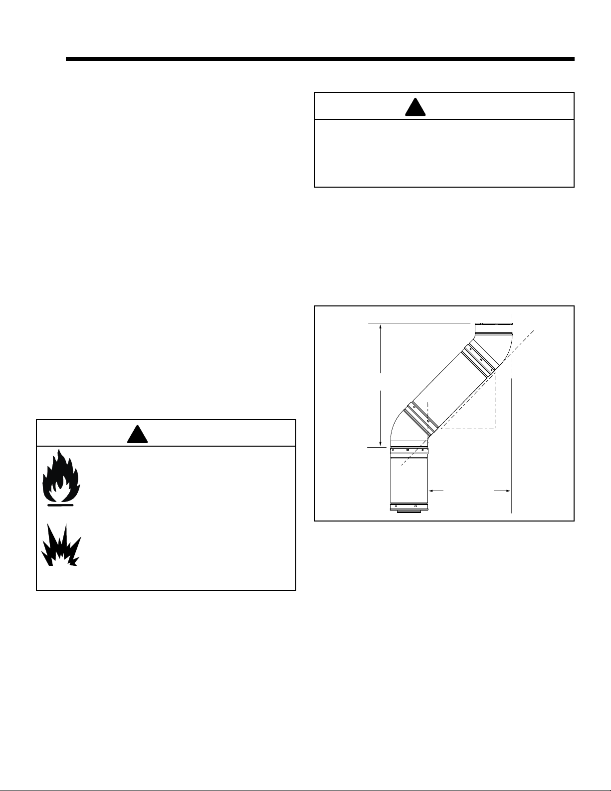
Diagonal runs have both vertical and horizontal vent aspects
when calculating the eects. Use the rise for the vertical
aspect and the run for the horizontal aspect (see Figure 5.1).
Two 45º elbows may be used in place of one 90º elbow. On
45º runs, one foot of diagonal is equal to 8-1/2 (216 mm)
inches horizontal run and 8-1/2 (216 mm) inches vertical run.
A length of straight pipe is allowed between two 45º elbows
(see Figure 5.1).
Vertical
12 in.
8-1/2 in.
WARNING
Fire Hazard, Explosion Risk,
Asphyxiation Risk.
Do NOT connect this gas appliance to a
chimney ue serving a separate solid-fuel or
gas burning appliance.
• Vent this appliance directly outside.
• Use separate vent system for this appliance.
May impair safe operation of this appliance
or other appliances connected to the ue.
8-1/2 in.
Horizontal
Figure 5.1
C. Measuring Standards
Vertical and horizontal measurements were made using the
following standards.
1. Pipe measurements are from center line to center line.
2. Horizontal terminations are measured to the outside
mounting surface (ange of termination cap) (see Figure
4.1) on page 9.
3. Vertical terminations are measured to the top of the last
pipe before termination cap.
4. Horizontal pipe installed level with 1/4 inch rise per foot.
Heat & Glo • PALOMA-BZ-MOD, PALOMA-GR-MOD, PALOMA-GY-MOD • 2189-900_R25 • 05/2011
Page 12
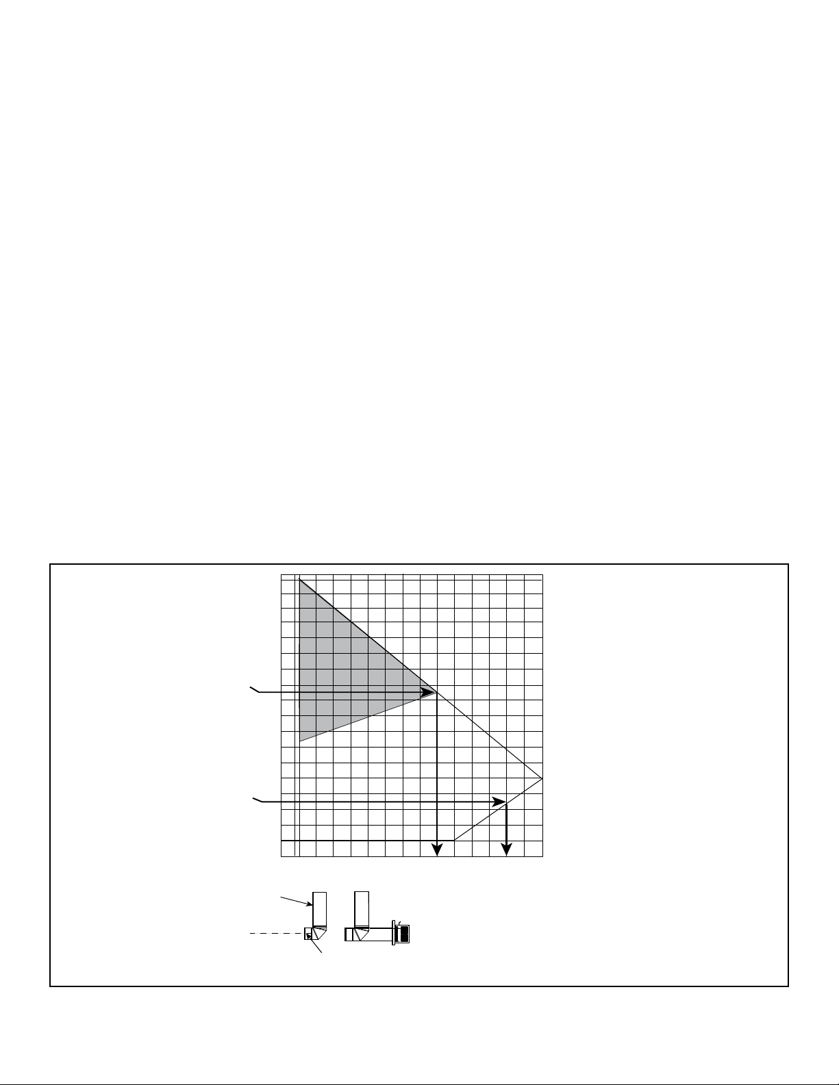
EX. 2
EX. 1
2' 4' 6' 8' 10' 12' 14' 15'
30'
28'
26'
24'
22'
20'
18'
16'
14'
12'
10'
8'
6'
4'
2'
0'
(MAX)
(MIN)
32'
34'
35'
11-5/8”
2 ft. (610 mm) Maximum Horizontal run with no
vertical pipe and with 1/4 in. (6 mm) rise per foot.
6 ft. (2 m) Minimum
Vertical Termination
For rear vent or top
of appliance for top
vent.
C
L
6 in. (152 mm) Minimum starter pipe
C
L
VERTICAL DISTANCE
FROM APPLIANCE
TO THE 90º ELBOW
TOTAL HORIZONTAL RUN TO
OUTSIDE OF EXTERIOR WALL
(INCLUDING ELBOWS)
To adjust the vent restrictor
plate, see page 34.
VENT RESTRICTOR
PLATE REQUIRED
D. How to Use the Vent Graph
1. Measure the distance from the top of appliance to the
center of the 90° elbow. On the graph below, draw a
horizontal line from that measurement on the vertical
axis across until it intersects with the slanted line.
2. From the point of this intersection, draw a vertical line to
the bottom of the graph.
3. The point at which this line meets the bottom line of the
graph is the maximum length of the horizontal run.
Example 1: If the vertical dimension from the top of the
appliance to the center of the 90° elbow is 7 ft. (2 m), the
horizontal run to the outer wall ange must not exceed 13
ft. (4 m).
Example 2: If the vertical dimension from the top of the
appliance is 21 ft. (6.4 m), the horizontal run to the outer
wall ange must not exceed 9 ft. (3 m).
4. Each 90° elbow is equivalent to 3 ft. (914 mm) of vent
pipe and each 45° elbow is equivalent to 1 ft. (305 mm)
of vent pipe, and must be subtracted from vent pipe
run. A single vertical to horizontal 90° elbow is already
calculated into the allowable 15 ft. (5 m) run. Each
additional 90° elbow reduces the maximum horizontal
distance by 3 ft. (914 mm).
Example: The use of three elbows would reduce the
allowable horizontal run to 9 ft. (3 - 1 = 2 elbows x 3 ft. =
6 ft.; 15 ft. max. - 6 ft. = 9 ft. max.)
E. Venting Guidelines
• Minimum 2 ft. vertical rise for top vent installations before
first elbow.
• The maximum horizontal vent run is 15 ft. (5 m) when the
vertical vent rise is 10 ft. (3 m).
• The minimum horizontal vent run is 11-5/8 in. (295 mm).
• Horizontal sections require a 1/4 in. (6 mm) rise for every
12 in. (305 mm) of horizontal travel.
•
Horizontal sections require noncombustible support every
3 ft. (914 mm), e.g. wall strap.
• Wall thickness: Minimum 4 in. (102 mm). Maximum 20 in.
(508 mm).
• Vent Diameter: Exterior 6-5/8 in. (168 mm); Inner 4 in.
(102 mm).
EXCEPTION FOR REAR VENT KIT
INSTALLATION:
• The maximum horizontal vent run is 2 ft. (610 mm).
NOTICE: Maximum horizontal vent run is 18 in. (457 mm)
when using the HRC termination cap.
• The maximum horizontal vent run with a 45° elbow is 18
in. (457 mm).
•
No external minimum rise is required. The minimum
horizontal vent run is 11-5/8 in. (295 mm).
• For any vertical rise when rear venting, a minimum of 2
ft. (610 mm) vertical must be used prior to any horizontal
run.
, HORIZONTAL
Figure 5.2
Heat & Glo • PALOMA-BZ-MOD, PALOMA-GR-MOD, PALOMA-GY-MOD • 2189-900_R25 • 05/2012
Page 13
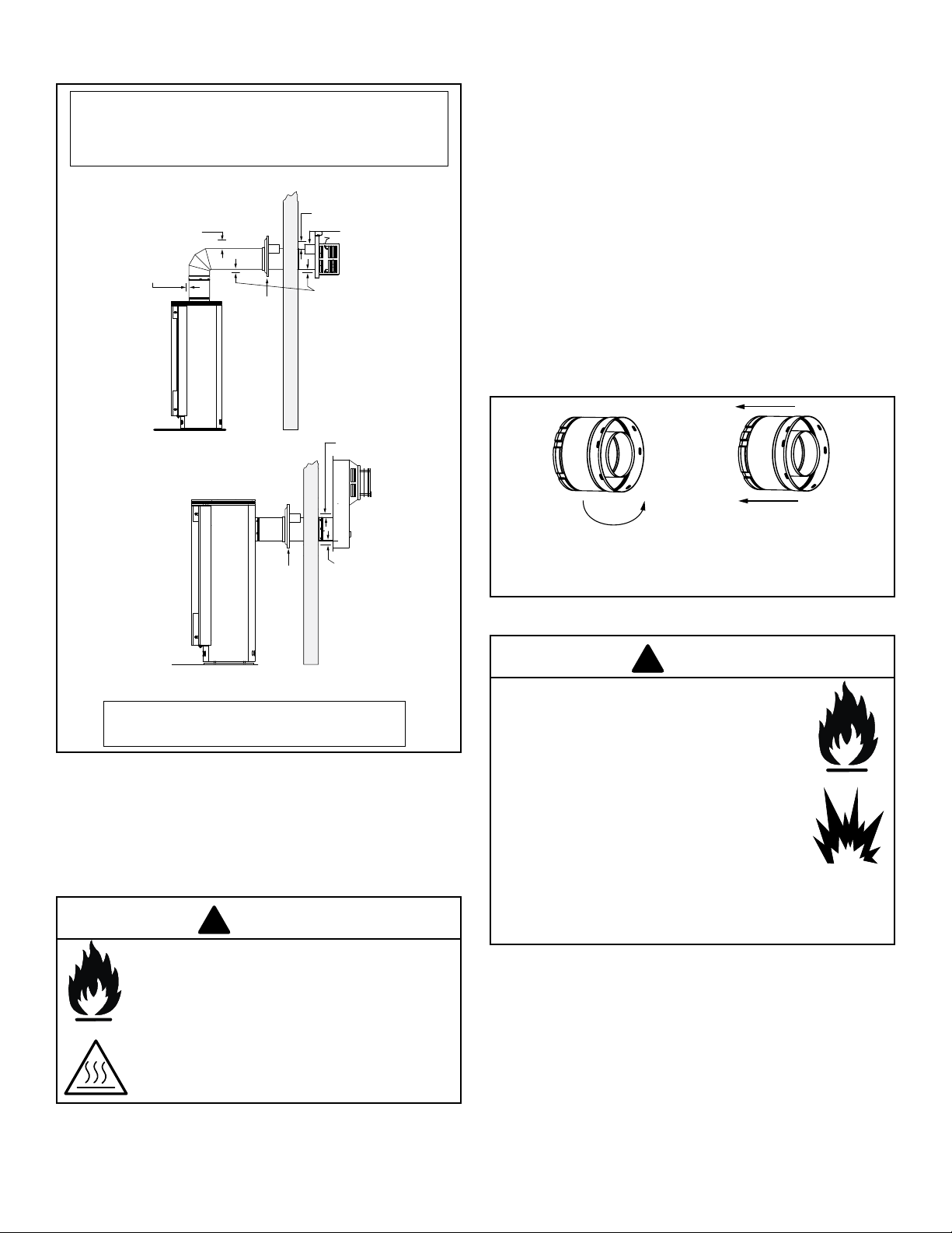
F. Horizontal Termination
!
!
• If wall thickness is less than 4-3/8 the existing heat shields must be field trimmed. If wall
Note: Heat shields MUST overlap by a minimum of 1-1/2 in. (38 mm).
• If wall thickness is less than 4 in. the existing heat shields must be field trimmed. If wall thickness
is greater than 7-1/4 in. a DVP-HSM-B will be required.
• SLP heat shield - designed to be used on a wall 4-3/8 in. to 7-5/8 in. (111 mm to 194 mm thick).
thickness is greater than 7-5/8 in. a DVP-HSM-B will be required.
(SLP Pipe Shown)
3 in. (76 mm)
top clearance
1 in. (25 mm)
clearance around
vertical sections
Wall
Thimble
3 in. (76 mm)
top clearance *
Heat
Shield
1 in. (25 mm)
clearance
bottom & sides
2. Direct vent pipe is designed with a locking connection.
To connect the venting system to the appliance flue
outlet, a twist-lock adapter is built into the appliance
at the factory. Wall thickness may vary. Remember to
include wall thickness in minimum clearances when
figuring venting lengths for your installation needs.
3. Female ends of direct vent pipe/elbows are designed
to slide straight onto the male ends of adjacent pipes
by orienting the pipe indentations so they match and
slide into the entry slots on the male ends, see Figure
5.4. Align the seam of the pipe and seam of collar to
allow engagement. Rotate the vent component to lock
into place. Use this procedure for all vent components.
See Figure 10.5. Continue adding vent components,
locking each succeeding component into place. Ensure
that each succeeding vent component is securely tted
and locked into the preceding component.
WALL
Wall
Thimble
* When using SLP pipe, minimum clearances from the vent pipe to combustible
materials at inside wall firestops are: Top: 2-1/2 in. (64 mm)
Bottom: 1/2 in. (13 mm)
Sides: 1 in. (25 mm)
WALL
3 in. (76 mm)
top clearance *
1 in. (25 mm)
clearance
bottom & sides
Figure 5.3 - Horizontal Venting Clearances To Combustible Materials
1. Determine the desired location of the appliance. Check
to ensure that wall studs or roof rafters are not in the
way when the venting system is being planned. If this
is the case, you may want to adjust the location of the
appliance.
WARNING
Note: Align seams to engage pipe,
then rotate counterclockwise to lock
Figure 5.4 - Adding Venting Components
WARNING
Fire Risk, Explosion Risk, Combustion
Fume Risk.
Use vent run supports per installation
instructions.
Connect vent sections per installation
instructions.
• Maintain all clearances to combustibles.
• Do NOT allow vent to sag below
connection point to appliance.
• Maintain specied slope (if required).
Improper support may allow vent to sag or separate.
Fire Risk, Exhaust Fumes Risk
Impaired Performance of Appliance
• Ensure vent components are locked
together correctly.
• Pipe may separate if not properly joined.
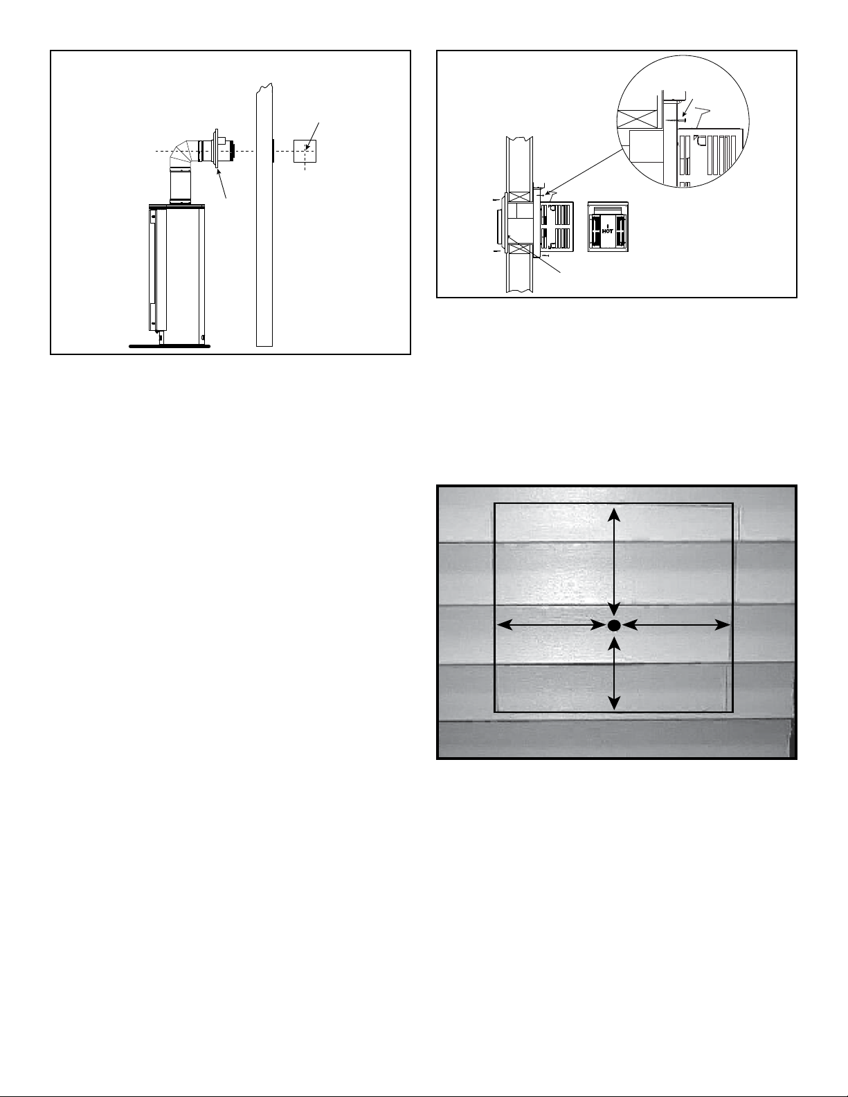
4. For installations using a round support box/wall thimble
(check pipe manufacturer's instructions), mark the wall
for a 10 in. x 10 in. (254 mm x 254 mm) square hole.
The center of the square hole should line up with the
center line of the horizontal pipe, as shown in Figure
5.5. Cut and frame the hole in the exterior wall where
the vent will be terminated. If the wall being penetrated
is constructed of noncombustible material, i.e. masonry
block or concrete, a 7 in. (178 mm) diameter hole is
acceptable.
Heat & Glo • PALOMA-BZ-MOD, PALOMA-GR-MOD, PALOMA-GY-MOD • 2189-900_R25 • 05/2013
Page 14
8 in.
(203 mm)
7 in.
(178 mm)
7 in.
(178 mm)
6 in.
(152 mm)
Centerline
(SLP Pipe Shown)
Wood
Screw
Center of Hole
Centerline
Wall
Thimble
Figure 5.5
5. Installation requires a minimum of 6 in. (152 mm)
horizontal run of vent with a 1/4 in. (6 mm) rise run towards
the termination. Each 1 ft. (305 mm) of horizontal venting
must include a 1/4 in. (6 mm) rise. Never allow the vent
to run downward. This could cause high temperatures
and may present the possibility of a fire. The location of
the horizontal vent termination on an exterior wall must
meet all local and national building codes, and must not
be easily blocked or obstructed, see Figure 4.4 on page
10.
6. For installations requiring a vertical rise on the exterior of
the building, the HHT RHVK snorkel kit (Part #844-8921)
is available with a 14 in. (356 mm) and a 36 in. (914 mm)
tall snorkel termination cap. Follow the same installation
procedures as used for standard horizontal terminations.
If the snorkel termination must be installed below grade
(i.e. basement application), proper drainage must be
provided to prevent water from entering the snorkel
termination. Do not backfill around snorkel termination.
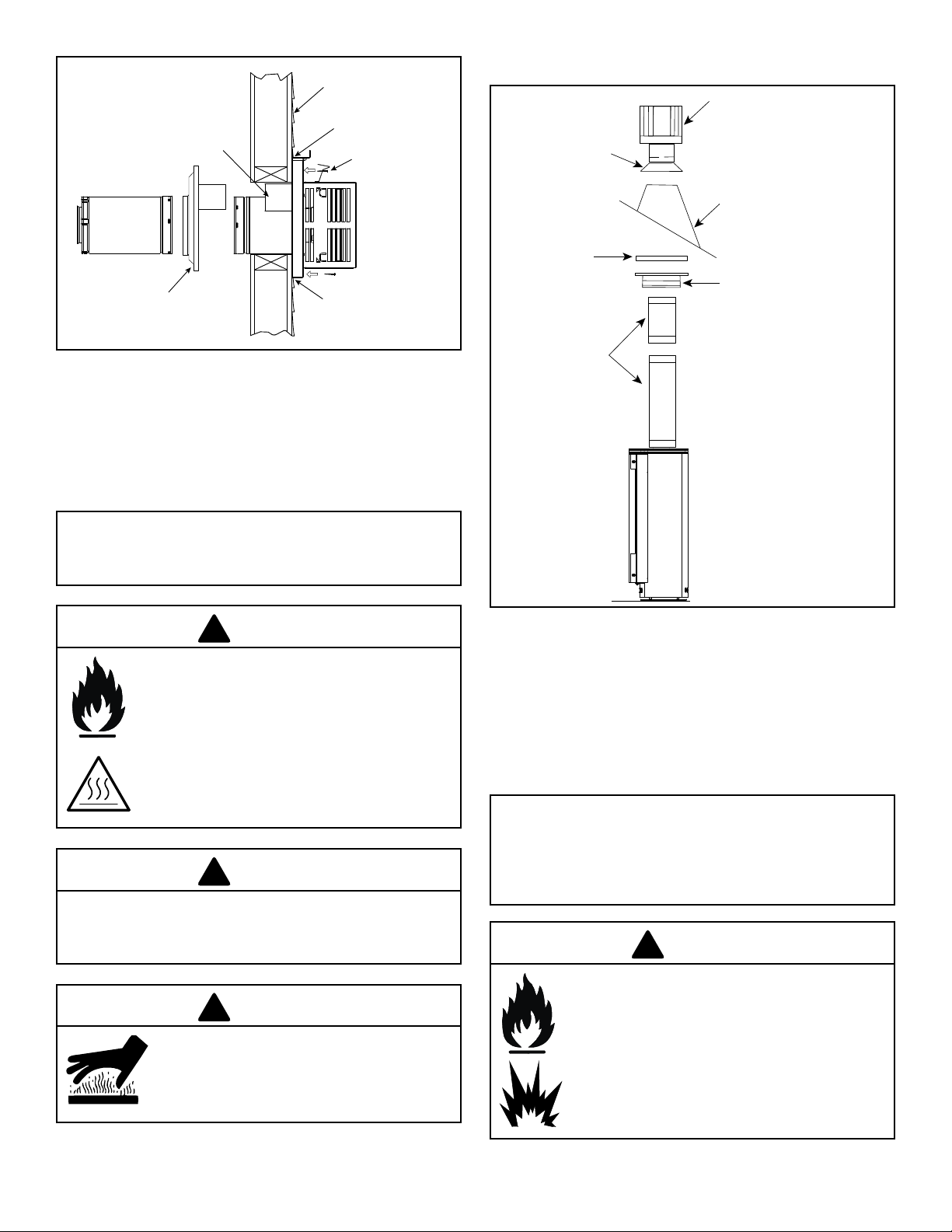
7. Position the horizontal termination cap in the center of
the 10 in. x 10 in. (254 mm x 254 mm) square hole and
run a bead of non-hardening mastic around its outside
edges, so as to make a seal between it and the wall,
attach termination cap to the exterior wall with the four
wood screws provided. The arrow on the vent cap should
be pointing up (Figure 5.6).
SLP-TRAP
Horizontal
Termination Kit
Wall Thimble
Figure 5.6
8. The four wood screws provided should be replaced with
appropriate fasteners for stucco, brick, concrete, or other
types of sidings.
9. Termination cap HHW2 (Part #841-0670) is highly
recommended on a building with vinyl siding, as the vinyl
siding standoff is built in. The pilot hole will be 2 in. (51
mm) closer to the bottom of the square than the top.
Using a framing square, draw a 14 in. x 14 in. (356 mm x
356 mm) square around the pilot hole. See Figure 5.7.
Figure 5.7
10. If you are installing termination cap HHW2, the pipe
will be off center on flashing). Ensure that proper
clearances to combustible materials are maintained. If
you are using an approved termination cap other than
HHW2 (part #841-0670) on a building with vinyl siding,
a vinyl siding standoff should be installed between
the termination cap and the exterior wall (Figure 5.8,
on the next page). Follow manufacturer’s instructions
for attaching the vinyl siding standoff to the horizontal
termination cap. The vinyl siding standoff prevents
excessive heat from possibly melting the vinyl siding
material. The vent terminal cap shall not be recessed
into a wall or siding. Remove siding from the area where
the standoff will be located.
Heat & Glo • PALOMA-BZ-MOD, PALOMA-GR-MOD, PALOMA-GY-MOD • 2189-900_R25 • 05/2014
Page 15
Wall
Thimble
Vinyl Siding Standoff with
Siding Beneath Removed
Screws
Screws
Apply sealant
to all four sides
Vinyl Siding
SLP Pipe
Heat Shield
!
!
!
G. Vertical Termination
VERTICAL TERMINATION CAP
STORM COLLAR
!
FIRESTOP
FLASHING
SUPPORT BOX
Figure 5.8
11. Place the wall thimble cover over the pipe assembly and
Note: The attachment from the vent pipe to the vent
termination cap must be sealed with silicone. Termination
caps shall not be recessed into a wall or siding.
slide the appliance and vent assembly towards the wall,
carefully inserting the vent pipe into the vent termination
cap assembly. It is important that the vent pipe extend
into the vent termination cap a sufficient distance so as
to result in a minimum pipe overlap of 1-1/4 in. (32 mm).
WARNING
Fire Risk, Exhaust Fumes Risk
Impaired Performance of Appliance
• Ensure vent components are locked
together correctly.
• Pipe may separate if not properly joined.
PIPE LENGTH
Figure 5.9
1. Check the installation instructions for required 1 in.
(25 mm) clearances (air space) to combustibles when
passing through ceilings, walls, roofs, enclosures, attic
rafters, or other nearby combustible surfaces. Check
the instructions for maximum vertical rise of the venting
system, and any maximum horizontal offset limitations.
All offsets must fall within the set parameters of the vent
graph (Figure 5.2).
WARNING
Do NOT connect a pipe section to a termination cap
without using the telescoping ue section found on the
termination cap.
WARNING
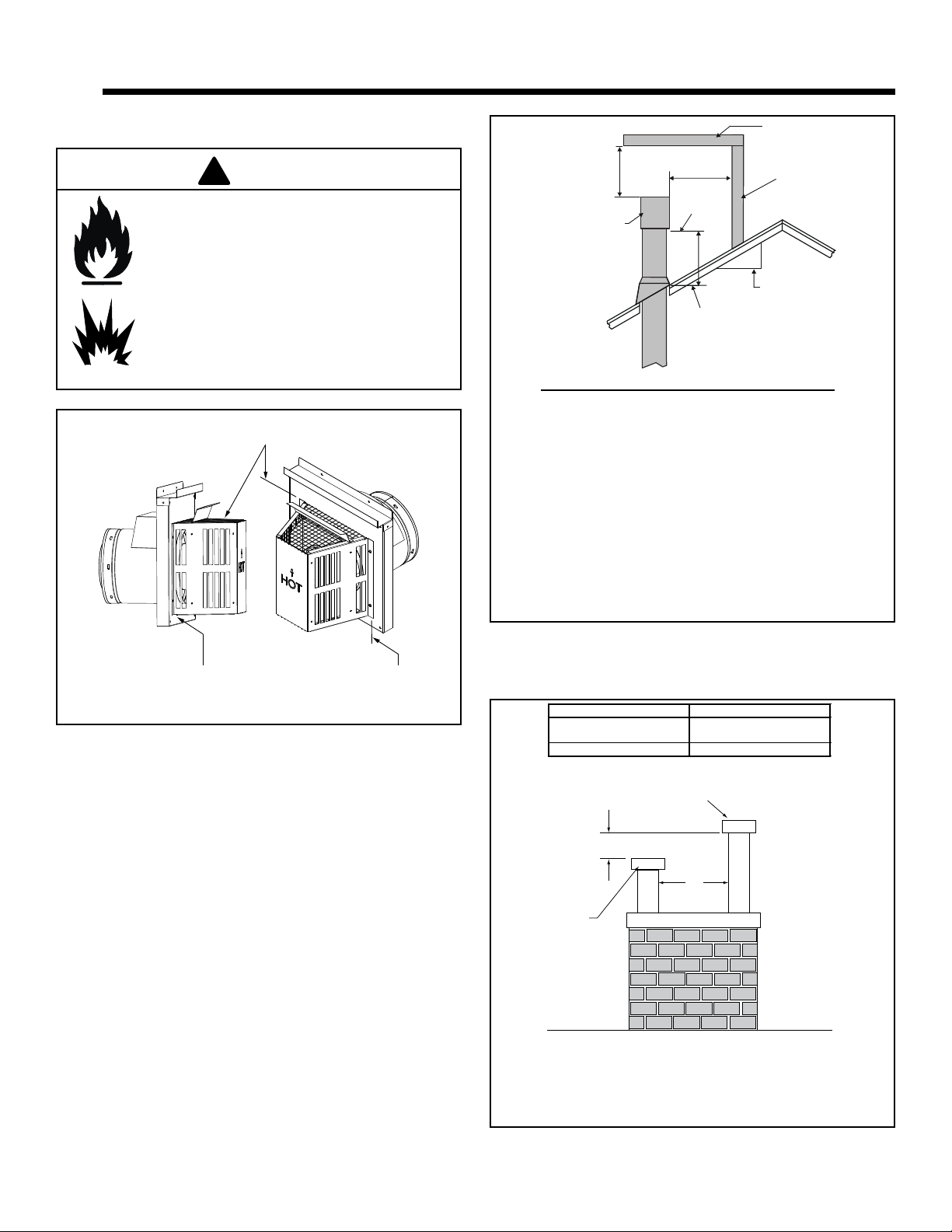
Burn Risk
• Local codes may require installation of a
cap shield to prevent anything or anyone
from touching the hot cap.
Heat & Glo • PALOMA-BZ-MOD, PALOMA-GR-MOD, PALOMA-GY-MOD • 2189-900_R25 • 05/2015
Note: Maximum vertical rise allowable is 40 ft. (10.7 m),
Figure 5.11. Maximum number of 45° elbows permitted
for a vertical installation is eight, provided their installation
does not decrease maximum allowable horizontal run (as
specied by vent graph, Figure 5.2).
WARNING
Fire Risk, Explosion Risk
Maintain vent clearance to combustibles as
specied.
• Do not pack air space with insulation or
other materials.
Failure to keep insulation or other materials
away from vent pipe may cause re.
Page 16
40 ft. (12 m)
MAXIMUM
PLUMBER'S TAPE
CONNECTED TO
WALL STRAP
WALL
STRAP
TWO 45º
ELBOWS
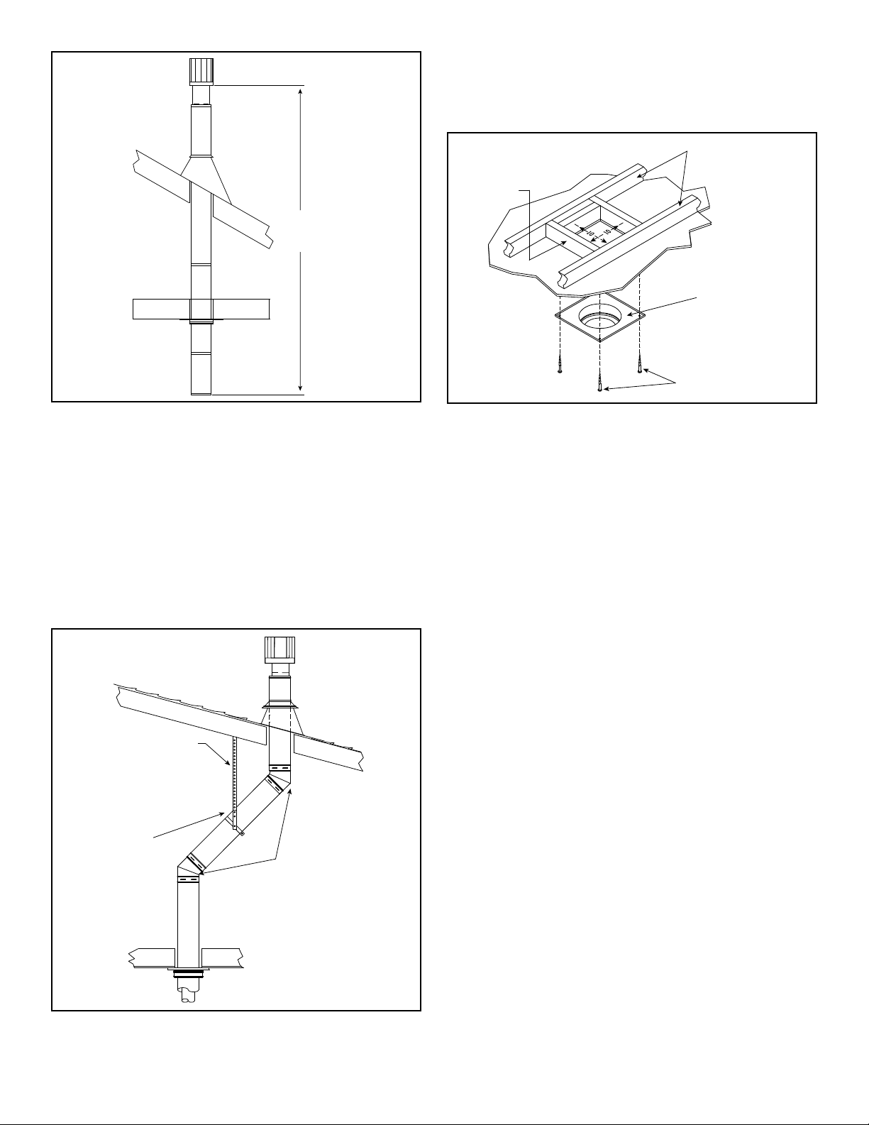
3. To install the round support box/wall thimble cover in
FRAMING
1-1/2 in. (38 mm)
LONG WOOD
SCREWS
CEILING JOISTS
ROUND CEILING
SUPPORT BOX/WALL
THIMBLE COVER
a flat ceiling, cut a 10 in. (254 mm) square hole in the
ceiling, centered on the hole drilled in Step 2. Frame the
hole as shown in Figure 5.12.
Figure 5.10
2. Set the gas appliance in its desired location. Drop a
plumb bob down from the ceiling to the position of the
appliance flue exit, and mark the location where the
vent will penetrate the ceiling. Drill a small hole at this
point. Next, drop a plumb bob from the roof to the hole
previously drilled in the ceiling, and mark the spot where
the vent will penetrate the roof. Determine if ceiling
joists, roof rafters, or other framing will obstruct the
venting system. You may wish to relocate the appliance,
or to offset, as shown in Figure 5.11 to avoid cutting load
bearing members.
Figure 5.11
Figure 5.12
4. Assemble the desired lengths of pipe and elbows
necessary to reach from the appliance up through
the round support box. Ensure that all pipe and elbow
connections are in their fully twist-locked position.
Assemble as instructed.
5. Cut a hole in the roof centered on the small drill hole
placed in the roof in Step 2. The hole should be of
sufficient size to meet the minimum requirements for
clearance to combustibles, as specified. Continue to
assemble lengths of pipe and elbows necessary to reach
from the ceiling support box/wall thimble up through the
roof line. Galvanized pipe and elbows may be utilized in
the attic, as well as above the roofline. The galvanized
finish is desirable above the roofline, due to its higher
corrosion resistance.
• If an offset is necessary in the attic to avoid obstructions,
it is important to support the vent pipe every 3 ft. (914
mm) to avoid excessive stress on the elbows, and
possible separation. Wall straps are available for this
purpose, Figure 5.11.
• Whenever possible, use 45° elbows, instead of 90°
elbows. The 45° elbow offers less restriction to the flow
of flue gases and intake air.
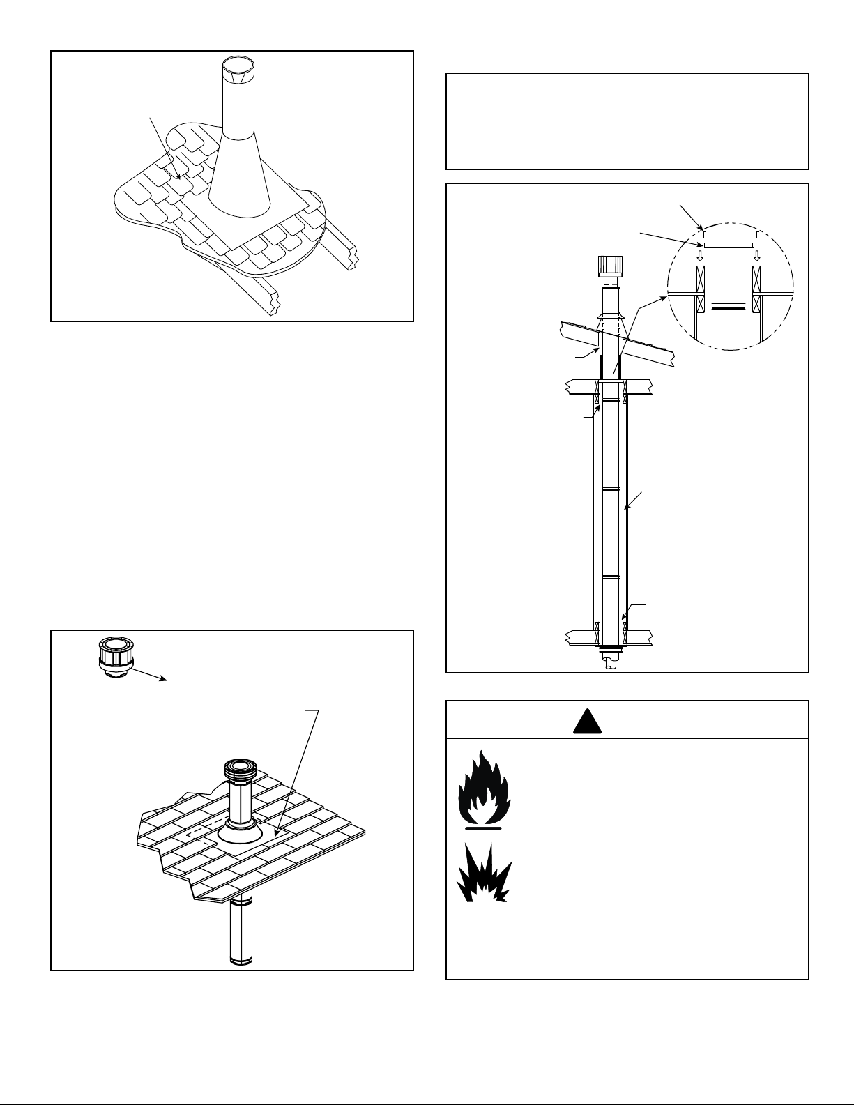
6. Slip the flashing over the pipe section(s) protruding
through the roof. Secure the base of the flashing to
the roof with roofing nails. Ensure the roofing material
overlaps the top edge of the flashing as shown in Figure
5.13. Verify that the chimney is the required height above
the roof. See roof pitch table, Figure 4.2.
Heat & Glo • PALOMA-BZ-MOD, PALOMA-GR-MOD, PALOMA-GY-MOD • 2189-900_R25 • 05/2016
Page 17
SHINGLES OVERLAP ON
TOP EDGE OF FLASHING
CAP AND STORM
COLLAR NOT SHOWN
FOR CLARITY
Figure 5.13
CEILING FIRESTOP
NAILS
MINIMUM 1 in. (25 mm)
CLEARANCE
MINIMUM 1 in.(25 mm)
CLEARANCE
MINIMUM 1 in.(25 mm)
CLEARANCE
MINIMUM 1 in.(25 mm)
CLEARANCE
!
7. Continue to assemble pipe sections until the height of
the vent (before adding the termination cap) meets the
minimum code requirements as outlined in the current
CAN/CGA-B149 Installation Codes (in Canada), the
National Fuel Gas Code NFPA 54/ANSI Z223.1 (in USA),
or local codes. Note that for steep roof pitches, the vent
height must be increased. See Roof Pitch Table (Figure
4.2). In high wind conditions, nearby trees adjoining
rooflines, steep pitched roofs, and other similar factors
can result in poor draft, or down drafting. In these cases
increasing the vent height or switching to the high wind
termination cap may solve this problem.
8. Slip the storm collar over the pipe, and push it down to
the top of the flashing (Figure 5.14). Use non-hardening
sealant above and below the joint between the storm
collar and the pipe.
9. Twist-lock the vent cap and seal.
Note: For multi-story vertical installations, a ceiling firestop
is required at the second floor, and any subsequent floors
(Figure 5.16). The opening should be framed to 10 in. x
10 in. (254 mm x 254 mm) inside dimensions, in the same
manner as shown in Figure 5.12.
Figure 5.14
OPTIONAL HIGH WIND
TERMINATION CAP
SECURE FLASHING WITH
NON-HARDENING SEALANT AND
Heat & Glo • PALOMA-BZ-MOD, PALOMA-GR-MOD, PALOMA-GY-MOD • 2189-900_R25 • 05/2017
ROOFING NAILS
Figure 5.15
WARNING
Fire Risk, Explosion Risk
• Any occupied areas above the first floor,
including closets and storage spaces,
which the vertical vent passed through
must be enclosed. The enclosure may be
framed and sheet rocked with standard
construction materials; however, refer
to these installation instructions for the
minimum allowable clearance between
the outside of the vent pipe and the
combustible surfaces of the enclosure. Do
not fill any of the required air space with
insulation.
Page 18
H. Secure the Vent Sections
!
• Vertical runs of SLP pipe must be supported every 8 ft.
(2.44 m).
• Horizontal sections must be supported every 5 feet (1.52
m).
• Vent supports or plumbers strap (spaced 120º apart) may
be used to support vent sections. See Figures 5.16 and
5.17.
• Wall shield restops may be used to provide horizontal
support to vent sections.
• SLP ceiling restops have tabs that may be used to provide
vertical support.
WARNING
RISK OF FIRE, EXPLOSION OR ASPHYXIATION!
Improper support may allow vent to sag and separate.
Use vent run supports and connect vent sections per
installation instructions. DO NOT allow vent to sag below
connection point to appliance.
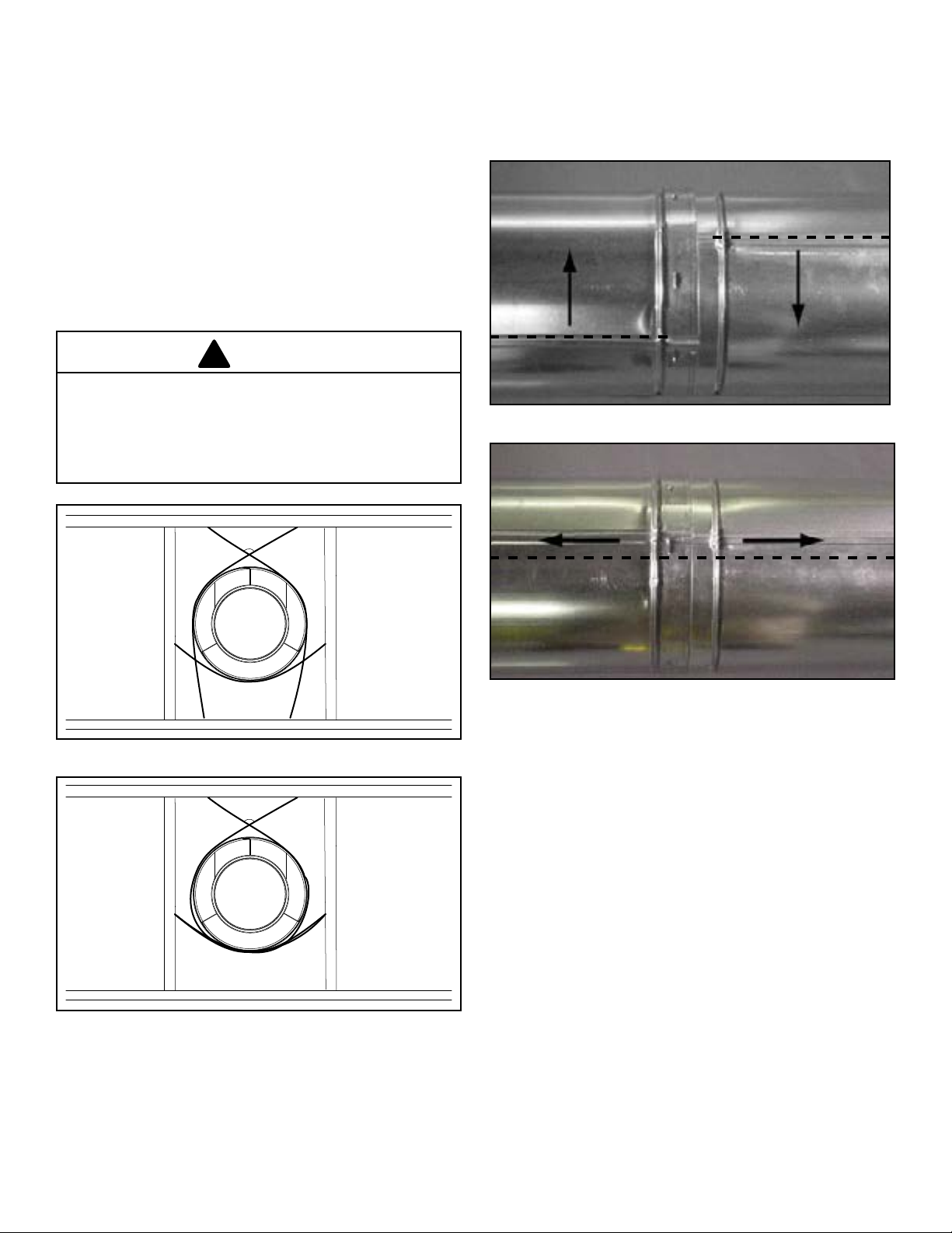
I. Disassemble Vent Sections
• Rotate either section (see Figure 5.18) so the seams on
both pipe sections are aligned as shown in Figure 5.19.
• Pull carefully to separate the pieces of pipe.
Figure 5.18 - Rotate Seams for Disassembly
120º
Figure 5.16 - Securing Vertical Pipe Sections
120º
Figure 5.19 - Align and Disassemble Vent Sections
Figure 5.17 - Securing Horizontal Pipe Sections
Heat & Glo • PALOMA-BZ-MOD, PALOMA-GR-MOD, PALOMA-GY-MOD • 2189-900_R25 • 05/2018
Page 19

J. Cathedral Ceiling
LEVEL
CATHEDRAL CEILING
SUPPORT BOX
2 in. (51 mm) MIN. BELOW
FINISHED CEILING
CUT HOLE 1/8 in. (3 mm)
GREATER IN SIZE THAN
PATTERN OF SUPPORT
BOX AS IT IS PROJECTED
ONTO ROOF LINE
!
1. Follow installation Steps 1 and 2 under vertical installation
section, page 16.
2. Remove shingles or other roof covering as necessary to
cut the rectangular hole for the support box. Cut the hole
1/8 in. (3 mm) larger than the support box outline.
3. Lower the support box through the hole in the roof
until the bottom of the support box protrudes at least
2 in. (51 mm) below the ceiling (Figure 5.20). Align the
support box both vertically and horizontally with a level.
Temporarily tack the support box in place through the
inside walls and into the roof sheathing.
Figure 5.20
4. Using tin snips, cut the support box from the top corners
down to the roofline, and fold the resulting flaps over
the roof sheathing (Figure 5.21). Before nailing it to the
roof, run a bead of non-hardening mastic around the top
edges of the support box to make a seal between it and
the roof.
Figure 5.21
6. Place the support clamp (provided with the support box)
inside the support box (at the bottom), and secure to
the pipe section. The clamp allows the support box to
support the weight of the pipe sections. Continue to add
pipe sections until you are above the roofline.
7. Complete the cathedral ceiling installation by following
the same procedures outlined in steps 7 through 9 for
vertical installations, pages 17-18.
8. Install the black trim collar around the outside of the
cathedral ceiling support box (Figure 5.22). The two
pieces of the trim collar slide over one another to allow
for easy adjustment around the support box. Using the
six screws provided, secure the four corners and the
overlapping sections of the trim collar to the ceiling. You
may want to predrill the holes for the overlapped sections
for ease of installation.
TRIM COLLAR
WARNING
RISK OF FIRE! Clean out ALL materials from inside
the support box and complete the vertical vent run
and termination.
5. Assemble the desired lengths of pipe and elbows
necessary to reach from the appliance up through
the round support box. Ensure that all pipe and elbow
connections are in their fully twist-locked position.
Assemble as instructed.
Heat & Glo • PALOMA-BZ-MOD, PALOMA-GR-MOD, PALOMA-GY-MOD • 2189-900_R25 • 05/2019
CATHEDRAL CEILING
SUPPORT BOX
SCREWS
Figure 5.22
Page 20

K. Class A Metal Chimney
Top Adapter
(Included in Link-Stove Kit)
Sheet Metal Screws
4” Flex Pipe
(Included in Link-Stove Kit)
!
TERMINATION
CAP PART #SLK-991DA
EXISTING METAL
CHIMNEY SYSTEM
DIRECT VENT
PIPE
TOP ADAPTER
FLASHING
4 in. (102 mm)
FLEX PIPE
RETRO CONNECTOR
4. Pass the flex pipe down through the center of the
chimney system, and center the top adapter on the top
of the chimney pipe. Drill four 1/8 in. (3 mm) diameter
holes through the top adapter, and into the chimney
top. Ensure that you are drilling into the metal on the
chimney. Twist lock the high wind termination cap onto
the top adapter (Figures 5.25 and 5.26).
Figure 5.23
CAUTION
Ensure that existing chimney is functionally sound and
clean.
• Have inspection done by qualied chimney sweep or
professional installer BEFORE converting to direct
vent appliance.
1. Remove existing chimney cap.
2. Measure the distance from the top of the chimney to the
bottom of the ceiling support box, add 3 in. (76 mm) to
this measurement, and cut a section of 4 in. (101 mm)
flex pipe to that length (the flex should be fully extended).
3. Connect the end of the flex pipe section to the underside
of the top adapter, using four sheet metal screws (Figure
5.24).
Figure 5.25
High Wind Termination Cap
(Part SLP-TVHW)
Sheet Metal Screws
Drill Four 1/8 in.
(3mm) Diamater
Holes
Figure 5.26
5. Pull the flex pipe down through the ceiling support box,
until it protrudes approximately 3 in. (76 mm). Connect
the flex pipe to the retro connector, and attach with sheet
metal screws.
6. Push the flex pipe back up into the ceiling support box,
center the retro connector, and attach it to the support
box with sheet metal screws.
7. The connection between the appliance and the retro
connector may be completed with sections of direct vent
pipe.
Figure 5.24
Heat & Glo • PALOMA-BZ-MOD, PALOMA-GR-MOD, PALOMA-GY-MOD • 2189-900_R25 • 05/2020
Page 21

L. Existing Masonry Chimney
!
10 in. x 10 in. (254mm x 254mm)
framed opening in wall
Studwall
Masonry
Chimney
Retro Connector
(Included in Masonry Chimney
Conversion Kit)
(4) Masonry Bolts
(Not Included)
Wall Thimble Cover
(Included in Masonry
Chimney Conversion Kit)
Cut and bend flashing as needed
to fit
Sealant adhesive
CHIMNEY LINER
TERMINATION CAP PART
#923GK
Type A
3 IN. (76 MM) FLEX LINER
CO-AXIAL TO CO-LINEAR
CONNECTOR PART
#923GCL
PIPE LENGTH
(OPTIONAL)
SHOWING TWO 30 FT.
(9 M) SECTIONS OF
FLEX LINER
Type C - Up & Out Installation
*NOTE: In the Commonwealth of Massachusetts, the word
dampershallbereplacedwiththewordsuerestrictor.
NOTE: For hearth applications refer to page 20, Figure 5.24 for the use
of the 923GCL co-axial to co-linear appliance connector.
Figure 5.28
3. Secure the flashing to the top of the masonry chimney
using a bead of non-hardening sealant-adhesive. If the
flashing is larger than the top of the chimney, cut and fold
flashing as needed to fit chimney (Figure 5.29).
Figure 5.27
Ensure that existing chimney is functionally sound and
clean.
• Have inspection done by qualied chimney sweep or
professional installer BEFORE converting to direct
vent appliance.
1. Before cutting any holes, assemble the desired sections
of direct vent pipe to determine the center of the masonry
penetration.
2. Once the center point of the penetration has been
determined, cut a 6 in. (152 mm) diameter hole in the
masonry. If the hole is too large, the retro connector
might not mount properly; if the hole is too small, the
appliance might starve for intake air. If there is a frame
wall in front of the masonry wall, cut and frame a 10
in. (254 mm) square opening in the wall (centered
around the 6 in. (152 mm) masonry opening). If there
is sheet rock only (no studs) in front of the masonry
the 10 in. (254 mm) opening is still needed, but does
not need to be framed. If the hole is framed a round
support box/wall thimble is required. This allows the
retro connector to mount directly on the masonry and
provide the correct clearances to combustibles (Figure
5.28).
CAUTION
Figure 5.29
4. To determine the length of flex needed, measure from
3 in. (76 mm) above the top of the flashing down to the
level of the opening. Add the distance from the center
of the chimney out through the wall. Cut a piece of 4
in. (102 mm) flex to this length (extended to its nominal
length). Be sure to leave 2-3 in. (51-76 mm) of flex
above the existing chimney to allow for connection to the
termination kit.
5. Connect the flex liner to the top adapter using four sheet
metal screws (Figure 5.30).
6. Feed the flex liner through the flashing into the chimney.
Carefully feed the flex liner down the chimney to the
bottom and out the opening in the masonry wall, forming
an angle to line up the flex liner with the vent opening on
the appliance.
Heat & Glo • PALOMA-BZ-MOD, PALOMA-GR-MOD, PALOMA-GY-MOD • 2189-900_R25 • 05/2021
Page 22

Flex Liner
(3 in. Part 3DFA-35)
(4 in. Part 4DFA-35)
Flex Coupler
(3 in. Part 3DFA-FC)
(4 in. Part 4DFA-FC)
Sheet Metal Screws
WARNING
!
High Wind Termination Cap
(Part SLP-TVHW)
Top Adaptor
(Included in Link-Stove Kit)
(3) Sheet Metal
Screws
Flashing
(Included in Link-Stove Kit)
6 in. (152mm) diameter
opening in masonry wall
(3) Masonry Bolts
(Not included)
Retro Connector
(Included in Masonry Chimney
Conversion Kit)
Fire Risk, Explosion Risk
• Do not let the ex liner sag below the level
at which it will connect to the appliance
or connector. This could allow hot gas to
become trapped and potentially become
a re hazard. The ex liner path should
always be sloped up toward the termination
cap.
7. If additional lengths of flex liner are needed to span the
chimney height, use a flex coupler to connect the pieces
of flex liner together. Connect the flex to the coupler
by using four sheet metal screws for each side (Figure
5.30).
Figure 5.31
Figure 5.30
8. Secure the top adapter to the flashing. Use three sheet
metal screws through the side of the top adapter into the
flange on the flashing (Figure 5.28). Twist lock the high
wind termination cap on to the top adapter.
9. Attach the flex to the retro connector. Use three sheet
metal screws to attach the flex liner to the connector
(Figure 5.32). Mount the retro connector to the masonry
wall using masonry bolts. Redrill larger holes on
connector as needed. Be careful to ensure that the
connector is centered in the opening and the mounting
holes line up with the masonry wall.
Figure 5.32
Heat & Glo • PALOMA-BZ-MOD, PALOMA-GR-MOD, PALOMA-GY-MOD • 2189-900_R25 • 05/2022
Page 23

10. Slide wall thimble cover over retro connector and
(4) Masonry Bolts
(Not included)
Retro Connector
(Included in Masonry
Chimney Conversion Kit)
Wall Thimble Cover
(Included in Masonry Chimney Conversion Kit)
secure with masonry bolts (Figure 5.33). If you have a
framed wall in front of the masonry, use wood screws
to mount wall thimble cover to framed wall, over retro
connector and 10 in. (254 mm) square framed opening
(Figure 5.28). If needed, add a section of direct vent
pipe to the retro connector in order to extend through
the opening in the wall thimble cover.
Figure 5.33
11. The connection between the appliance and the retro
connector may be completed with sections of direct
vent pipe.
Heat & Glo • PALOMA-BZ-MOD, PALOMA-GR-MOD, PALOMA-GY-MOD • 2189-900_R25 • 05/2023
Page 24

Centerline
Minimum of 6 in. (152 MM)
of Pipe Through the Wall
Interior Wall - 2 in. (51 MM)
Clearance From Rear of Stove
SLP-TRAP
Horizontal
Termination Kit
Heat Shield
SLP-WT-BK
Wall Thimble
Figure A - 90° Elbow Figure B - 45° Elbow
SLP-TRAP
Horizontal Termination Cap
Heat Shield
Centerline
SLP90
90° Elbow
SLP Pipe Length
Heat Shield
SLP-WT-BK
Wall Thimble
SLP-WT-BK
Wall Thimble
SLP Pipe Length
Figure C - Minimum Clearance
SLP-TRAP
Horizontal
Termination Kit
SLP45
45° Elbow
5 IN. (127 MM) Clearance
from Appliance Corner
to Combustible Wall
5 IN. (127 MM) Clearance
from Appliance Corner
to Combustible Wall
Figure 5.34
Heat & Glo • PALOMA-BZ-MOD, PALOMA-GR-MOD, PALOMA-GY-MOD • 2189-900_R25 • 05/2024
Page 25

6 6
!
!
Gas Information
A. Fuel Conversion
• Make sure the appliance is compatible with available gas
types.
• Conversions must be made by a qualied service technician
using Hearth & Home Technologies specied and approved
parts.
B. Gas Pressures
Proper input pressures are required for optimum appliance
performance. Gas line sizing requirements need to be made
following NFPA54.
WARNING
Fire Risk, Explosion Hazard
High pressure will damage valve.
• Disconnect gas supply piping BEFORE
pressure testing gas line at test pressures
above 1/2 psig.
• Close the manual shuto valve BEFORE
pressure testing gas line at test pressures
equal to or less than 1/2 psig.
Pressure requirements for appliance are shown in the
table below. Minimum pressures must be met when other
household gas appliances are operating.
Pressure Natural Gas Propane
Minimum inlet pressure
Maximum inlet gas
pressure
Manifold pressure
If the pressure is not sucient, ensure:
• The piping used is large enough.
• The supply regulator is adequately adjusted.
• That the total gas load for the residence does not exceed
the amount supplied.
The supply regulator (the regulator that attaches directly to
the residence inlet or to the propane tank) should supply gas
at the suggested input pressure listed above. Contact the
local gas supplier if the regulator is at an improper pressure.
5.0 inches
w.c.
7.0 inches
w.c.
3.5 inches
w.c.
11.0 inches
w.c.
14.0 inches
w.c.
10.0 inches
w.c.
WARNING
Verify inlet pressures.
• High pressure may cause overre condition.
• Low pressure may cause explosion.
• Verify minimum pressures when other
household gas appliances are operating.
Install regulator upstream of valve if line
pressure is greater than 1/2 psig.
Heat & Glo • PALOMA-BZ-MOD, PALOMA-GR-MOD, PALOMA-GY-MOD • 2189-900_R25 • 05/2025
Page 26

C. Gas Connection
!
!
!
!
Note: Have the gas supply line installed in accordance
with local building codes, if any. If not, follow ANSI
223.1. Installation should be done by a qualied installer
approved and/or licensed as required by the locality. (In
the Commonwealth of Massachusetts installation must be
performed by a licensed plumber or gas tter).
• A small amount of air will be in the gas supply lines. When
rst lighting appliance it will take a short time for air to
purge from lines. When purging is complete the appliance
will light and operate normally.
Air only needs to be purged again if gas valve has been
turned to the OFF position.
WARNING
Note: A listed (and Commonwealth of Massachusetts
approved) 1/2 inch (13 mm) T-handle manual shut-o
valve and exible gas connector are connected to the 1/2
inch (13 mm) control valve inlet.
• If substituting for these components, please consult
local codes for compliance.
WARNING
Gas Leak Risk
• Support control when attaching pipe to
prevent bending gas line.
Note: The gap between supply piping and gas access
hole may be caulked with caulk with a minimum of
300ºF continuous exposure rating or stued with non-
combustible, unfaced insulation to prevent cold air
inltration.
Leak test all gas line joints and the gas control valve prior to
and after starting the appliance.
Before making the gas connection, ensure that the appliance
you are installing is designed for the type of gas being
supplied. This information can be found on the ratings label
under the appliance. If the appliance has been converted to
propane (LP), the valve cover should have a label stating
that the appliance has been converted to propane.
Connect the gas line at the 3/8 in. (10 mm) pipe connector
on the valve at the back of appliance. We recommend
connecting the appliance with an approved flex gas line.
If flex gas lines are not approved in your area, you must
connect a hard pipe to the gas hookup.
You must supply a manual shut-off valve in a visible location
within 3 ft. (914 mm) of the appliance.
WARNING
Fire or Explosion Hazard
• Gas buildup during line purge may ignite.
• Purge should be performed by qualified
technician.
• Ensure adequate ventilation.
• Ensure there are no ignition sources such as
sparks or open ames.
CHECK FOR GAS LEAKS
Explosion Risk, Fire Risk, Asphyxiation
Risk
• Check all ttings and connections.
• Do not use open ame.
• After the gas line installation is complete,
all connections must be tightened and
checked for leaks with a commerciallyavailable, non-corrosive leak check
solution. Be sure to rinse o all leak check
solution following testing.
Fittings and connections may have loosened
during shipping and handling.
WARNING
Fire hazard
Do NOT change the valve settings.
• This valve has been preset at the factory.
• Changing valve settings may result in re
hazard or bodily injury.
HIGH ALTITUDE INSTALLATIONS
Omni-Test Laboratories, Inc. listed gas appliances are
tested and approved without requiring changes for
elevations from 0 to 2000 feet in the U.S.A. and 0 to 4500
feet in Canada.
When installing this appliance at an elevation above 2000
feet, it may be necessary to decrease the input rating
by changing the existing burner orice to a smaller size.
Input rate should be reduced by 4% for each 1000 feet
above a 2000 foot elevation in the U.S.A. If the heating
value of the gas has been reduced, these rules do not
apply. To identify the proper orice size, check with the
local gas utility.
If installing this appliance at an elevation above 4500
feet (in Canada), check with local authorities.
Heat & Glo • PALOMA-BZ-MOD, PALOMA-GR-MOD, PALOMA-GY-MOD • 2189-900_R25 • 05/2026
Page 27

7 7
!
!
Electrical Information
A. Recommendation for Wire
See Figure 7.1 for recommended maximum lead length (two
wire) when using wall thermostat/switch.
NOTE: This appliance must be electrically wired and
grounded in accordance with local codes or, in the
absence of local codes, with National Electric Code
ANSI/NFPA 70-latest edition or the Canadian Electric
Code, CSA C221.1.
• A 110-120 VAC circuit for this product must be protected
with ground-fault circuit-interrupter protection, in
compliance with the applicable electrical codes, when it is
installed in locations such as in bathrooms or near sinks.
B. Connecting to the Appliance
WARNING
Wire 110-120 VAC to electrical junction box.
Do NOT wire 110-120 VAC to valve.
Do NOT wire 110-120 VAC to wall switch.
• Incorrect wiring will damage millivolt valves.
• Incorrect wiring will override IPI safety lockout
and may cause explosion.
1. This appliance may be used with a wall switch, wall
mounted thermostat and / or a remote control
2. If using thermostat, use one compatible with a millivolt
gas valve system.
3. Follow parameters for locating thermostat (see individual
thermostat instructions) to ensure proper operation of
appliance.
4. Use low resistance thermostat wire for wiring from
ignition system to the wall switch and thermostat.
5. Use the following chart for wire sizing.
Wire Size Max. Length
16 gauge 65 feet
18 gauge 40 feet
20 gauge 25 feet
22 gauge 18 feet
Figure 7.1
6. Keep wire lengths as short as possible by removing any
excess wire length.
7. Low voltage and 110-120 VAC voltage cannot be shared
within the same wall box.
8. Ensure the thermostat is mounted level for accurate
readings.
9. The thermostat should be mounted on an inside wall and
not in direct line with the appliance convection air.
10. If the thermostat is located too close to the appliance,
you may need to set the temperature setting slightly
higher to maintain the desired temperature in your
home.
Do not connect this appliance to a thermostat serving
any other appliance.
Bedroom installation in Canada requires this appliance
to be connected to a thermostat.
WARNING
Shock hazard
• This appliance is equipped with a three This appliance is equipped with a three
pronged (grounding) plug for your pronged (grounding) plug for your
protection against shock hazard and protection against shock hazard and
should be plugged directly into a propshould be plugged directly into a properly
grounded three prong receptacle. Do not
cut or remove the grounding prong from
this plug.
C. IntelliFire® Ignition System Wiring
This appliance requires a 110-120 VAC supply to the
appliance junction box for operation. A wiring diagram is
shown in Figure 7.2 on the next page.
This appliance is equipped with an IntelliFire® control valve
which operates on a 3 volt system.
This appliance is supplied with a 3 volt AC transformer,
which requires the installation of the supplied junction box.
This appliance is supplied with a battery pack that requires
two D cell batteries (not included). Batteries cannot be placed
in the battery pack while using the 3 volt AC transformer.
Conversely, the transformer must be unplugged if the
battery pack is used.
NOTICE: Battery polarity must be correct or module damage
will occur.
Heat & Glo • PALOMA-BZ-MOD, PALOMA-GR-MOD, PALOMA-GY-MOD • 2189-900_R25 • 05/2027
Page 28

unless properly grounded.
SWITCH
Battery Location
Unplug when
!
!
!
NEUTRAL
PLUG-IN 3V
TRANSFORMER
ON/OFF
WALL
IGNITION
MODULE
VALV E
GROUND
(3V)
REMOTE
CONTROL
SPARKER/SENSOR
HOT
FLAME
BATTERY
PACK
IGNITION MODULE
3 VAC
BLACK
RED
I
S
WHT
ORG
GROUND TO
APPLIANCE CHASSIS
*
INTERMITTENT
PILOT IGNITOR
PLUG IN
JUNCTION BOX
Figure 7.2
CAUTION
Label all wires prior to disconnection when servicing
controls. Wiring errors can cause improper and dangerous
operation. Verify proper operation after servicing.
D. Loss of Power and Battery Backup Usage
1. Disconnect the power supply.
2. Remove the front door assembly and lower access
panel.
3. Place two "D" cell batteries into the battery holder.
(Figure 7.3)
4. Turn on appliance and verify it is operational.
5. Replace lower access panel and front door assembly.
TRANSFORMER
3 VAC
BRN
ON/OFF SWITCH
BRN
PIGGYBACK
ORG
VALV E
GRN
NOTE: Appliance will not operate
WARNING
Shock hazard
• Replace damaged wire with type 105º C
rated wire.
• Wire must have high temperature insulation.
using batteries
CAUTION
If IPI battery back-up is installed:
• Do not install batteries if the backup mode may not be
used for extended time.
• Batteries may leak.
• Install batteries only when needed for power outage.
Figure 7.3
Heat & Glo • PALOMA-BZ-MOD, PALOMA-GR-MOD, PALOMA-GY-MOD • 2189-900_R25 • 05/2028
Page 29

E. Wall Switch Installation for Fan (Optional)
If the box is being wired to a wall mounted switch for use
with a fan (See Figure 7.4):
• The power supply for the appliance must be brought into
a switch box.
• The power can then be supplied from the switch box to the
appliance using a minimum of 14-3 with ground wire.
• At the switch box connect the black (hot) wire and red
(switch leg) wire to the wall switch as shown.
• At the appliance connect the black (hot), white (neutral)
and green (ground) wires to the junction box as shown.
• Add a 1/4 inch insulated female connector to the red (switch
leg) wire, route it through the knockout in the face of the
junction box, and connect to the top fan switch connector
(1/4 inch male) as shown.
MINIMUM 14-3 AWG
WITH GROUND
SWITCH
JUNCTION BOX
Red
Figure 7.4 - Junction Box Wired to Wall Switch
Red
White
Black
Red
Black
Green
White
Green
Black
White
Green
POWER
SUPPLY WIRES
SWITCH BOX
Heat & Glo • PALOMA-BZ-MOD, PALOMA-GR-MOD, PALOMA-GY-MOD • 2189-900_R25 • 05/2029
Page 30

8 8
!
Appliance Setup
A. Remove Shipping Materials
Remove shipping materials from inside or underneath the
rebox.
Gas line and power cord are shipped inside back panel. To
access the gas line and power cord, remove the top plate
from the appliance. Remove and retain the two Allen head
screws that hold the back panel in place. Refer to Figure
8.8.
Using the black grommet located in the component bag,
slide it into the bottom of the back panel and feed the power
cord through the grommet, as shown in Figure 8.1.
C. Leveling and Lagging Down the Appliance
Lagging the appliance down is REQUIRED.
WARNING
Fire Risk, Odor Risk, Tipping Risk
• Install gas stove on a stable, level platform/
oor strong enough to support gas stove
without tipping.
• USE wood ooring, ceramic tile, brick hearth
or high pressure laminate ooring applied
directly over the sub-ooring material.
Securing Holes
Level
Screws
Level
Screws
Figure 8.1
B. Unbolting Appliance from the Pallet
The appliance is bolted and screwed to the pallet for
shipping. Use a 1/2 in. socket to remove the bolt in center of
bottom plate. Use a Phillips screwdriver to remove the two
screws in the front of the bottom plate and the two screws
holding the metal strap across the back of the appliance.
Refer to Figure 8.2 for locations.
Lag Bolt Hole
Securing Holes
Figure 8.3
Place the lag bolt from the component bag in the center hole
in the bottom plate (lagging clearance hole). The appliance
must be lagged down securely to prevent tipping forward,
Figure 8.4.
Lagging
Clearance
Hole
Figure 8.2
Figure 8.4
Heat & Glo • PALOMA-BZ-MOD, PALOMA-GR-MOD, PALOMA-GY-MOD • 2189-900_R25 • 05/2030
Page 31

!
The (2) leveling screws are located just inside the access
door, Figure 8.5. Using your ngers, adjust the 1/4-20 bolt to
level the appliance. Once appliance is in the level position
tighten down the 1/4-20 nut to secure the bolt, Figure 8.5.
1/4-20 Bolt
1/4-20 Nut
Figure 8.5
D. Accessories
Install approved accessories per instructions included
with accessories. See Service Parts List for appropriate
accessories. Refer to Section 12.
WARNING
Shockorrerisk.
Use ONLY optional accessories approved for
this appliance.
• Using non-listed accessories voids warranty.
• Using non-listed accessories may result in a
safety hazard.
• Only Hearth & Home Technologies approved
accessories may be used safely.
E. Top to Rear Vent Conversion
Kit Contents: Top cover (no hole); Back panel (with hole).
Tools Required: Power drill; #2 Phillips bit; 5/32 in. (4 mm)
Allen wrench; 5/8 in. (16 mm) open end wrench; high-temp
silicone sealant (optional).
1. Remove the top plate with hole and discard. (Figure 8.6).
2. Remove the front door assembly by lifting it o of the
spring-loaded latches on top of the appliance. Remove
the inner glass door by disengaging the spring-loaded
latches at the bottom of the appliance and lifting it o of
the two spring loaded latches at the top of the appliance.
Remove safety barrier from appliance by lifting over
retainer pins.
Figure 8.6
3. Remove and retain the Allen head screws that hold
the solid back panel in place. (Figure 8.7) Remove and
discard the solid back panel.
AllenHead Screws
Figure 8.7
4. Remove the four screws from the DV adapter collar.
(Figure 8.8) Set aside DV adapter collar, gasket and
screws.
5. Remove the inner extension starter collar (Shown in
Figure 8.8) and set aside.
Inner Extension Collar
DV Adapter
Figure 8.8
Heat & Glo • PALOMA-BZ-MOD, PALOMA-GR-MOD, PALOMA-GY-MOD • 2189-900_R25 • 05/2031
Page 32

6. Remove the four screws from the cover plate on rear of
appliance. Retain cover plate, gasket and screws. (see
Figure 8.9).
Figure 8.9
7. Install the outer collar with gasket to the rear of appliance
with screws previously removed. Install the inner
extension starter collar. (Figure 8.10).
8. Install the new back panel (with hole) to the rear of
appliance. Replace the allen head screws removed in
Step 3 to hold the back panel in place. (Figure 8.10).
Figure 8.11
F. Shutter Adjustment
The shutter is located on the underside of the burner, on the
burner neck (see Figure 8.12).
Figure 8.10
9. Install the cover plate and gasket removed from the
rear of the appliance to the top of the appliance with the
screws previously removed. (Figure 8.11).
10. Reinstall safety barrier by setting it over (2) placement
pins.
11. Install the new solid top.
Figure 8.12
Air Shutter Settings
PALOMA-BZ-MOD
PALOMA-BK-MOD
PALOMA-GY MOD NG LP
Rear Vent 1/2 in. 1/2 in.
Top Vent 3/8 in. 1/2 in.
Heat & Glo • PALOMA-BZ-MOD, PALOMA-GR-MOD, PALOMA-GY-MOD • 2189-900_R25 • 05/2032
Page 33

G. Installing the Vent Restrictor
!
!
The vent restrictor plate must be installed before installing
the baffle.
On the top of inside firebox for top vent ,on back of firebox
for rear vent, loosen the three screws out about 1/8 in.
Place the vent restrictor plate over the screws and slide into
locking position. Retighten the screws. (See Figure 8.13.)
Top VentTop Vent
Rear VentRear Vent
Figure 8.13
For vertical venting above 15 ft. a vent restrictor is required.
WARNING
Delayed Ignition Risk
• Place rock clusters according to instructions.
• Do NOT place rock clusters in a position that
they cover burner ports.
• Do NOT use any media other than the rock
clusters supplied with this replace.
Fireplace will not function properly.
Delayed ignition may occur.
INSTALLATION
1. Place the rear rock cluster in the rebox as shown in
Figure 8.15. The at portion should t tight against the
back of the rebox. Slide cluster to the right. There are
notches on the bottom of the rock cluster that should t
over the base pan. Cluster should rest on burner and
base pan.
H. Installing Rock Media and Ember Material
CAUTION
RISK OF CUTS OR ABRASIONS. Wear protective
gloves and safety glasses during installation.
REAR ROCK REAR ROCK
CLUSTERCLUSTER
LEFT ROCK LEFT ROCK
CLUSTERCLUSTER
RIGHT ROCK RIGHT ROCK
CLUSTERCLUSTER
NOTCHES ON NOTCHES ON
REAR ROCK REAR ROCK
CLUSTERCLUSTER
Notches Rear
Rock Cluster
Figure 8.15 - Placing Rear Rock Cluster
2. Place right rock cluster in rebox as shown in Figure 8.16.
The right end of the cluster should touch the right wall of
the rebox. Push cluster back until the rear and right rock
clusters touch as shown in Figure 8.17. Ensure the rock
clusters are not covering any burner ports.
Right Rock
Cluster
Figure 8.14 - Rock Kit Components
KIT CONTENTS
(1) Rear Rock Cluster
(1) Left Rock Cluster
(1) Right Rock Cluster
(1 ) Bag Ember Material
Figure 8.16 - Placing Right Rock Cluster
Heat & Glo • PALOMA-BZ-MOD, PALOMA-GR-MOD, PALOMA-GY-MOD • 2189-900_R25 • 05/2033
Page 34

REAR ROCK REAR ROCK
!
!
CLUSTERCLUSTER
RIGHT AND REAR CLUSTERS RIGHT AND REAR CLUSTERS
MAKE CONTACTMAKE CONTACT
RIGHT ROCK RIGHT ROCK
CLUSTERCLUSTER
LEFT ROCK LEFT ROCK
CLUSTERCLUSTER
LEFT AND REAR LEFT AND REAR
CLUSTERS CLUSTERS
MAKE CONTACTMAKE CONTACT
REAR ROCK REAR ROCK
CLUSTERCLUSTER
Figure 8.17 - Right and Rear Rock Clusters Make Contact
3. Place left rock cluster in rebox as shown in Figure 8.18.
The left end of the cluster should touch the left wall of
the rebox. Push cluster back until the rear and left rock
clusters contact each other as shown in Figure 8.19.
Ensure the rock clusters are not covering any burner ports.
WARNING
RISK OF EXPLOSION! Follow instructions for placing
rock clusters. DO NOT allow rock cluster to cover burner
ports. Improperly placed rock cluster will interfere with
proper burner operation.
LEFT ROCK
CLUSTER
Figure 8.19 - Left and Rear Rock Clusters Make Contact
4. Ember material is shipped with this kit. To place the ember
material:
WARNING
RISK OF EXPLOSION! Follow ember placement
instructions. DO NOT place embers directly over burner
ports. Replace ember material annually. Improperly placed
embers interfere with proper burner operation.
• Embers CANNOT be placed directly over ports. Care
should be taken not to cover the lighting trail of ports (from
back to front).
• Place dime-size pieces of embers in the areas highlighted
in Figure 8.20. Care should be taken so that the ports are
not covered. Failure to follow this procedure will likely cause
lighting and sooting problems.
EMBERS
Figure 8.18 - Placing Left Rock Cluster
Heat & Glo • PALOMA-BZ-MOD, PALOMA-GR-MOD, PALOMA-GY-MOD • 2189-900_R25 • 05/2034
BASEPAN LEDGE
Figure 8.20 - Ember Placement
Page 35

I. Optional Blower
BLOWER
CONTROL
KNOB
GROUND
CLIP
CONTROL
NUT
SPEED
CONTROL
WING
NUT
TEMP.
SENSOR
SWITCH
!
!
The GFK-160A Blower has been designed to circulate room
air through the appliance to enhance heat output.
The GFK-160A blower system operates on 120 VAC, 60 Hz
power. This is available through a receptacle in the factory
installed junction box. The junction box is mounted in the
bottom of the appliance behind the access panel. A variable
speed control is provided with the blower system to provide
quiet forced air flow at the desired speeds. A temperature
sensor switch, which automatically turns the blower ON/
OFF, is also provided with this kit.
Compare contents of carton with the actual parts received.
If any parts are missing or damaged, contact your dealer
before starting installation. Do not install a damaged blower
kit. See Figure 8.21.
WARNING
Shock Risk, Explosion Risk
Do NOT wire 110-120 VAC to gas control
valve.
Do NOT wire 110-120 VAC to wall switch.
• Incorrect wiring will damage millivolt valves.
• Incorrect wiring will override IPI safety lockout
and may cause explosion.
Disconnect all electrical power. Remove the front door
assembly by lifting off of appliance. Remove the lower
access door. See Figure 8.22.
Figure 8.21
Installation precautions
The GFK-160A Blower kit is tested and safe when
installed in accordance with this installation manual. It is
your responsibility to read all instructions before starting
installation and to follow these instructions carefully during
installation to assure maximum benefit from, and safe
operation, of the blower.
This blower is carefully engineered and must be installed
only as specified. If you modify it or any of its components,
you may cause a fire hazard and will void the WARRANTY.
In addition, such action may void the coverage provided by
the owner's home insurance.
CAUTION
All wiring should be done by a qualified electrician and
shall be in compliance with local codes and with the
National Electric Code ANSI/NFPA NO. 70-current (in the
United States), or with the current CSA C22.1 Canadian
Electric Code (in Canada).
Figure 8.22
Attach enclosed wires to the temperature sensor switch/
bracket assembly. The blue wire attaches to the rear of the
bracket and one of the black wires from the variable speed
control attaches closest to the prepunched screw hole. See
Figure 8.23.
Black WiresBlack Wires
Figure 8.23
Blue WiresBlue Wires
Feed the blue wire and other black wire from the variable
speed control behind the gas valve assembly. Insert the
wires into the slots indicated in Figure 8.28.
Heat & Glo • PALOMA-BZ-MOD, PALOMA-GR-MOD, PALOMA-GY-MOD • 2189-900_R25 • 05/2035
Page 36

Locate the machine screw underneath the firebox on the
right side. Position the temperature sensor switch/bracket
assembly over the machine screw and attach with the wing
nut. Finger tighten. See Figure 8.24.
Figure 8.24
Note: The switch/bracket assembly must be installed so
that the sensor switch makes contact with the bottom of
the rebox.
Attach rheostat in mating feature of control shield so that
orientation of control knob is downward. See Figure 8.25.
Attach the ground clip to the control panel. Attach the ground
wire extension to the ground clip. Attach the blower ground
wire to the ground wire extension. Refer to Figure 8.26.
Figure 8.26
Plug the blower cord into the FAN outlet on the junction box.
Push excess wires neatly towards the rear of the appliance.
Slide the blower into the bracket as indicated in Figure 8.27.
Ensure the blower is pushed back into the bracket to allow
the replacement of the lower access door. The magnet
strips located on the blower feet are designed to hold the
blower in place.
Plug appliance in. Turn the 110-120 VAC service "ON" at
the circuit breaker and turn the speed control switch to the
"ON" position.
Figure 8.25
FAN BASE CONTACTS FAN BASE CONTACTS
FAN BRACKETFAN BRACKET
Figure 8.27
Heat & Glo • PALOMA-BZ-MOD, PALOMA-GR-MOD, PALOMA-GY-MOD • 2189-900_R25 • 05/2036
Page 37

Recommended operating procedures
BLUE
VARIABLE
SPEED SWITCH
TEMPERATURE
SENSOR SWITCH
JUNCTION BOX
!
Ignite the fire in the appliance with the variable speed control
switch in an "ON" position. The fan will automatically turn on
when the temperature sensor switch closes at approximately
110 degrees Fahrenheit. Heated air should be delivered at
the outlet grille. The fan will continue to operate after the
appliance is turned OFF until the sensor switch opens.
Various conditions (such as appliance model, type of
appliance installation, outside air temperature vs. inside air
temperature) can contribute to the length of the time the
blower remains on after the appliance is turned OFF. The
blower can be turned off manually with the speed control
switch.
WARNING
RISK OF SHOCK! Replace damaged wire with type
105º C rated wire. Wire must have high temperature
insulation.
Figure 8.28 - Blower Wiring Diagram
Heat & Glo • PALOMA-BZ-MOD, PALOMA-GR-MOD, PALOMA-GY-MOD • 2189-900_R25 • 05/2037
Page 38

J. Remote Controls
WASHER
GAS CONTROL
VALVE
FLAME CONTROL
SOLENOID
VARIABLE
REGULATOR
VARIABLE
REGULATOR
PLUNGER
JAM NUT
WASHER
NUT
SCREW
KNOB
FLAME
CONTROL
SOLENOID
Tools Required: Powered screwdriver with Phillips head
bit; hex wrench; 7/16 in. wrench; manometer.
Disconnect electricity at the circuit breaker before beginning
this installation.
Familiarize yourself with the instructions enclosed with the
remote control kit.
Remote receiver
Remove the top plate from the appliance. Remove the Allen
head screws attaching the back panel to the appliance.
Retain screws.
Remove the front glass door assembly and the lower access
door.
Using two wire ties from the appliance component bag,
mount the remote receiver to the rear of the control panel.
Feed the red and orange wires to the front of the appliance.
Remove the optional blower, if installed.
Plug the 3-prong remote receiver cord into the junction box
(REM/AUX). Refer to Figure 8.29.
Plug the 2-prong blower cord directly into the 3-prong
polarized plug on the back of the receiver. This receptacle
output is 110/120 VAC, 3 AMP.
Attach the ground wire from the blower onto the grounding
clip.
Attach red wires from the remote receiver to the ON/OFF
switch.
Reinstall the blower into the blower bracket.
Installing flame control solenoid
Remove the screw and knob from the variable regulator and
discard. Unscrew the nut from the regulator and discard.
Remove the bag containing a washer and blue and red
plungers from the side of the flame control solenoid.
Place washer on flame control solenoid. Insert the correct
plunger (blue - Natural Gas, red - Propane) into the flame
control solenoid.
Thread the flame control solenoid with the correct plunger
into the thread hole in the variable regulator. Turn one to
two turns only. DO NOT tighten or damage may occur. See
Figure 8.30.
Figure 8.29
3 Prong Cord3 Prong Cord
Wires TiesWires Ties
Figure 8.30 - Flame Control Solenoid
Heat & Glo • PALOMA-BZ-MOD, PALOMA-GR-MOD, PALOMA-GY-MOD • 2189-900_R25 • 05/2038
Page 39

WHITE
ORANGE
INTERMITTENT
PILOT IGNITOR
IGNITION MODULE
3 VAC
REMOTE RECEIVER
ORANGE
GREEN
BLACK
RED
VALVE
GROUND TO
FIREPLACE CHASSIS
TRANSFORMER
3 VAC
PLUG
IN
ORANGE
ORANGE
RED
FLAME
CONTROL
SOLENOID
BATTERY PACK
I
S
RED
ORANGE
ORANGE
BRN
ORANGE
ORANGE
BRN
PIGGYBACK
ON/OFF SWITCH
REMOTE
RECEIVER
BRN
BRN
Wiring the flame control solenoid:
Connect the two leads from the flame control solenoid to the
orange leads from the receiver. See Figure 8.31.
Install a manometer into the pressure tap. Plug the remote
receiver into the 110-120 VAC power supply.
Light the appliance as directed in Section 9 of this manual.
Set the manifold pressure on the gas valve by rotating
the flame control solenoid. Adjust until the reading on the
manometer is 3.5 in. W.C. for natural gas or 10 in. W.C. for
Propane.
Tighten the jam nut to the face of the variable regulator
body. See Figure 8.30. Turn the main gas knob on the gas
valve OFF. Remove the manometer from the pressure tap
and screw the tap closed.
Follow the instructions from the remote control kit to operate
and program the remote control.
Figure 8.31 - Remote Control IPI Wiring Diagram
Heat & Glo • PALOMA-BZ-MOD, PALOMA-GR-MOD, PALOMA-GY-MOD • 2189-900_R25 • 05/2039
Page 40

K. Front Door Glass Assembly Replacement
CAP AND BARREL FASTENER SYSTEM
Nylon washer on back
and front of glass
Screw
Finishing Cap
Protective barrel sleeve
through hole in the glass
Back side of
front door
!
Lift top plate slightly on top of appliance. Remove safety
barrier by lifting it over retainer pins.
Remove the front door assembly by pulling bottom of front
away from appliance and lifting it o of the spring-loaded
latches on top of the appliance. See Figure 8.32.
Figure 8.32
Position the four at 1/4 in. (6 mm) spacer washers on the
front door so that the four mounting screws pass through
them. Position the glass over the front door.
Install the four protective barrels into the glass and the four
nylon washers on top of the glass.
From inside the door front, pass the screws through to the
outside and thread on the caps until tight. See Figure 8.33.
L. Inner Glass Door Assembly Replacement
Turn the appliance OFF and let it cool down before replacing
the inner glass door assembly.
With the safety barrier and front door assembly removed
from the appliance, remove the inner glass door assembly
by disengaging the spring-loaded latches at the bottom of
the appliance and lifting o of the two spring-loaded latches
at the top of the appliance.
Replace with a new inner glass door assembly.
Figure 8.34 - Complete Assembly
Figure 8.33
WARNING
RISK OF ASPHYXIATION! Handle glass door
assembly with care. Inspect the gasket to ensure it is
undamaged and inspect the glass for cracks, chips or
scratches.
• DO NOT strike, slam or scratch glass.
• DO NOT operate replace with glass removed, cracked,
broken or scratched.
• Replace glass door as a complete assembly.
Heat & Glo • PALOMA-BZ-MOD, PALOMA-GR-MOD, PALOMA-GY-MOD • 2189-900_R25 • 05/2040
Page 41

9 9
!
!
!
!
!
Operating Instructions
A. Before Lighting Appliance
Read this entire manual prior to using the appliance. Failure
to follow the instructions may result in property damage,
bodily injury, or even death.
CAUTION
WARNING
HOT SURFACES!
Glass and other surfaces are hot
during operation AND cool down.
Hot glass will cause burns.
If installing IntelliFire ignition battery backup:
• Do not install batteries if the backup mode may not be
used for extended time.
• Batteries may leak.
• Install batteries only when needed for power outage.
Before operating this appliance have a qualified
technician:
• Remove all shipping materials from inside and/or
underneath the rebox.
• Review proper placement of logs and mineral wool.
• Check the wiring.
• Check the bae adjustment.
• Ensure that there are no gas leaks.
• Ensure that the glass is sealed and in the proper position.
• Ensure that the ow of combustion and ventilation air is
not obstructed (front grilles and vent caps).
WARNING
Glass door must be in place when appliance
is operating.
Risk of:
• Combustion Fumes
• Fire
Do NOT operate appliance with glass door
removed.
• Open viewing glass for servicing only.
• Glass door MUST be in place and sealed before
operating appliance.
• Only use glass door certied for use with appliance.
• Glass replacement should be done by qualified
technician.
• Do not touch glass until it is cooled
• NEVER allow children to touch glass
• Keep children away
• CAREFULLY SUPERVISE children in same room as
replace.
• Alert children and adults to hazards of high temperatures.
High temperatures may ignite clothing or other
ammablematerials.
• Keep clothing, furniture, draperies and other ammable
materials away.
WARNING
RISK OF FIRE, EXPLOSION OR ELECTRIC SHOCK!
DO NOT use this appliance if any part has been under
water. Call a qualied service technician to inspect the
appliance and to replace any part of the control system
and/or gas control which has been under water.
B. Controls
On/off Switch: When this switch is in the ON position, the
pilot ignitor is engaged until temperature is established. The
burner automatically turns on.
Valve Variable Control:
from low (“LO”) to high (“HI”).
indicates the position of the knob.
Variable Speed Control: The blower is optional installed
on the appliance and this knob controls the speed of the
blower that pushes the heated air into the room.
Note: If using a remote control wall switch, or thermostat, the
On/Off Switch must be left “OFF”. Turning the On/Off Switch
to “ON” will keep the appliance on continually.
This knob controls the flame height
The indicator on the valve
CONTROL PANEL
WARNING
Improper installation, adjustment, alteration, service
or maintenance can cause injury or property damage.
Refer to the owner’s information manual provided with
this appliance. For assistance or additional information
consult a qualied installer, service agency or the gas
supplier.
Heat & Glo • PALOMA-BZ-MOD, PALOMA-GR-MOD, PALOMA-GY-MOD • 2189-900_R25 • 05/2041
Valve Variable Control
Figure 9.1
Variable Speed
Control Knob
Optional Future
Switch Location
ON/OFF Switch
Page 42

C. Lighting Instructions (IPI)
!
The IPI system may be operated with two D-cell batteries. When using batteries, unplug the transformer. To prolong battery
life, remove them when using the transformer.
FOR YOUR SAFETY READ BEFORE LIGHTING
WARNING: If you do not follow these instructions exactly, a re or explosion
may result causing property damage, personal injury or loss of life.
A. This appliance is equipped with an intermittent pilot ignition (IPI) device
which automatically lights the burner. DO NOT try to light the burner by
hand.
B. BEFORE LIGHTING, smell all around the appliance area for gas. Be sure to
smell next to the oor because some gas is heavier than air and will settle on
the oor.
WHAT TO DO IF YOU SMELL GAS
• DO NOT try to light any appliance.
• DO NOT touch any electric switch; do not use any phone in your building.
LIGHTING INSTRUCTIONS (IPI)
1. This appliance is equipped with an ignition device which automatically
lights the burner. DO NOT try to light the burner by hand.
GAS
VALVE
TO TURN OFF GAS TO APPLIANCE
1. Equipped with wall switch: Turn ON/OFF switch to OFF.
Equipped with remote or wall control: Press OFF button.
Equipped with thermostat: Set temperature to lowest setting.
• Immediately call your gas supplier from a neighbor’s phone. Follow the gas
supplier’s instructions.
• If you cannot reach your gas supplier, call the re department.
C. Use only your hand to push in or turn the gas control knob. Never use Tools. If
the knob will not push in or turn by hand, DO NOT try to repair it, call a qualied
service technician. Force or attempted repair may result in a re or explosion.
D. DO NOT use this appliance if any part has been under water. Immediately call
a qualied service technician to inspect the appliance and to replace any part
of the control system and any gas control which has been under water.
2. Wait ve (5) minutes to clear out any gas. Then smell for gas, including near the
oor. If you smell gas, STOP! Follow “B” in the Safety Information located on the
left side of this label. If you do not smell gas, go to next step.
3. To light the burner:
Equipped with wall switch: Turn ON/OFF switch to ON.
Equipped with remote or wall control: Press ON or FLAME button.
Equipped with thermostat: Set temperature to desired setting.
4. If the appliance does not light after three tries, call your service technician or gas
supplier.
2. Service technician should turn off electric power to the control when performing
service.
DANGER
A barrier designed to reduce the risk of burns from the hot viewing glass is provided with this
appliance and shall be installed for the protection of children and other at-risk individuals.
DO NOT CONNECT LINE VOLTAGE (110/120 VAC OR 220/240 VAC) TO
THE CONTROL VALVE.
Improper installation, adjustment, alteration, service or maintenance can
cause injury or property damage. Refer to the owner’s information manual
provided with this appliance.
This appliance needs fresh air for safe operation and must be installed so
there are provisions for adequate combustion and ventilation air.
If not installed, operated, and maintained in accordance with the manufacturer’s
instructions, this product could expose you to substances in fuel or fuel
combustion which are known to the State of California to cause cancer, birth
defects, or other reproductive harm.
Keep burner and control compartment clean. See installation and operating
instructions accompanying appliance.
For additional information on operating your
Hearth & Home Technologies replace, please refer to www.replaces.com.
HOT GLASS WILL CAUSE BURNS.
DO NOT TOUCH GLASS UNTIL COOLED.
NEVER ALLOW CHILDREN TO TOUCH GLASS.
CAUTION:WARNING:
Hot while in operation. DO NOT touch. Keep children, clothing, furniture, gasoline
and other liquids having ammable vapors away.
DO NOT operate the appliance with xed glass assembly removed, cracked or
broken. Replacement of the xed glass assembly should be done by a licensed
or qualied service person.
NOT FOR USE WITH SOLID FUEL
For use with natural gas and propane. A conversion kit, as supplied by the
manufacturer, shall be used to convert this appliance to the alternate fuel.
Also Certied for Installation in a Bedroom or a Bedsitting Room.
For assistance or additional information, consult a qualied installer, service
agency or the gas supplier.
593-913i
Heat & Glo • PALOMA-BZ-MOD, PALOMA-GR-MOD, PALOMA-GY-MOD • 2189-900_R25 • 05/2042
Page 43

D. After Appliance is Lit
!
!
!
!
Initial Break-in Procedure
When you light the appliance, you may notice that it produces
heat which does have an associated odor or smell. If you
feel this odor is excessive it may require the initial three
to four hour continuous burn on high followed by a second
burn up to 12 hours to fully drive o any odor from paint and
lubricants used in the manufacturing process. Condensation
of the glass is normal.
NOTE: The appliance should be run three to four hours on the
initial start-up. Turn it o and let it cool completely. Remove
and clean the glass. Replace the glass and run the appliance
for an additional 12 hours. This will help to cure the products
used in the paint and logs.
During this break-in period it is recommended that some
windows in the house be opened for air circulation. This will
help avoid setting o smoke detectors, and help eliminate any
odors associated with the appliance’s initial burning.
WARNING
Fire Risk.
High Temperatures.
Keep combustible household items away
from appliance.
Do NOT obstruct combustion and ventilation air.
• Do NOT place combustible items on top of or in front of
appliance.
• Keep furniture, draperies away from appliance.
CAUTION
• Prevent accidental appliance operation when not
attended.
• Unplug or remove batteries from remote control if absent
or if appliance will not be used for an extended period
of time.
• Property damage possible from elevated temperatures.
CAUTION
Smoke and odors released during initial operation.
• Open windows for air circulation.
• Leave room during initial operation.
• Smoke may set o smoke detectors.
Smoke and odors may be irritating to sensitive individuals.
WARNING
Fire Hazard.
Keep combustible materials, gasoline and
other ammable vapors and liquids clear of
appliance.
• Do NOT store ammable materials in the
appliance’s vicinity.
• Do NOT use gasoline, lantern fuel, kerosene, charcoal
lighter uid or similar liquids in this appliance.
• Combustible materials may ignite.
E. Frequently Asked Questions
ISSUE SOLUTIONS
Condensation on the glass
Blue ames
Odor from replace
Film on the glass
Metallic noise
Is it normal to see the pilot ame burn
continually?
This is a result of gas combustion and temperature variations. As the replace warms, this
condensation will disappear.
This is a result of normal operation and the ames will begin to yellow as the replace is allowed to burn for 20 to 40 minutes.
When rst operated, this replace may release an odor for the rst several hours. This is caused
by the curing of the paint and the burning o of any oils remaining from manufacturing. Odor may
also be released from nishing materials and adhesives used around the replace.
This is a normal result of the curing process of the paint. Glass should be cleaned within 3
to 4 hours of initial burning to remove deposits left by oils from the manufacturing process. A
non-abrasive cleaner such as gas replace glass cleaner may be necessary. See your dealer.
Noise is caused by metal expanding and contracting as it heats up and cools down, similar to
the sound produced by a furnace or heating duct. This noise does not aect the operation or
longevity of the replace.
In an intermittent pilot ignition system (IPI), the pilot ame should turn o when appliance is
turned o. Some optional control systems available with IPI models may allow pilot ame to
remain lit. In a standing pilot system the pilot will always stay on.
Heat & Glo • PALOMA-BZ-MOD, PALOMA-GR-MOD, PALOMA-GY-MOD • 2189-900_R25 • 05/2043
Page 44

10 10
Troubleshooting
With proper installation, operation, and maintenance your gas appliance will provide years of trouble-free service. If you do
experience a problem, this troubleshooting guide will assist a qualied service technician in the diagnosis of a problem and
the corrective action to be taken. This troubleshooting guide can only be used by a qualied service technician. Contact your
dealer to arrange a service call by a qualied service technician.
A. IntelliFire Ignition System
Symptom Possible Cause Corrective Action
1. Pilot won’t light.
The ignitor/module
makes noise, but no
spark.
2. Pilot won’t light,
there is no noise or
spark.
A. Incorrect wiring. Verify “S” wire (white) for sensor and “I” wire (orange) for ignitor are
connected to correct terminals on module and pilot assembly.
B. Loose connections or electrical
shorts in the wiring.
C. Ignitor gap is too large. Verify gap of igniter to right side of pilot hood. The gap should be
D. Module. Turn ON/OFF rocker switch or wall switch to OFF position. Remove
A. No power or transformer installed
incorrectly.
B. A shorted or loose connection
in wiring conguration or wiring
harness.
Verify no loose connections or electrical shorts in wiring from module
to pilot assembly. Verify connections underneath pilot assembly are
tight; also verify connections are not grounding out to metal chassis,
pilot burner, pilot enclosure, mesh screen if present, or any other
metal object.
approximately .17 in. or 1/8 in. (3 mm).
ignitor wire “I” from module. Place a grounded wire about 3/16 in. (5
mm) away from “I” terminal on module. Place ON/OFF rocker switch
or wall switch in ON position. If there is no spark at “I” terminal module
must be replaced. If there is a spark at “I” terminal, module is ne.
Inspect pilot assembly for shorted sparker wire or cracked insulator
around electrode. Replace pilot if necessary.
Verify that transformer is installed and plugged into module. Check
voltage of transformer under load at spade connection on module
with ON/OFF switch in ON position. Acceptable readings of a good
transformer are between 3.2 and 2.8 volts AC.
Remove and reinstall the wiring harness that plugs into module.
Verify there is a tight t. Verify pilot assembly wiring to module.
Remove and verify continuity of each wire in wiring harness.
Replace any damaged components.
3. Pilot sparks, but
Pilot will not light.
C. Improper wall switch wiring. Verify that 110-120 VAC power is “ON” to junction box.
D. Module not grounded. Verify black ground wire from module wire harness is grounded to
metal chassis of appliance.
E. Module. Turn ON/OFF rocker switch or wall switch to OFF position. Remove
ignitor wire “I” from module. Place ON/OFF rocker switch or wall
switch in ON position. If there is no spark at “I” terminal module
must be replaced. If there is a spark at “I” terminal, module is ne.
Inspect pilot assembly for shorted sparker wire or cracked insulator
around electrode.
A. Gas supply. Verify that incoming gas line ball valve is “open”. Verify that inlet
pressure reading is within acceptable limits, inlet pressure must not
exceed 14 in. W.C.
B. Ignitor gap is too large. Verify gap of igniter to right side of pilot hood. The gap should be
approximately .17 in. or 1/8 in. (3 mm).
C. Module is not grounded. Verify module is securely grounded to metal chassis of appliance.
D. Module voltage output / Valve/Pilot
solenoid ohms readings.
Heat & Glo • PALOMA-BZ-MOD, PALOMA-GR-MOD, PALOMA-GY-MOD • 2189-900_R25 • 05/2044
Verify battery voltage is at least 2.7 volts. Replace batteries if
voltage is below 2.7.
Page 45

IntelliFire Ignition System - (continued)
Symptom Possible Cause Corrective Action
4. Pilot lights but
continues to spark,
and main burner will
not ignite. (If the pilot
continues to spark after
the pilot ame has been
lit, ame rectication
has not occurred.)
A. A shorted or loose connection in ame
sensing rod.
B. Poor ame rectication or contaminated
ame sensing rod.
C. Module is not grounded. Verify module is securely grounded to metal chassis of
D. Damaged pilot assembly or contami-
nated ame sensing rod.
E. Module. Turn ON/OFF rocker switch or wall switch to OFF position.
Verify all connections to wiring diagram in manual. Verify
connections underneath pilot assembly are tight. Verify
connections are not grounding out to metal chassis, pilot
burner, pilot enclosure or screen if present, or any other
metal object.
With xed glass assembly in place, verify that ame is
engulng ame sensing rod on left side of pilot hood. Flame
sensing rod should glow shortly after ignition. Verify correct
pilot orice is installed and gas inlet is set to pressure
specications. Polish ame sensing rod with ne steel wool
to remove any contaminants that may have accumulated on
ame sensing rod.
appliance. Verify that wire harness is rmly connected to
the module.
Verify that ceramic insulator around the ame sensing
rod is not cracked, damaged, or loose. Verify connection
from ame sensing rod to white sensor wire. Polish ame
sensing rod with ne steel wool to remove any contaminants
that may have accumulated on ame sensing rod. Verify
continuity with a multimeter with ohms set at lowest range.
Replace pilot if any damage is detected.
Remove ignitor wire “I” from module. Place ON/OFF rocker
switch or wall switch in ON position. If there is no spark at “I”
terminal module must be replaced. If there is a spark at “I”
terminal, module is ne.
Heat & Glo • PALOMA-BZ-MOD, PALOMA-GR-MOD, PALOMA-GY-MOD • 2189-900_R25 • 05/2045
Page 46

11 11
!
!
!
!
Although the frequency of appliance servicing and maintenance will depend on use and the type of installation, a qualied
service technician should perform an appliance checkup at the beginning of each heating season.
Maintaining and Servicing Appliance
WARNING
Risk of injury or property damage.
Before servicing:
• Turn o gas.
• Turn o electricity to appliance.
• Disable remote control, if one is present.
• Ensure appliance is completely cooled.
After servicing:
• Replace any screen or barrier that was removed.
• Reseal and reinstall any venting removed for servicing.
WARNING
Annual inspection by qualied
technician recommended.
Check:
• Condition of glass, glass assembly and glass seal.
• Obstructions of combustion and ventilation air.
• Burner ignition and operation.
• Burner air shutter adjustment
• Gas connections and ttings.
• Obstructions of termination cap.
Clean:
• Glass
• Air passageways, grilles, control compartment
• Burner, burner ports
Risk of:
• Fire
• Delayed ignition or explosion
• Exposure to combustion fumes
• Odors
CAUTION
Handle glass assembly with care.
NOTE: Clean glass after initial 3-4 hours
operation. Longer operation without
cleaning glass may cause a permanent
whitelmonglass.
When cleaning glass door:
• Avoid striking, scratching or slamming glass.
• Do NOT use abrasive cleaners.
• Use a hard water deposit glass cleaner on white lm.
• Do NOT clean glass when hot.
• Turn o appliance after 3-4 hours of operation and
ALLOW TO COOL.
• Remove and clean glass assembly.
• Replace glass assembly and operate appliance for
additional 12 hours.
Refer to maintenance instructions.
WARNING
Inspect external vent cap regularly.
• Ensure no debris blocks cap.
• Combustible materials blocking cap
may ignite.
• Restricted air ow aects burner operation.
Heat & Glo • PALOMA-BZ-MOD, PALOMA-GR-MOD, PALOMA-GY-MOD • 2189-900_R25 • 05/2046
Page 47

A. Maintenance Tasks
Inspect Maintenance Tasks
1. Inspect for scratches, dents or other damage and repair as necessary.
2. Verify no obstructions to airow through the louvers.
3. Verify maintenance of proper clearance to combustible household objects.
Gasket Seal, Glass
Assembly and Glass
Valve Compartment
and Firebox Top
Rocks 1. Inspect for broken, damaged, or missing rocks. Replace as necessary.
Firebox 1. Inspect for paint condition, warpage, corrosion or perforation. Sand and repaint as necessary.
Burner Ignition and
Operation
Venting 1. Inspect venting for blockage or obstruction such as bird nests, leaves, etc.
Remote controls 1. Verify operation of remote.
1. Inspect gasket seal and its condition.
2. Inspect glass panels for scratches and nicks that can lead to breakage when exposed to heat.
3. Conrm there is no damage to glass or glass frame. Replace as necessary.
4. Verify that latches engage properly, clip studs are not stripped, and glass attachment components are
intact and operating properly. Replace as necessary.
5. Clean glass. Replace glass assembly if severely coated with silicate deposits that cannot be removed.
1. Vacuum and wipe out dust, cobwebs, debris or pet hair. Use caution when cleaning these areas. Screw
tips that have penetrated the sheet metal are sharp and should be avoided.
2. Remove any foreign objects.
3. Verify unobstructed air circulation.
2. Verify correct rock placement and no ame impingement causing sooting. Correct as necessary.
2. Replace appliance if rebox has been perforated.
1. Verify burner is properly secured and aligned with pilot or igniter.
2. Clean o burner top, inspect for plugged ports, corrosion or deterioration. Replace burner if necessary.
3. Replace ember materials with new dime-size and shape pieces. Do not block ports or obstruct lighting paths.
4. Check for smooth lighting and ignition carryover to all ports. Verify there is no ignition delay.
5. Inspect for lifting or other ame problems.
6. Inspect orice for soot, dirt or corrosion.
7. Verify manifold and inlet pressures. Adjust regulator as required.
8. Inspect pilot ame strength. Clean or replace orice as necessary.
9. Inspect thermocouple/thermopile or IPI sensor rod for soot, corrosion and deterioration. Polish with ne
steel wool or replace as required.
10. Verify millivolt output. Replace as necessary.
2. Conrm that termination cap remains clear and unobstructed by plants, etc.
3. Verify that termination cap clearance to subsequent construction (building additions, decks, fences or
sheds) has been maintained.
4. Inspect for corrosion or separation.
5. Verify weather stripping, sealing and ashing remains intact.
2. Replace batteries in remote transmitters and battery-powered receivers.
Heat & Glo • PALOMA-BZ-MOD, PALOMA-GR-MOD, PALOMA-GY-MOD • 2189-900_R25 • 05/2047
Page 48

A
12 12
Reference Materials
A. Appliance Dimension Diagram
Dimensions are actual appliance dimensions. Use for reference only. For framing dimensions and clearances refer to Section 3.
B
Height includes 3/8 in (9.53 mm) hearth pad
E
F
G
C
D
I
Location Inches Millimeter Location Inches Millimeter
A 18-7/8 479 F 7-1/8 181
B 40-3/4 1035 G 30 762
C 40-3/8 1025 H 28-7/8 733
D 15-7/8 403 I 34-5/8 879
E 3 76
Figure 12.1 - Appliance Dimensions
Heat & Glo • PALOMA-BZ-MOD, PALOMA-GR-MOD, PALOMA-GY-MOD • 2189-900_R25 • 05/2048
Hearth Pad
H
Height includes 3/8 in (9.53 mm) hearth pad
Page 49

B. Vent Components Diagram
6-1/2 in.
9-7/16 in.
240 mm
6-5/8 in.
168 mm
13-1/4 in.
7-1/4 in.
184 mm
6-9/16 in.
167 mm
6-5/8 in.
168 mm
SLP45
337 mm
6-9/16 in.
167 mm
6-5/8 in.
168 mm
5-1/4 in.
133 mm
6 in.
152 mm
SLP4
6-5/8 in.
168 mm
6-9/16 in.
167 mm
6-5/8 in.
168 mm
9-3/4 in.
248 mm
165 mm
SLP90
7-1/4 in.
184 mm
6-9/16 in.
167 mm
9-1/4 in.
235 mm
6-5/8 in.
168 mm
SLP6
6-5/8 in.
168 mm
13-1/4 in.
337 mm
SLP6A
6-5/8 in.
168 mm
6-9/16 in.
167 mm
25-1/4 in.
641 mm
SLP12A
6-5/8 in.
168 mm
6-9/16 in.
167 mm
37-1/4 in.
946 mm
6-5/8 in.
168 mm
6-9/16 in.
167 mm
49-1/4 in.
1251 mm
6-9/16 in.
167 mm
SLP12
Note: Pipes overlap 1-3/8 inches (34.93 mm) at each joint.
Figure 12.3 - SLP Series Vent Components
Heat & Glo • PALOMA-BZ-MOD, PALOMA-GR-MOD, PALOMA-GY-MOD • 2189-900_R25 • 05/2049
SLP24
SLP36
SLP48
Page 50

B. Vent Components Diagrams (continued)
12 IN.
305 mm
Figure 12.4 - SLP Series Vent Components
14 IN.
356 mm
7-3/8 IN.
187 mm
17-7/8 IN.
454 mm
Heat & Glo • PALOMA-BZ-MOD, PALOMA-GR-MOD, PALOMA-GY-MOD • 2189-900_R25 • 05/2050
Page 51

C. Vent Components List
Components
SLP-WT-BK Ceiling Support / Wall Thimble, Black
SLP-CCS-BK Cathedral Ceiling Support, Black
SLP6-BK 6 inch Pipe Length, Black
SLP4-BK 9 inch Pipe Length, Black
SLP12-BK 12 inch Pipe Length, Black
SLP34-BK 24 inch Pipe Length, Black
SLP36-BK 36 inch Pipe Length, Black
SLP48-BK 48 inch Pipe Length, Black
SLP6A-BK 11 inch - 14-5/8 inch Pipe Length, Black
SLP12A-BK 12 inch - 17 inch Pipe, Adjustable, Black
SLP45-BK 45 degree Elbow, Black
SLP90-BK 90 degree Elbow, Black
SLP4 4 inch Pipe
SLP6 6 inch Pipe
SLP12 12 inch Pipe
SLP24 24 inch Pipe
SLP36 36 inch Pipe
SLP48 48 inch Pipe
SLP45 45 degree Elbow
SLP90 90 degree Elbow
SLP6A 3-6 in. Adjustable Pipe Extension
SLP12A 3-12 in. Adjustable Pipe Extension
SLP-RF6 0/12 - 6/12 Roof Flashing
SLP-RF12 7/12 - 12/12 Roof Flashing
SL-SCD Storm Collar
SLP-FS Ceiling Firestop
SLP-WS Wall Firestop
SLP-HVS Pipe Support Hanger
950 Vinyl Protector Kit - SL Pipe
DRC-RADIUS Decorative Radius Cover
SLP-SA Flue Adaptor
Termination Kits
SLP-TRAP2 Trapezoid Termination Kit
SLP-TVHW Vertical Termination Cap - High Wind
SRVSLK-991DA Vertical Termination Cap
SLP-SK-BK
SLK-SNKD Snorkel Kit
LINK-STOVE
VPK-DV Vinyl Siding Protector Kit
SLP-HHW2
SLP-HRC-SS SLP High Rise Cap-stainless steel
SLP-HRC-ZC-SS
899-4491
844-8921
46DVA-SC Storm Collar
46DVA-FS Ceiling Firestop
46DVA-WS Wall Strap
46DVA-IS Attic Insulation Shield
46DVA-GK Chimney Liner Termination Kit
46DVA-GCL
46DVA-KMC
Horizontal Termination Kit (includes
904B, 930D, SLK-01TRD)
Adapter Kit (includes 30 ft. of 4 inch
flex, apapters, wall thimble, masonry
& ZC flashing, 991DA cap and
hardware package
HHW2 Horizontal High Wind
Cap (recommended for optimal
performance)
SLP Zero Clearance High Rise Capstainless steel
HHW2K Horizontal Kit (one 90
degree black wall thimble, 24 inch
black
pipe, 11 inch - 14-5/8 inch adjustable
vent, HHW2 termination cap)
RHVK Snorkel Kit (with Dura-Vent
parts 911B and 940)
MISCELLANEOUS
Co-axial / Co-lineal Appliance
Connector
Retrofit Adj. Chimney Connector
Retrofit Chimney Connector Plate
NOTICE: The PVK-80 power vent kit is NOT approved for use
with PALOMA-BZ-MOD, PALOMA-BK-MOD, or PALOMAGY-MOD.
Heat & Glo • PALOMA-BZ-MOD, PALOMA-GR-MOD, PALOMA-GY-MOD • 2189-900_R25 • 05/2051
Page 52

D. Service PartsD. Service Parts
Beginning Manufacturing Date: Aug 2009
Service Parts
Gas Stove - DV
Paloma-GY-MOD (Gray), Paloma-GR-MOD (Green),
Paloma-BZ-MOD (Bronze), Paloma-BK-MOD (Black))
1
2
3
4
5
22
6
PALOMA-MOD
Ending Manufacturing Date: Active
21
14
13
12
20
7
8
19
9
10
11
17
18
16
Rock Placement
15
Part number list on following page.
Heat & Glo • PALOMA-BZ-MOD, PALOMA-GR-MOD, PALOMA-GY-MOD • 2189-900_R25 • 05/2052
11/16
Page 53

Service Parts
Beginning Manufacturing Date: Aug 2009
PALOMA-MOD
Ending Manufacturing Date: Active
IMPORTANT: THIS IS DATED INFORMATION. Parts must be ordered from a dealer or
distributor.
model number and serial number when requesting service parts from your dealer or distributor.
ITEM DESCRIPTION COMMENTS PART NUMBER
10 Access Door Assembly
11 Burner Assembly
12 Glass Frame Assembly 2189-004
13 Front Door Assembly
14 Screen Assembly
15 Valve Plate Assembly 2189-003
16 Air De ector
17 Latch Assembly Lower
18 Control Assembly
Additional service part numbers appear on following page.
Hearth and Home Technologies does not sell directly to consumers. Provide
Rock Assembly
Removable Top Assembly Top Vent
1
Removable Top Assembly Rear Vent
2 Top Assembly
3 SLP Stove Adaptor
4 Starting Collar Assembly
5 Gasket, Adaptor
6 Side Assembly Left
7
8 Heat Shield Baf e
9 Heat Shield
Latch Assembly Upper 7003-006
Cap and Barrel Assembly
Control Module
Junction Box
Power Cord
Wire Assembly 593-590A
3V Transformer 593-593A
Battery Pack 593-594A
Paloma-Rock
Gray 2123-012
Black 2123-012-BK
Gray 2123-025
Black 2123-025-BK
Gray 7031-013
Black 7031-013-BK
SLP-SA
2189-002
460-0610
Gray 2123-027
Black 2123-027-BK
2189-106
2189-105
Gray 7031-023
Black 7031-023-BK
2189-005
Bronze 2123-028
Green 2123-029
Gray 2123-016
Black 2123-028-BK
Gray 2123-019
Black 2143-030
No longer available
Black 2189-023-BK
Pkg of 2 33858/2
2189-023
2123-185
7031-027
593-592
4021-013
832-2410
Stocked
at Depot
Y
Y
Y
Y
Y
Y
Y
Y
Y
Y
Y
Heat & Glo • PALOMA-BZ-MOD, PALOMA-GR-MOD, PALOMA-GY-MOD • 2189-900_R25 • 05/2053
Page 54

Service Parts
Beginning Manufacturing Date: Aug 2009
IMPORTANT: THIS IS DATED INFORMATION. Parts must be ordered from a dealer or
distributor.
model number and serial number when requesting service parts from your dealer or distributor.
ITEM DESCRIPTION COMMENTS PART NUMBER
19 Side Assembly Right
20
21 Cover Plate
22 Cover Plate Gasket
Hearth and Home Technologies does not sell directly to consumers. Provide
Gray 2123-026
Black
Back Panel Assembly Vertical
Back Panel Assembly Horizontal 7031-022
Gray
Black
PALOMA-MOD
Ending Manufacturing Date: Active
2123-026-BK
7031-021
7031-021-BK
2189-111
7010-160
Stocked
at Depot
#23 Bottom Plate Assembly
23.1
23.10
23.2
23.3
23.9
23.4
23.8
23.6
23.5
23.7
23 Bottom Plate Assembly
23.1
23.2 Burner Support
23.3 3-Hole Grommet
23.4
23.5
23.6 Burner Shelf 2189-113
23.7 Male connector
23.8 Flex Ball Valve Assembly 3-40-2098034
23.9 Flex 12” 383-302A
23.10 Pilot Bracket 2189-119
Additional service part numbers appear on following page.
Pilot Assembly NG
Pilot Assembly LP
Ori ce NG (#38C) 582-838
Ori ce LP (#53C)
Valve NG 750-500
Valve LP 750-501
Gray
Black
Pkg of 5
2123-015
2123-015-BK
2090-012
2090-013
7031-279
2118-420
582-853 Y
303-315/5
Y
Y
Y
Y
Y
Y
Y
Y
Heat & Glo • PALOMA-BZ-MOD, PALOMA-GR-MOD, PALOMA-GY-MOD • 2189-900_R25 • 05/2054
Page 55

Service Parts
Beginning Manufacturing Date: Aug 2009
IMPORTANT: THIS IS DATED INFORMATION. Parts must be ordered from a dealer or
distributor.
model number and serial number when requesting service parts from your dealer or distributor.
ITEM DESCRIPTION COMMENTS PART NUMBER
Hearth and Home Technologies does not sell directly to consumers. Provide
Flue Collar
Flue Restrictor Plate
Magnet Bracket Assembly
Switch On/Off Rocker
Temp Sensor
Variable Speed Control
PALOMA-MOD
Ending Manufacturing Date: Active
7018-117
2189-118
7031-028
230-0730
107-531
100-510A
Stocked
at Depot
Y
Y
Y
Conversion Kit NG
Conversion Kit LP
Pilot Ori ce NG 593-528
Pilot Ori ce LP 593-527
Regulator NG NGK-DXV
Regulator LP LPK-DXV
Blower with Rheostat
Remote Control
Wall Thermostat
Wall Switch Kit (Off white)
Wall Switch Kit (White)
Rear Vent Conversion Kit
Front Glass
Standard Hearth Pad
Touch Up Paint (Pewter)
Touch Up Paint (Black)
Black VRT-TR-BK
Bronze PAL-GLS-BZ
Green PAL-GLS-GR
Smoke PAL-GLS-GY
Bronze HP-PAL-BZ
No longer available
Smoke HP-PAL-GY
Pre 0081150001 TUPNP-12
Post 0081150001 3-42-351102
Pre 0081150001 TUP-GBK-12
Post 0081150001 3-42-19905
NGK-PALOMA-MOD
LPK-PALOMA-MOD
GFK-160A
RCT-MLT-HNG
WH-STAT
WSK-21
WSK-21-W
VRT-TR-AU
HP-PAL-GR
Y
Y
Y
Y
Y
Y
Heat & Glo • PALOMA-BZ-MOD, PALOMA-GR-MOD, PALOMA-GY-MOD • 2189-900_R25 • 05/2055
Page 56

E. Limited Lifetime Warranty
Hearth & Home Technologies, on behalf of its hearth brands (“HHT”), extends the following warranty for HHT gas, wood, pellet and
electric hearth appliances that are purchased from an HHT authorized dealer.
WARRANTY COVERAGE:
HHT warrants to the original owner of the HHT appliance at the site of installaon, and to any transferee taking ownership of the
appliance at the site of installaon within two years following the date of original purchase, that the HHT appliance will be free from
defects in materials and workmanship at the me of manufacture. Aer installaon, if covered components manufactured by HHT
are found to be defecve in materials or workmanship during the applicable warranty period, HHT will, at its opon, repair or replace
the covered components. HHT, at its own discreon, may fully discharge all of its obligaons under such warranes by replacing the
product itself or refunding the veried purchase price of the product itself. The maximum amount recoverable under this warranty
is limited to the purchase price of the product. This warranty is subject to condions, exclusions and limitaons as described below.
WARRANTY PERIOD:
Warranty coverage for consumers begins at the date of installaon. In the case of new home construcon, warranty coverage begins
on the date of rst occupancy of the dwelling or six months aer the sale of the product by an independent, authorized HHT dealer/
distributor, whichever occurs earlier. However, the warranty shall commence no later than 24 months following the date of product
shipment from HHT, regardless of the installaon or occupancy date. The warranty period for parts and labor for covered components
is produced in the following table.
The term “Limited Lifeme” in the table below is dened as: 20 years from the beginning date of warranty coverage for gas appliances,
and 10 years from the beginning date of warranty coverage for wood and pellet appliances. These me periods reect the minimum
expected useful lives of the designated components under normal operang condions.
Page 1 of 2
4021-645K 1/20
Igniters, Auger Motors, Electronic Components, and
See conditions, exclusions and limitations on the next page
Hearth & Home Technologies
LIMITED LIFETIME WARRANTY
Warranty Period HHT Manufactured Appliances and Venting
Parts Labor Gas Pellet Wood Electric Venting Components Covered
X1 Year X X X X
X X
2 years
3 years X
5 years 1 year
6 years 3 years
7 years 3 years X X Manifold tubes, HHT Chimney and Terminations
10 years 1 year
X
X X
X
X X
X
X
Conditions, Exclusions, and Limitations listed
Glass
Electrical components limited to modules, remotes/wall
switches, valves, pilots, blowers, junction boxes, wire
harnesses, transformers and lights (excluding light bulbs)
Molded Refractory Panels, Glass Liners
Firepots, burnpots, mechanical feeders/auger
assemblies
Vent Free Burners, Vent Free Logs
Castings, Medallions and Baffles
Catalyst - Limitations Listed
Burners, logs and refractory
All parts including handles, external enamaled
components and other material except as covered by
Limited
Lifetime
1 Year
3 years
None
Heat & Glo • PALOMA-BZ-MOD, PALOMA-GR-MOD, PALOMA-GY-MOD • 2189-900_R25 • 05/2056
X X X
X X X X X All replacement parts beyond warranty period
Firebox and heat exchanger, FlexBurn® System
(engine, inner cover,access cover and fireback)
Page 57

WARRANTY CONDITIONS:
Check with your dealer in advance for any costs to you when arranging a warranty call. Travel and shipping charges for parts are not
For wood burning products containing a catalyst, the catalyst will be warranted for a six-year period to the original purchaser at
the product is installed, proof of original purchase date, date of failure, and any relevant informaon regarding the failure of the
Changes in surface nishes as a result of normal use. As a heang appliance, some changes in color of interior and exterior surface
accordance with local building codes; (3) shipping or improper handling; (4) improper operaon, abuse, misuse, connued operaon
with damaged, corroded or failed components, accident, or improperly/incorrectly performed repairs (5) environmental condions,
HHT’s obligaon under this warranty does not extend to the appliance’s capability to heat the desired space. Informaon is provided
There is any damage to the appliance or other components due to water or weather damage which is the result of, but not limited
contract, tort or otherwise, shall be limited to replacement, repair, or refund, as specied above. In no event will HHT be liable for
incidental or consequenal damages, so these limitaons may not apply to you. This warranty gives you specic rights; you may also
have other rights, which vary from state to state. EXCEPT TO THE EXTENT PROVIDED BY LAW, HHT MAKES NO EXPRESS WARRANTIES
• This warranty only covers HHT appliances that are purchased through an HHT authorized dealer or distributor. A list of HHT
authorized dealers is available on the HHT branded websites.
• This warranty is only valid while the HHT appliance remains at the site of original installaon.
• This warranty is only valid in the country in which the HHT authorized dealer or distributor that sold the appliance resides.
• Contact your installing dealer for warranty service. If the installing dealer or distributor is unable to provide necessary parts,
contact the nearest HHT authorized dealer or supplier. Addional service fees may apply if you are seeking warranty service from
a dealer other than the dealer from whom you originally purchased the product.
•
covered by this warranty.
• Limited Catalyst Warranty
o
the site of original installaon. The purchaser must provide the name, address, and telephone number of the locaon where
catalyst.
WARRANTY EXCLUSIONS:
This warranty does not cover the following:
•
nishes may occur. This is not a aw and is not covered under warranty.
• Damage to printed, plated, or enameled surfaces caused by ngerprints, accidents, misuse, scratches, melted items, or other
external sources and residues le on the plated surfaces from the use of abrasive cleaners or polishes.
• Repair or replacement of parts that are subject to normal wear and tear during the warranty period are not covered. These parts
include: paint, wood and pellet gaskets, rebricks, grates, ame guides, baeries and the discoloraon of glass.
• Expansion, contracon, or movement of certain parts causing noise. These condions are normal and complaints related to this
noise are not covered by this warranty.
• Damages resulng from: (1) failure to install, operate, or maintain the appliance in accordance with the installaon instrucons,
operang instrucons, and lisng agent idencaon label furnished with the appliance; (2) failure to install the appliance in
inadequate venlaon, negave pressure, or draing caused by ghtly sealed construcons, insucient make-up air supply, or
handling devices such as exhaust fans or forced air furnaces or other such causes; (6) use of fuels other than those specied in
the operaon instrucons; (7) installaon or use of components not supplied with the appliance or any other components not
expressly authorized and approved by HHT; (8) modicaon of the appliance not expressly authorized and approved by HHT in
wring; and/or (9) interrupons or uctuaons of electrical power supply to the appliance.
• Non-HHT venng components, hearth connecons or other accessories used in conjuncon with the appliance.
• Any part of a pre-exisng replace system in which an insert or a decorave gas appliance is installed.
•
to assist the consumer and the dealer in selecng the proper appliance for the applicaon. Consideraon must be given to the
appliance locaon and conguraon, environmental condions, insulaon and air ghtness of the structure.
This warranty is void if:
• The appliance has been over-red, operated in atmospheres contaminated by chlorine, uorine, or other damaging chemicals.
Over-ring can be idened by, but not limited to, warped plates or tubes, deformaon/warping of interior cast iron structure or
components, rust colored cast iron, bubbling, cracking and discoloraon of steel or enamel nishes.
• The appliance is subjected to prolonged periods of dampness or condensaon.
•
to, improper chimney or venng installaon.
LIMITATIONS OF LIABILITY
• The owner’s exclusive remedy and HHT’s sole obligaon under this warranty, under any other warranty, express or implied, or in
any incidental or consequenal damages caused by defects in the appliance. Some states do not allow exclusions or limitaon of
OTHER THAN THE WARRANTY SPECIFICED HEREIN. THE DURATION OF ANY IMPLIED WARRANTY IS LIMITED TO DURATION OF THE
EXPRESSED WARRANTY SPECIFIED ABOVE.
4021-645K 1/20
Heat & Glo • PALOMA-BZ-MOD, PALOMA-GR-MOD, PALOMA-GY-MOD • 2189-900_R25 • 05/2057
Page 2 of 2
Page 58

F. Contact Information
Heat & Glo, a brand of Hearth & Home Technologies
352 Mountain House Road, Halifax, PA 17032
www.heatnglo.com
Please contact your Heat & Glo dealer with any questions or concerns.
For the location of your nearest Heat & Glo dealer,
please visit www.heatnglo.com.
- NOTES -
________________________________________________________________________________
________________________________________________________________________________
________________________________________________________________________________
________________________________________________________________________________
________________________________________________________________________________
________________________________________________________________________________
________________________________________________________________________________
________________________________________________________________________________
________________________________________________________________________________
CAUTION
DO NOT DISCARD THIS MANUAL
• Important operating
and maintenance
instructions included.
• Read, understand and follow
these instructions for safe
installation and operation.
• Leave this manual with
party responsible for use
and operation.
Printed in U.S.A. - Copyright 2014
Heat & Glo • PALOMA-BZ-MOD, PALOMA-GR-MOD, PALOMA-GY-MOD • 2189-900_R25 • 05/2058
 Loading...