

Page 1
Models:
780-900L 10/04
Olympus
Titan
WARNING: IF THE INFORMATION
IN THESE INSTRUCTIONS IS NOT
FOLLOWED EXACTL Y, A FIRE OR
EXPLOSION MAY RESULT CAUSING PROPERTY DAMAGE, PERSONAL INJURY, OR DEATH.
- Do not store or use gasoline or other flammable vapors and liquids in the vicinity of this
or any other appliance.
- What to do if you smell gas
• Do not try to light any appliance.
• Do not touch any electrical switch.
• Do not use any phone in your building.
• Immediately call your gas supplier from a
neighbor's phone. Follow the gas supplier's
instructions.
• If you cannot reach your gas supplier, call
the fire department.
- Installation and service must be performed by a
qualified installer, service agency, or the gas
supplier.
Installers Guide
Underwriters
Laboratories Listed
READ THIS MANUAL BEFORE INSTALLING OR
OPERATING THIS APPLIANCE. THIS INSTALLERS
GUIDE MUST BE LEFT WITH APPLIANCE FOR
FUTURE REFERENCE.
WARNING: IMPROPER INSTALLATION, ADJUSTMENT, ALTERATION,
SERVICE OR MAINTENANCE CAN
CAUSE INJUR Y OR PROPERTY DAMAGE. REFER TO THIS MANUAL. FOR
ASSISTANCE OR ADDITIONAL INFORMA TION CONSULT A QUALIFIED INSTALLER, SERVICE AGENCY, OR THE
GAS SUPPLIER.
1.This appliance may be installed in an aftermarket, permanently located, manufactured (mobile) home, where not prohibited
by local codes.
2.This appliance is only for use with the type
of gas indicated on the rating plate. This
appliance is not convertible for use with
other gases, unless a certified kit is used.
Printed in U.S.A. Copyright 2004
Hearth & Home Technologies, Inc.
20802 Kensington Boulevard, Lakeville, MN 55044
This product may be covered by one or more of the following patents: (Nos produits sont couverts par un ou plusieurs des brevets suivants): (United States) 4593510, 4686807, 4766876, 4793322, 4811534,
5000162, 5016609, 5076254, 5113843, 5191877, 5218953, 5263471, 5328356, 5341794, 5347983, 5429495, 5452708, 5542407, 5601073, 5613487, 5647340, 5688568, 5762062, 5775408, 5890485, 5931661,
5941237, 5947112, 5996575, 6006743, 6019099, 6048195, 6053165, 6145502, 6170481, 6237588, 6296474, 6374822, 6413079, 6439226, 6484712, 6543698, 6550687, 6601579, 6672860, 6688302, 6715724,
6729551, 6736133, 6748940, 6748942, D320652, D445174, D462436; (Canada)1297749, 2195264, 2225408; or other U.S. and foreign patents pending (ou autres brevets americains et etrangers en attente).
Please contact your Hearth & Home Technologies dealer
with any questions or concerns. For the number of your
nearest Hearth & Home Technologies dealer, please call
(Olympus) 1-888-427-3973 or (Titan) 1-800-927-6841.
1
Page 2
SAFETY AND WARNING INFORMATION
READ and UNDERSTAND all instructions carefully
!
before starting the installation. FAILURE TO
FOLLOW these installation instructions may result
in a possible fire hazard and will void the warranty.
Prior to the first firing of the fireplace, READ the
!
Lighting the Fireplace section of the Installer’s Guide.
DO NOT USE this appliance if any part has been
under water. Immediately CALL a qualified service
!
technician to inspect the unit and to replace any part
of the control system and any gas control which has
been under water.
THIS UNIT IS NOT FOR USE WITH SOLID FUEL.
!
Installation and repair should be PERFORMED by a
qualified service person. The appliance and venting
!
system should be INSPECTED before initial use
and at least annually by a professional service
person. More frequent cleaning may be required
due to excessive lint from carpeting, bedding
material, etc. It is IMPERATIVE that the unit’s
control compartment, burners, and circulating air
passageways BE KEPT CLEAN to provide for
adequate combustion and ventilation air.
These units MUST use one of the vent systems
described in the Installing the Fireplace section of
!
the Installers Guide. NO OTHER vent systems or
components MAY BE USED.
This gas fireplace and vent assembly MUST be
!
vented directly to the outside and MUST NEVER be
attached to a chimney serving a separate solid fuel
burning appliance. Each gas appliance MUST USE
a separate vent system. Common vent systems are
PROHIBITED.
INSPECT the external vent cap on a regular basis to
!
make sure that no debris is interfering with the air
flow.
The glass door assembly MUST be in place and
!
sealed, and the trim door assembly MUST be in
place on the fireplace before the unit can be placed
into safe operation.
DO NOT OPERA TE this appliance with the glass
!
door removed, cracked, or broken. Replacement of
the glass door should be performed by a licensed
or qualified service person. DO NOT strike or slam
the glass door.
Always KEEP the appliance clear and free from
!
combustible materials, gasoline, and other
flammable vapors and liquids.
NEVER OBSTRUCT the flow of combustion and
!
ventilation air. Keep the front of the appliance
CLEAR of all obstacles and materials for servicing
and proper operations.
Due to the high temperature, the appliance should
be LOCATED out of traffic areas and away from
!
furniture and draperies. Clothing or flammable
material SHOULD NOT BE PLACED on or near the
appliance.
Children and adults should be ALERTED to the
!
hazards of high surface temperature and should
ST AY AWAY to avoid burns or clothing ignition.
Young children should be CAREFULL Y SUPERVISED
when they are in the same room as the appliance.
The glass door assembly SHALL ONLY be
!
replaced as a complete unit, as supplied by the gas
fireplace manufacturer. NO SUBSTITUTE material
may be used.
DO NOT USE abrasive cleaners on the glass door
!
assembly. DO NOT ATTEMPT to clean the glass
door when it is hot.
Turn off the gas before servicing this appliance. It is
recommended that a qualified service technician
!
perform an appliance check-up at the beginning of
each heating season.
Any safety screen or guard removed for servicing
!
must be replaced before operating this appliance.
DO NOT place furniture or any other combustible
household objects within 36 inches of the fireplace
!
front.
2
Page 3

TABLE OF CONTENTS
Safety and Warning Information ................................................. 2
u
Service Parts Lists ...................................................................... 4
Section 1: Approvals and Codes.............................................. 10
Appliance Certification.................................................................. 10
Installation Codes ......................................................................... 10
High Altitude Installations .............................................................. 10
Section 2: Getting Started .........................................................11
Introducing the Hearth & Home Technologies Gas Fireplaces.....11
Pre-installation Preparation ...........................................................11
Section 3: Installing the Fireplace ........................................... 14
Step 1 Locating the Fireplace .................................................. 14
Step 2 Framing the Fireplace................................................... 13
Step 3 Installing the Vent System............................................. 17
A. Vent System Approvals............................................ 17
u
B. Installing Vent Components..................................... 21
C. Vent Termination...................................................... 22
u
Step 4 Positioning, Leveling, and
Securing the Fireplace.................................................. 25
Step 5 The Gas Control Systems............................................ 25
Step 6 The Gas Supply Line .................................................... 26
u
Step 7 Gas Pressure Requirements ....................................... 26
Step 8 Wiring the Fireplace...................................................... 28
u
Step 9 Finishing........................................................................ 28
Step 10 Installing Trim, Refractory, Logs and
Ember Material.............................................................. 28
Installing the Trim .......................................................... 28
Positioning the Refractory .............................................. 28
Positioning the Logs ..................................................... 28
Placing the Ember Material........................................... 28
Glass Replacement ....................................................... 29
Step 11 Before Lighting the Fireplace........................................ 29
Step 12 Lighting the Fireplace.................................................... 30
After the Installation ...................................................................... 30
Section 4: Maintaining and Servicing Your Fireplace ......... 31
Section 5: Troubleshooting ..................................................... 32
u = Contains updated information.
3
Page 4
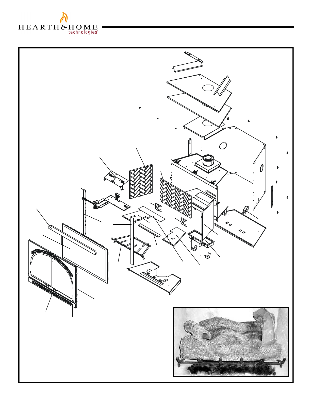
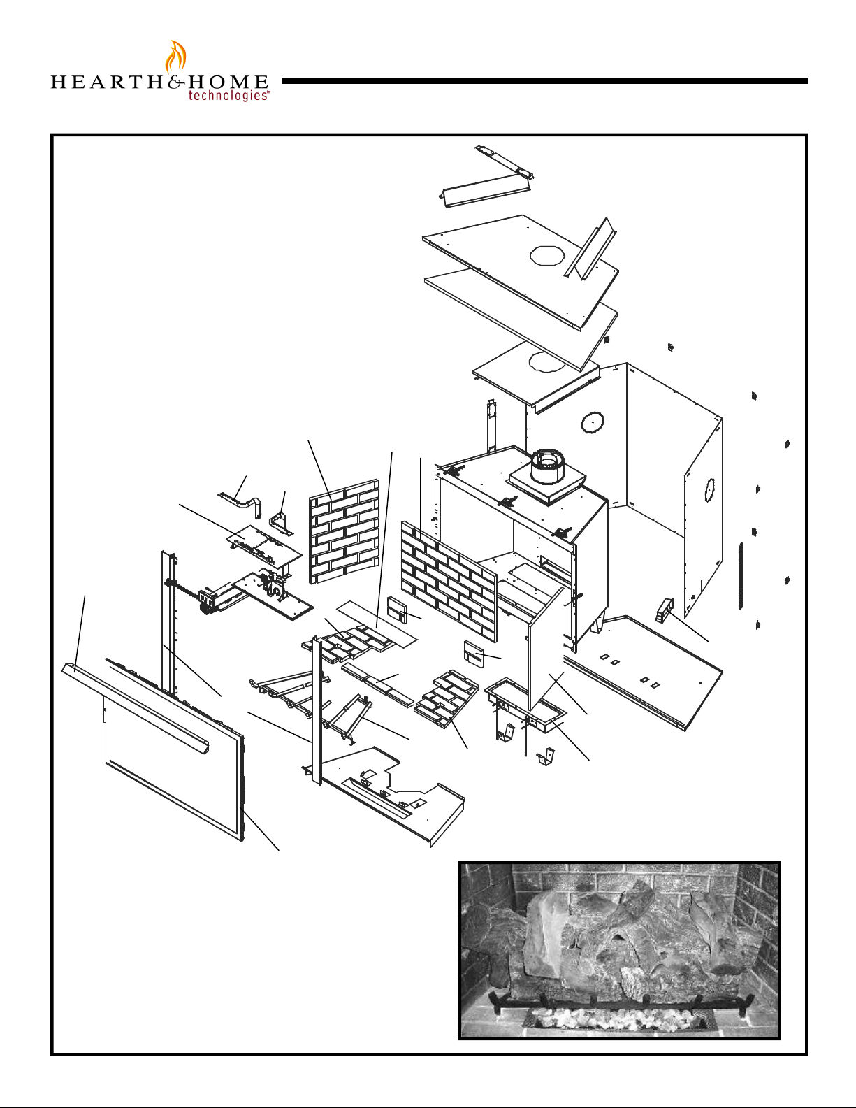
Service Parts
TIT AN
u
(NG, LP) Exploded Parts Diagram
(GN, PL) Vue éclatée des pièces
3
1
Beginning Manufacturing Date: 10-03-02
Ending Manufacturing Date: 2-01-05
4
11
12
24
25
13
23
22
6
8
10
7
5
14
2
9
15 Log Set Assembly
19
20
26
16
21
18
Part number list on following page.
*
La liste des numéros de pièce se trouve à la page
*
suivante.
17
4
Page 5

(NG, LP) Service Parts List / (GN, PL) Liste des pièces de rechange
TITAN
IMPORTANT: THIS IS DATED INFORMA TION. The most current information is located on your dealers VIP site. When ordering,
supply serial and model numbers to ensure correct service parts. / IMPORTANT : L'information fournie dans cette brochure
n'est valide que pendant une courte période. Les sites VIP des distributeurs disposent des renseignements les plus récents.
Lors d'une commande, veuillez fournir les numéros de série et de modèles pour un remplacement adéquat des pièces.
ITEM /
PIÈCE
1
Burner NG / Brûleur GN 781-175A
1 Burner LP / Brûleur PL 781-176A
2
Ember Mesh Screen / Écran 780-382
3 Refractory, Left Side / Réfractairecôté gauche SRV781-735
4
Refractory, Back / Réfractaire arrière SRV781-730
5
Refractory, Right Side / Réfractairecôté droit SRV781-731
6 Refractory, Back Left / Réfractaire arrière gauche SRV781-733
7
Refractory, Back Right / Réfractairearrière droit SRV781-734
8 Refractory, Left Base / Réfractaire Basegauche SRV781-732
9
Refractory, Right Base / Réfractaire Base droit SRV781-736
10 Refractory, Middle Base / Réfractaire Base SRV781-737
11 Hood / Hotte SRV570-143
12
Glass Door Assembly / Porte en verre GLA-780
13 Decorative Front / Avant décoratif DF-TITAN
14
Electric Ember Box / La Boîte Electrique de Braise 780-197A
15 Log Set Assembly / Jeu de Bûches LOGS-TITAN
16
Log 1 / Bûche 1 SRV781-701
17
Log 2 / Bûche 2 SRV781-702
18 Log 3 / Bûche 3 SRV781-703
19
Log 4 / Bûche 4 SRV781-704
20 Log 5 / Bûche 5 SRV781-706
21
Log 6 / Bûche 6 SRV781-705
22 Log Grate / Grille de Bûche 781-360A
23 Side Panel (Order as custom overlay, reference: 780-130) N/A
24
Black Handles Assembly / L'Assemblée noire de Poignées 060-024A-BK
25 Louver / Louvre 781-144
26
Junction Box - IPI / Boîtier de raccordement - IPI 383-250A
IPI IGNITION / ALLUMAGE IPI
SERIAL #
/ N° DE SÉRIE
PART NUMBER
/ N° DE PIÈCE
Lava Rock Bag / Le Sac de Rocher de lave 705-420
Light Socket Assembly / L'Assemblée légère de Douille 700-108A
Refractory Bracket / Crochet réfractaire 780-198
51 inch Wire Harness / Harnais de fil 065-577A
Wire Assembly / Module de fil 505-501A
Ember Reflector / Réflecteur de braise 430-602
Cord Assembly / Assemblée de corde 700-550A
Mineral Wool / Laine minérale 050-721
T-Handle / T-Poignée 567-313
ACCESSORIES / ACCESSOIRES
Remote Control Kit / Module de commande à distance RC-SMART-HTL
Remote Control Kit / Module de commande à distance SMART-STAT-HTL
Remote Control Kit / Module de commande à distance RCT-MLT-HTL
Wall Switch Kit / Interrupteur mural WSK-MLT
Wall Switch Kit, Off-white / Interrupteur mural, blanc crème WSK-21
Wall Switch Kit, White / Interrupteur mural, blanc WSK-21-W
Conversion Kit NG / Module de conversion GN NGK-TITAN
Conversion Kit LP / Module de conversion PL LPK-TITAN
Fan Kit* / Module de ventilateur* GFK-160A
u
u
u
u
u
u
u
Also see following pages for additional valve assembly service part numbers.
NOTE: Replacement bulbs to be supplied by homeowner. Recommended replacements: Sylvania Mini Candelabra 75 watts.
See Section 4: Maintaining and Servicing your Fireplace for instructions.
* In order to operate the fan kit, the fireplace must have either the WSK-MLT wall switch or RCT-MLT-HTL remote kit.
5
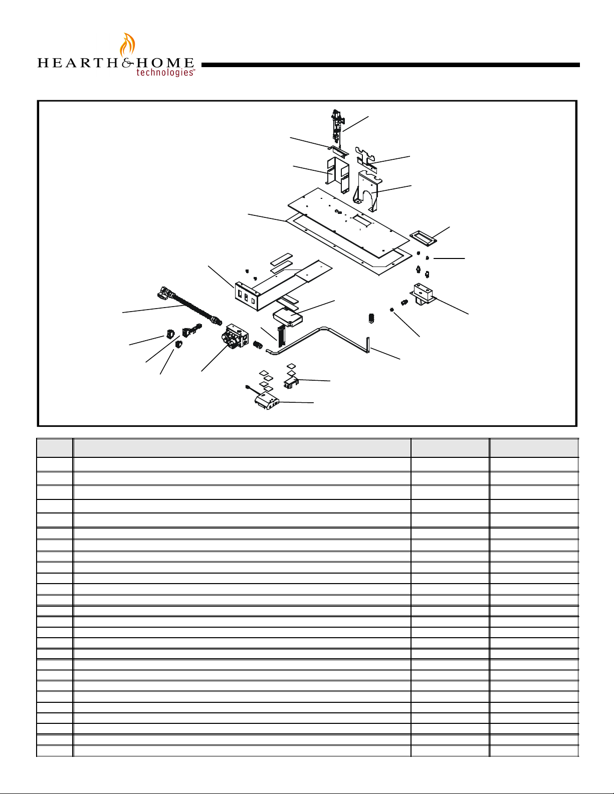
Page 6
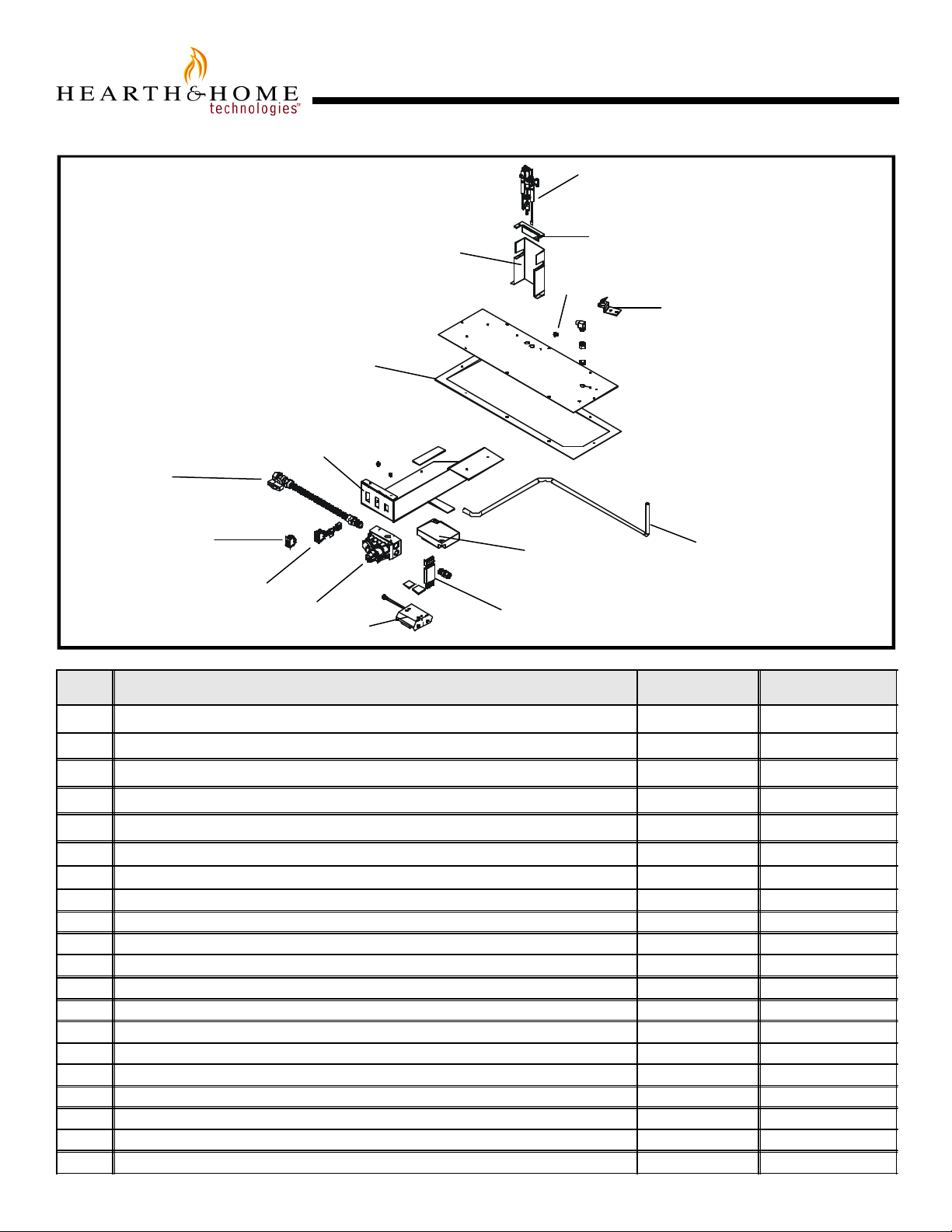
Service Parts
TIT AN
(NG, LP) Exploded Parts Diagram
(GN, PL) Vue éclatée des pièces
Intermittent Pilot Ignition
Valve Assembly
5
7
3
12
1
10
Beginning Manufacturing Date: 10/02
Ending Manufacturing Date: 2/1/04
4
14
13
15
9
2
8
11
6
ITEM /
PIÈCE
1 Pilot Bracket / Parenthèse Pilote 781-164
2 ON/OFF Rocker Switch / Interrupteur à bascule MARCHE/ARRÊT 060-521A
3 ON/OFF Rocker Switch / Interrupteur à bascule MARCHE/ARRÊT 060-511
4 Pilot Assembly NG / Module de veilleuse GN 385-510A
4 Pilot Assembly LP / Module de veilleuse PL 385-511A
5 Valve Bracket / Parenthèse de Valve 780-145
6 Battery Pack / Paquet de Batterie(Pile) 593-594A
7 Flex Ball Valve Assembly / Fléchir l'Assemblée de Soupape de Balle 302-320A
8 Valve NG / Valve GN 750-500
8 Valve LP / Valve PL 750-501
9 Flexible Gas Connector / Tuyau à gaz flexible 570-302A
10 Module / Module 593-592
11 Wire Assembly / Module de fil 593-590A
12 Valve Plate Gasket / Joint de Plat de Valve 780-431
13 Orifice Assembly NG (#26C) / Assemblée d'Orifice GN (#26C) 582-826
13 Orifice Assembly LP (#45C) / Assemblée d'Orifice PL (#45C) 582-845
14 Pilot Assembly Support / Appui d'Assemblée Pilote 397-121
15 Orifice Bracket / Parenthèse d'Orifice 781-165
Ground Strap / Courroie de Raison(Terre) 385-512
3 Volt Transformer / 3 Transformateur de Volt 593-593A
DESCRIPTION
SERIAL #
/ N° DE SÉRIE
PART NUMBER
/ N° DE PIÈCE
u
u
u
6
Page 7
Service Parts
OLYMPUS
u
1
20
(NG, LP) Exploded Parts Diagram
(GN, PL) Vue éclatée des pièces
3
2
3
21
Beginning Manufacturing Date: 10-02
Ending Manufacturing Date: _______
7
4
9
8
Part number list on following page.
*
La liste des numéros de pièce se trouve à la page
*
suivante.
4
6
3
3
4
10 Log Set Assembly
12
13
16
3
5
18
15
22
19
17
11
14
7
Page 8

(NG, LP) Service Parts List / (GN, PL) Liste des pièces de rechange
u
OLYMPUS
IMPORTANT: THIS IS DATED INFORMA TION. The most current information is located on your dealers VIP site. When ordering,
supply serial and model numbers to ensure correct service parts. / IMPORTANT : L'information fournie dans cette brochure
n'est valide que pendant une courte période. Les sites VIP des distributeurs disposent des renseignements les plus récents.
Lors d'une commande, veuillez fournir les numéros de série et de modèles pour un remplacement adéquat des pièces.
ITEM /
PIÈCE
1 Burner LP / Brûleur PL 780-175A
1 Burner NG / Brûleur GN 780-176A
2 Ember Mesh Screen / Écran 780-382
3
Sides and Back Refractory / Réfractairecôté et arrière SRV780-730A
4 Base Refractory Assembly / Model de réfractaire Base SRV780-732A
5 Electric Ember Box / La Boîte Electrique de Braise 780-197A
6
Log Grate / Grille de Bûche 780-360A
7 Hood / Hotte SRV570-143
8 Glass Door Assembly / Porte en verre GLA-780
9
Side Panel (Order as custom overlay, reference: 780-130) N/A
10 Log Set Assembly / Jeu de Bûches LOGS-OLY
11 Log 1 / Bûche 1 SRV780-701
12
Log 2 / Bûche 2 SRV780-702
13 Log 3 / Bûche 3 SRV780-703
14 Log 4 / Bûche 4 SRV780-704
15
Log 5 / Bûche 5 SRV780-705
16 Log 6 / Bûche 6 SRV780-706
17 Log 7 / Bûche 7 SRV780-707
18
Log 8 / Bûche 8 SRV780-708
19 Log 9 / Bûche 9 SRV780-709
20 Left NG Burner Tube / Tube de brûleur gauche GN 780-300A
20 Left LP Burner Tube / Tube de brûleur gauche PL 780-302A
21 Right NG Burner Tube / Tube de brûleur droite GN 780-301A
21
Right LP Burner Tube / Tube de brûleur droite PL 780-303A
22
Junction Box - IPI / Boîtier de raccordement - IPI 383-250A
IPI IGNITION / ALLUMAGE IPI
SERIAL #
/ N° DE SÉRIE
PART NUMBER
/ N° DE PIÈCE
Lava Rock Bag / Le Sac de Rocher de lave 705-420
Light Socket Assembly / L'Assemblée légère de Douille 700-108A
Refractory Bracket / Crochet réfractaire 780-198
51 inch Wire Harness / Harnais de fil 065-577A
Wire Assembly / Module de fil 505-501A
Ember Reflector / Réflecteur de braise 430-602
Cord Assembly / Assemblée de corde 700-550A
Mineral Wool / Laine minérale 050-721
T-Handle / T-Poignée 567-313
Golden Embers / Braises dorées GE-93
ACCESSORIES / ACCESSOIRES
Remote Control Kit / Module de commande à distance RC-SMART-HNG
Remote Control Kit / Module de commande à distance SMART-STAT-HNG
Remote Control Kit / Module de commande à distance RCT-MLT-HNG
Wall Switch Kit / Interrupteur mural, WSK-MLT
Wall Switch Kit, Off-white / Interrupteur mural, blanc crème WSK-21
Wall Switch Kit, White / Interrupteur mural, blanc WSK-21-W
Conversion Kit NG / Module de conversion GN NGK-OLY
Conversion Kit LP / Module de conversion PL LPK-OLY
Fan Kit * / Module de ventilateur* GFK-160A
u
u
u
u
u
u
u
u
Also see following pages for additional valve assembly service part numbers.
NOTE: Replacement bulbs to be supplied by homeowner. Recommended replacements: Sylvania Mini Candelabra 75 watts.
See Section 4: Maintaining and Servicing your Fireplace for instructions.
* In order to operate the fan kit, the fireplace must have either the WSK-MLT wall switch or RCT-MLT-HNG remote kit.
8
Page 9
Service Parts
OLYMPUS
u
Intermittent Pilot Ignition
Valve Assembly
7
3
2
1
(NG, LP) Exploded Parts Diagram
(GN, PL) Vue éclatée des pièces
21
17
14
5
11
8
6
Beginning Manufacturing Date: 10/02
Ending Manufacturing Date: _______
4
19
18
13
15
10
12
16
9
20
ITEM /
PIÈCE
1 Switch Assembly, Solenoid / Changer l'Assemblée, le Solénoïde 386-520A
2 ON/OFF Rocker Switch / Interrupteur à bascule MARCHE/ARRÊT 060-521A
3 ON/OFF Rocker Switch / Interrupteur à bascule MARCHE/ARRÊT 060-511
4 Pilot Assembly NG / Module de veilleuse GN 385-510A
4 Pilot Assembly LP / Module de veilleuse PL 385-511A
5 Valve Bracket / Parenthèse de Valve 780-145
6 Battery Pack / Paquet de Batterie(Pile) 593-594A
7 Flex Ball Valve Assembly / Fléchir l'Assemblée de Soupape de Balle 302-320A
8 Valve NG / Valve GN 593-500
8 Valve LP / Valve PL 593-501
9 Flexible Gas Connector / Tuyau à gaz flexible 570-302A
10 Module / Module 593-592
11 Wire Assembly / Module de fil 593-590A
12 Manifold Assembly / L'Assemblée diverse 386-301A
13 Manifold Gasket /Joint Diversifié(Varié) 385-410
14 Valve Plate Gasket / Joint de Plat de Valve 780-431
15 Orifice Assembly NG (#46C) (Requires 2) / Assemblée d'Orifice GN (#46C) 582-846
15 Orifice Assembly LP (#62C) (Requires 2) / Assemblée d'Orifice PL (#62C) 582-862
16 Orifice Assembly NG (#35C) / Assemblée d'Orifice GN (#35C) 582-835
16 Orifice Assembly LP (#51C) / Assemblée d'Orifice PL (#51C) 582-851
17 Pilot Bracket / Parenthèse Pilote 780-164
18 Burner Tube Bracket / Le Crochet de Tube de brûleur 780-149
19 Burner Tube Bracket / Le Crochet de Tube de brûleur 780-147
20 9 Volt Battery Holder / 9 Porte-Pile de Volt 386-511
21 Pilot Assembly Support / Appui d'Assemblée Pilote 397-121
3 Volt Transformer / 3 Transformateur de Volt 593-593A
DESCRIPTION
SERIAL #
/ N° DE SÉRIE
PART NUMBER
/ N° DE PIÈCE
u
u
u
u
9
Page 10

1
Approvals and
Codes
Appliance Certification
The Hearth & Home Technologies fireplace models
discussed in this Installers Guide have been tested to
certification standards and listed by the applicable
laboratories.
Certification
MODELS: Olympus, Titan
LABORATORY: Underwriters Laboratories
TYPE: Vented Gas Fireplace Heater
STANDARD: ANSI Z21.88•CGA2.22•UL307B
Installation Codes
The fireplace installation must conform to local codes. Before
installing the fireplace, consult the local building code
agency to ensure that you are in compliance with all
applicable codes, including permits and inspections.
In the absence of local codes, the fireplace installation must
conform to the National Fuel Gas Code ANSI Z223.1 (in
the United States) or the CAN/CGA-B149 Installation Codes
(in Canada). The appliance must be electrically grounded
in accordance with local codes or, in the absence of local
codes with the National Electric Code ANSI/NFPA No. 70
(in the United States), or to the CSA C22.1 Canadian Electric
Code (in Canada).
High Altitude Installations
U.L. Listed gas appliances are tested and approved without requiring changes for elevations from 0 to 2,000 feet in
the U. S. A. and in Canada.
When installing this appliance at an elevation above 2,000
feet, it may be necessary to decrease the input rating by
changing the existing burner orifice to a smaller size. Input
rate should be reduced by 4% for each 1000 feet above a
2000 foot elevation in the U.S.A. or 10% for elevations
between 2000 and 4500 feet in Canada. If the heating value
of the gas has been reduced, these rules do not apply. To
identify the proper orifice size, check with the local gas
utility.
If installing this appliance at an elevation above 4,500 feet
(in Canada), check with local authorities.
These models may be installed in a bedroom or bed-sitting
room in the U.S.A. and Canada.
10
Page 11

2
Getting Started
Introducing the Hearth & Home Technologies
Gas Fireplaces
Hearth & Home Technologies direct vent gas fireplaces are
designed to operate with all combustion air siphoned from
outside of the building and all exhaust gases expelled to
the outside.
The information contained in this Installers Guide, unless
noted otherwise, applies to all models and gas control
systems. Gas fireplace diagrams, including the dimensions,
are shown in this section.
Pre-install Preparation
This gas fireplace and its components are tested and safe
when installed in accordance with this Installers Guide.
Report to your dealer any parts damaged in shipment,
particularly the condition of the glass. Do not install any
unit with damaged, incomplete, or substitute parts.
The vent system components are shipped in separate
packages. The gas logs are packaged separately and must
be field installed.
Read all of the instructions before starting the
installation. Follow these instructions carefully during
the installation to ensure maximum safety and benefit.
Failure to follow these instructions will void the
owner’s warranty and may present a fire hazard.
The Hearth & Home Technologies Warranty will be voided
by, and Hearth & Home Technologies disclaims any
responsibility for, the following actions:
• Installation of any damaged fireplace or vent system
component.
• Modification of the fireplace or direct vent system.
• Installation other than as instructed by Hearth & Home
Technologies.
• Improper positioning of the gas logs or the glass door.
• Installation and/or use of any component part not manufactured and approved by Hearth & Home Technologies,
not withstanding any independent testing laboratory or
other party approval of such component part or accessory.
ANY SUCH ACTION MAY POSSIBLY CAUSE A FIRE
HAZARD.
When planning a fireplace installation, it’s necessary to
determine:
• Where the unit is to be installed.
• The vent system configuration to be used.
• Gas supply piping.
• Electrical wiring.
• Framing and finishing details.
• Whether optional accessories—devices such as a fan,
wall switch or remote control —are desired.
If the fireplace is to be installed on carpeting or tile, or on
any combustible material other than wood flooring, the
fireplace should be installed on a metal or wood panel that
extends the full width and depth of the fireplace.
11
Page 12

Dimensions in inches.
34-1/16
(203mm)
(636mm)
16-7/16
(417mm)
(1196mm)
ELECTRICAL
Dimensions in brackets are millimeters.
17-1/8
(434mm)
(866mm)
1/2
(13mm)
GAS LINE
ACCESS
24-5/8
(625mm)
2-13/16
(71mm)
7-1/8
(181mm)
50-1/2
(1283mm)
56-1/4
(1428mm)
Ø8
(1107mm)
41-3/8
(1051mm)
43-5/8
5-11/16
(144mm)
25-1/8
47-1/8
2-5/16
(58mm)
ACCESS
NAILING
TABS
GAS LINE
ACCESS
GAS CONTROLS
TOP STANDOFFS
HOOD
RATING PLATES
AND LABELS
ELECTRICAL
ACCESS
Figure 1. Diagram of Titan
12
Page 13

34-3/16
(625mm)
16-7/16
(417mm)
8 (203mm)
ELECTRICAL
(1196mm)
Dimensions in inches.
GAS LINE
ACCESS
7-1/8
(181mm)
25-1/8
(638mm)
2-13/16
(71mm)
17-1/8
(435mm)
(868mm)
50-1/2
(1283mm)
56-1/4
(1428mm)
1/2
(13mm)
24-5/8
Ø
43-5/8
41-3/8
(1052mm)
(1107mm)
5-11/16
(144mm)
2-5/16
(58mm)
47-1/8
ACCESS
NAILING
TABS
GAS LINE
ACCESS
GAS CONTROLS
TOP STANDOFFS
HOOD
RATING PLATES
AND LABELS
ELECTRICAL
ACCESS
Figure 2. Diagram of Olympus
13
Page 14

Installing the Fireplace
D
4“ (102mm)
3
Step 1. Locating the Fireplace
The diagram below shows space and clearance requirements for locating a fireplace within a room.
E
C
A
The distance from the unit to combustible construction
is to be measured from the unit outer wrap surface to
the combustible construction, NOT from the screw
heads that secure the unit together.
Minimum Clearances
from the Vent Pipe to Combustible Materials
Inches mm
Vertical Sections. ............. 1 ............... 25
B
A B C D E
57 1/2” 25 5/8” 42 1/4” 59 3/4” 84 1/2”
(1460mm) (651mm) (1073mm) (1518mm) (2147mm)
Figure 3. Fireplace Dimensions, Locations,
and Space Requirements
Clearance Requirements
The top, back, and sides of the fireplace are defined by
stand-offs. The minimum clearance to a perpendicular wall
extending past the face of the fireplace is 4 inches (102
mm). The back of the fireplace may be recessed 25 1/8
inches (638mm) into combustible construction.
Minimum Clearances
from the Fireplace to Combustible Materials
Inches mm
Glass Front ...................... 36.................... 914
Floor ................................. 0 ......................0
Rear ................................1/2 ....................13
Sides ...............................1/2 ....................13
Top ................................. 3 1/2...................89
Ceiling* ............................ 31.................... 787
Horizontal Sections
Top ................................3*............... 75
Bottom............................ 1 ............... 25
Sides .............................. 1 ............... 25
At Wall Firestops
Top ................................. 3 ............... 75
Bottom............................ 1 ............... 25
Sides .............................. 1 ............... 25
* When using DVP-Series pipe additional clearance and/or
installation of a heat shield is required above the first 90°
elbow (see Figure 4).
For minimum clearances of direct vent termination see
Figures 21 and 22.
* The clearance to the ceiling is measured from the top
of the unit, excluding the standoffs (see Figure 26).
14
Page 15

E
CAB
NOTE: When venting with a 3 foot vertical and 900 elbow as
3 INCHES
the first two vent components, the non-combustible zone
is the entire width and depth of the firebox from the top of
the fireplace to 3” above the horizontal vent. This area
must remain free of combustibles (see Figure 4).
WALL STUD
STARTER ELBOW
(DVP90ST)
Step 2. Framing the Fireplace
Fireplace framing can be built before or after the fireplace is
set in place. Framing should be positioned to accommodate wall coverings and fireplace facing material. The diagram below shows framing reference dimensions.
CAUTION: MEASURE FIREPLACE DIMENSIONS AND
VERIFY FRAMING METHODS AND WALL COVERING
DETAILS BEFORE FRAMING.
Shows center of framing hole for venting. The center of the hole is one (1)
inch above the center of the horizontal vent pipe.
The framing
headers may
10”
12”
D
rest on the
fireplace
stand-offs.
Figure 4. Non-combustible zone
Framing should
be constructed
of 2 X 4 lumber
or heavier.
A. ...........................57 1/2”
B.............................47 5/8”
C. ...........................25 5/8”
D.............................89 3/8”
E . ............................88 3/8”
Figure 5. Framing Dimensions
15
Page 16

DVP90ST
12-9/16
12-3/16
MAX.
DVP12
12
2
MIN.
6
4
DVP4
DVP6
14-1/4
24
9-7/8
DVP12A
10-1/4
DVP45
45.0
36
48
O
DVP24
DVP36
11-1/4
7-1/4
1-1/4 TYP
DVP48
1/2 TYP8-9/16
NOTE: PIPES OVERLAP 1-1/4 INCHES
(34.93mm) AT EACH JOINT.
Figure 6. DVP-Series Direct Vent Component Specifications (5-inch inner pipe / 8-inch outer pipe)
16
Page 17

Step 3. Installing the Vent System
HEAT SHIELD
WALL FIRESTOP
A. Vent System Approvals
The Titan and Olympus models are approved to use DVPseries vent pipe components (Figures 6 and 7) and terminations. Approved vent system components are labeled for
identification. This pipe is tested and listed as an approved
component of the fireplace. The pipe is tested to be run
inside an enclosed wall. There is no requirement for inspection openings at each joint within the wall. There is no
required pitch for horizontal vent runs. NO OTHER VENT-
ING SYSTEMS OR COMPONENTS MAY BE USED.
Detailed installation instructions are included with each vent
termination kit and should be used in conjunction with this
Installers Guide.
The flame and ember appearance may vary based on the type
of fuel burned and the venting configuration used.
Vent Components
VERTICAL
TERMINATION
Identifying Vent Components
The vent systems installed on this gas fireplace may include one, two or three 90° elbow assemblies. The relationships of vertical rise to horizontal run in vent configurations
using 90° elbows MUST BE strictly adhered to. The rise to
run relationships are shown in the venting drawings and
tables. Refer to the diagrams on the next several pages.
NOTE: Two 45° elbows may be used in place of one
90° elbow. Rise to run ratios in the vent system must
be followed if 45° elbows are used.
WARNING: A 3-FOOT LENGTH OF STRAIGHT
!
PIPE (MINIMUM) MUST BE THE FIRST VENT
COMPONENT ATTACHED TO THE UNIT.
STORM COLLAR
ROOF FLASHING
HORIZONTAL
TERMINATION
Vent Termination Components
DVP-TV
DVP-TVHW
90 DEGREE
ELBOW
CEILING
FIRESTOP
PIPE LENGTH
Figure 7. Vent Components and Termination Kits
DVP-TRAP SERIES
PVK-80
17
Page 18

STRAIGHT UP
V
H
V
VERTICAL VENTING
V (FT.)
40' MAX. (12.2 M)
3' MIN. (0.9 M)
CAP
Figure 8. Straight Up Vertical Venting
VENTING WITH ONE (1) 90° ELBOW NG
V (FT.) H (FT.)
3' MIN. (914 mm) 6' MAX. (1.9m)
4' MIN. (1.2m) 8' MAX. (2.4m)
5' MIN. (1.6m) 10' MAX. (3.1m)
6' MIN. (1.9m) 12' MAX. (3.6m)
V + H = 30’ MAX. (9.3 m)
Ratio V to H = 1:2
H = 20' MAX. (6.2m)
Note: When venting with LP on Olympus
the V to H ratio is 1:1, and H = 15’ MAX.
Figure 9. Venting with One 90° Elbow
18
Page 19

VENTING WITH TWO (2) 90° ELBOWS NG
V
H
H1H
V
V (FT.) *H (FT.)
3' MIN. (914mm) 6' MAX. (1.9m)
4' MIN. (1.2m) 8' MAX. (2.4m)
5' MIN. (1.6m) 10' MAX. (3.1m)
6' MIN. (1.9m) 12' MAX. (3.6m)
*
V + H + H1 = 30’ MAX. (9.3 m)
Ratio V to H + H1 = 1:2
H = 20' MAX. (6.2m)
Note: When venting with LP on Olympus
the V to H ratio is 1:1, and H = 15’ MAX.
VENTING WITH TWO (2) 90° ELBOWS NG
*Note: When a 900 elbow is
placed in a horizontal position it
counts as 3 feet of horizontal.
V
1
V (FT.) H (FT.)
3' MIN. (914 mm) 6' MAX. (1.9m)
4' MIN. (1.2m) 8' MAX. (2.4m)
5' MIN. (1.6m) 10' MAX. (3.1m)
6' MIN. (1.9m) 12' MAX. (3.6m)
V + V1 + H1 = 30’ MAX. (9.3 m)
Ratio V to H = 1:2
H = 20' MAX. (6.2m)
Note: When venting with LP on Olympus
the V to H ratio is 1:1, and H = 15’ MAX.
Figure 10. Venting with two 90° elbows
u
19
Page 20

VENTING WITH THREE (3) 90° ELBOWS NG
VHH
1
V (FT.) H (FT.)
3' MINIMUM (914 mm) 6' MAXIMUM (1.9 m)
4' MINIMUM (1.2 m) 8' MAXIMUM (2.4 m)
5' MINIMUM (1.6 m) 10' MAXIMUM (3.1 m)
RATIO V TO H = 1:2
V + V1 + H + H1 = 30’ MAXIMUM (9.3m)
H + H1 = 20’ MAXIMUM (6.2m)
H = 10’ MAXIMUM (3.1m)
Note: When venting with LP on Olympus
the V to H ratio is 1:1, and H = 15’ MAX.
H
1
V
1
V
H
V
1
*Note: When a 900 elbow is placed in a horizontal position it counts as 3 feet of horizontal. Also when venting with three 900 elbows only one 900 elbow may be placed in
a horizontal position.
VENTING WITH THREE (3) 90° ELBOWS NG
V (FT.) *H + H1 (FT.)
3' MINIMUM (914 mm) 6' MAXIMUM (1.9 m)
4' MINIMUM (1.2 m) 8' MAXIMUM (2.4 m)
5' MINIMUM (1.6 m) 10' MAXIMUM (3.1 m)
6' MINIMUM (1.9 m) 12' MAXIMUM (3.6 m)
V + V1 + H + H1 = 30’ MAXIMUM (9.3 m)
H + H1 = 20’ MAXIMUM (6.2 m)
RATIO V TO H + H1 = 1:2
*
Note: When venting with LP on Olympus
the V to H ratio is 1:1, and H = 15’ MAX.
Figure 1 1. Venting with three 90° elbows
u
20
Page 21

EXTERIOR
FIRESTOP
B. Installing Vent Components
10"
12"
1. Attaching the Venting to the Fireplace
Refer to Cinch Pipe and Termination Cap installation instructions.
2. Assembling Vent Sections
Refer to Cinch Pipe and Termination Cap installation instructions.
If the installation is for a termination cap attached directly
to the fireplace, skip to the sections, Install Firestops and
Vent Termination.
• Continue adding vent components, locking each succeeding component into place.
• Ensure that each succeeding vent component is securely fitted and locked into the preceding component in the
vent system.
• 90° elbows may be installed and rotated to any point
around the preceding component’s vertical axis. If an elbow does not end up in a locked position with the preceding component, attach with a minimum of two (2)
sheet metal screws.
3. Install Support Brackets
Refer to Cinch Pipe and Termination Cap installation instructions.
INTERIOR
WALL SHIELD
Figure 12. 10" x 12" Hole and Vent Pipe
HEAT SHIELD
INTERIOR
FIRESTOP
Trim Heat Shield
if too long, add to
Heat Shield if too short.
4. Install Firestops
For Horizontal Runs - Firestops are REQUIRED on both
sides of a combustible wall through which the vent passes.
NOTE: Model DVP-TRAP does not need an exterior
firestop on an exterior combustible wall.
To install firestops for horizontal runs that pass through
either interior or exterior walls:
• Cut a 10-inch by 12-inch (245mm x 305mm) hole through
the wall.
NOTE: The center of the hole is one (1) inch (25.4mm)
above the center of the horizontal vent pipe.
• Position the firestops on both sides of the hole previously cut and secure the firestops with nails or screws.
• The heat shields of the firestops MUST BE placed towards the top of the hole.
• Continue the vent run through the firestops.
NOTE: There must be NO INSULATION or other
combustibles inside the framed firestop opening.
Figure 13. Heat Shield, Interior & Exterior Firestops
For Vertical Runs - One ceiling firestop is REQUIRED at
the hole in each ceiling through which the vent passes.
To install firestops for vertical runs that pass through ceilings:
• Position a plumb bob directly over the center of the vertical vent component.
• Mark the ceiling to establish the centerpoint of the vent.
• Drill a hole or drive a nail through this centerpoint.
• Check the floor above for any obstructions, such as wiring or plumbing runs.
• Reposition the fireplace and vent system, if necessary,
to accommodate the ceiling joists and/or obstructions.
• Cut a 10-inch x 10-inch (254mm x 254mm) hole through
the ceiling, using the centerpoint previously marked.
• Frame the hole with framing lumber the same size as the
ceiling joists.
21
Page 22

7 1/4"
(184mm)
JOIST
CEILING
EXISTING CEILING
NOTE: There must be NO INSULATION or other
combustibles inside the framed firestop opening.
C. Vent Termination
Refer to Cinch Pipe and Termination Cap installation instructions.
10" (254mm)
10" (254mm)
CHIMNEY
HOLE
CEILING
NEW
FRAMING
MEMBERS
JOISTS
Figure 14. 10" x 10" Hole and New
Framing Members
If the area above the ceiling is NOT an attic, position and
secure the ceiling firestop on the ceiling side of the previously
cut and framed hole.
WARNING: THE TERMINA TION CAP MUST BE
POSITIONED SO THA T THE ARROW IS POINT -
!
ING UP.
WARNING: VENTING TERMINALS SHALL
!
NOT BE RECESSED INTO A WALL OR SIDING. VENT TERMINATION CLEARANCES MUST
BE FOLLOWED TO A VOID FIRE DANGER. SEE
VENT TERMINA TION MINIMUM CLEARANCES DIAGRAM ON FOLLOWING PAGE.
Horizontal terminations require insulation (included with the
fireplace) to be placed directly above the heatshield on DVPTR termination kit. Failure to correctly install this insulation
could possibly result in a fire hazard.
PLACE INSULATION
HERE
CEILING
NAILS
FIRESTOP
Figure 15. Ceiling Firestop (Ceiling Side)
If the area above the ceiling IS an attic, position and secure
the firestop on top of the previously framed hole.
NOTE: Keep insulation away from the vent pipe at least
1 inch (25mm).
NAILS
RAFTER
CEILING
CEILING FIRESTOP
Figure 17. Titan Only: Horizontal Termination
Figure 18. Trapezoid Termination Cap
Figure 16. Attic Firestop
22
Page 23

v
AHMXJ or K
I
A
G
U.S.
(3 FT)
B
M
Q
Electrical
D*
V
N
v
D
E
v
B
L
v
= VENT TERMINAL X
V
B
v
F
v
v
B
v
= AIR SUPPLY INLET = AREA WHERE TERMINAL IS NOT PERMITTED
A = 12".......................... clearances above grade, veran-
(See Note 1)
da, porch, deck or balcony
B = 12".......................... clearances to window or door
that may be opened, or to permanently closed window.
D* = 36".......................... vertical clearance to unventilat-
ed soffit or to ventilated soffit located above the terminal
*60” ......................... for vinyl clad soffits and below
electrical service
F = 9" ........................... clearance to outside corner
G = 6" ............................ clearance to inside corner
H = 3 ft. (Canada) ....... not to be installed above a gas
meter/regulator assembly within
3 feet (90cm) horizontally from the
center-line of the regulator
I = 3 ft. (U.S.A.)
6 ft. (Canada) ....... clearance to gas service regu-
lator vent outlet
J = 9" (U.S.A.)
12" (Canada) ......... clearance to non-mechanical air
supply inlet to building or the
combustion air inlet to any other
appliance
R
P
(See Note 2)
S
V
V
T
S
Service
V
K = 3 ft. (U.S.A.)
6 ft. (Canada) .......... clearance to a mechanical
air supply inlet
L** = 7 ft............................. clearance above paved
(See Note 1)
sidewalk or a paved driveway
located on public property
M*** = 36"............................ clearance under veranda,
porch, deck, balcony or overhang
60” ............................ vinyl
N = 6” .............................. non-vinyl sidewalls
12” ............................ vinyl sidewalls
P = 8 ft.
Q
______________________________________________________________________
1 cap 3 feet 2 x Q
______________________________________________________________________
2 caps 6 feet 1 x Q
______________________________________________________________________
3 caps 9 feet 2/3 x Q
______________________________________________________________________
MIN
4 caps 12 feet 1/2 x Q
Q
= # termination caps x 3 R
MIN
= (2 / # termination caps ) x Q
MAX
R
MAX
ACTUAL
ACTUAL
ACTUAL
ACTUAL
ACTUAL
S = 6" ............................. clearance from sides of elec-
(See Note 5)
trical service
T = 12"............................ clearance above electrical
(See Note 5)
service
** a vent shall not terminate directly above a sidewalk or paved
driveway which is located between two single family dwellings
and serves both dwellings.
*** only permitted if veranda, porch, deck or balcony is fully open on
a minimum of 2 sides beneath the floor, or meets Note 2.
NOTE 1: On private property where termination is less than 7 feet
above a sidewalk, driveway, deck, porch, veranda or balcony, use of
a listed cap shield is suggested.
NOTE 2: Termination in an alcove space (spaces open only on one side
and with an overhang) are permitted with the dimensions specified for
vinyl or non-vinyl siding and soffits. 1. There must be 3 feet minimum
between termination caps. 2. All mechanical air intakes within 10 feet
of a termination cap must be a minimum of 3 feet below the termination
cap. 3. All gravity air intakes within 3 feet of a termination cap must be
a minimum of 1 foot below the termination cap.
NOTE 3: Local codes or regulations may require different
clearances.
NOTE 4: Termination caps may be hot. Consider their proximity to
doors or other traffic areas.
NOTE 5: Location of the vent termination must not interfere with
access to the electrical service.
WARNING: In the U.S: Vent system termination is NOT permitted
in screened porches. You must follow side wall, overhang and
ground clearances as stated in the instructions.
In Canada: Vent system termination is NOT permitted in screened
porches. Vent system termination is permitted in porch areas
with two or more sides open. You must follow all side walls,
overhang and ground clearances as stated in the instructions.
Hearth & Home Technologies assumes no responsibility for the
improper performance of the fireplace when the venting system
does not meet these requirements.
Figure 19. Vent Termination Minimum Clearances
u
CAUTION: IF EXTERIOR WALLS ARE FINISHED WITH VINYL SIDING, IT IS SUGGESTED THAT A VINYL PROTECTOR KIT BE
INSTALLED.
23
Page 24

For Vertical Terminations - To locate the vent and install
HORIZONTAL
VERTICAL
12
the vent sections:
• Locate and mark the vent centerpoint on the underside
of the roof, and drive a nail through the centerpoint.
• Make the outline of the roof hole around the centerpoint nail.
• The size of the roof hole framing dimensions depend on the
pitch of the roof. There MUST BE a 1-inch (25.4mm) clearance from the vertical vent pipe to combustible materials.
• Mark the roof hole accordingly.
To seal the roof hole, and to divert rain and snow from the
vent system:
• Attach a flashing to the roof using nails, and use a nonhardening mastic around the edges of the flashing base
where it meets the roof.
• Attach a storm collar over the flashing joint to form a
water-tight seal. Place non-hardening mastic around the
joint, between the storm collar and the vertical pipe.
• Slide termination cap over the end of the vent pipe and
secure with screws.
• Cover the opening of the installed vent pipes.
• Cut and frame the roof hole.
• Use framing lumber the same size as the roof rafters
and install the frame securely. Flashing anchored to the
frame must withstand heavy winds.
• Continue to install concentric vent sections up through
the roof hole (for inside vent installations) or up past the
roof line until you reach the appropriate distance above
the roof (for outside terminations).
WARNING: MAJOR U.S. BUILDING CODES
!
SPECIFY MINIMUM CHIMNEY AND/OR
VENT HEIGHT ABOVE THE ROOF TOP. THESE MINIMUM HEIGHTS ARE NECESSARY IN THE INTEREST OF SAFETY. SEE THE FOLLOWING DIAGRAM
FOR MINIMUM HEIGHTS, PROVIDED THE TERMINA TION CAP IS AT LEAST 20 INCHES FROM A VERTICAL WALL AND 2-FEET BELOW A HORIZONT AL
OVERHANG .
NOTE: This also pertains to vertical vent systems installed on the outside of the building.
2 FT.
MIN.
TERMINATION
CAP
20 INCH MIN.
LOWEST
DISCHARGE
OPENING
H (MIN.) - MINIMUM HEIGHT FROM ROOF
TO LOWEST DISCHARGE OPENING
Roof Pitch H (min.) ft.
flat to 6/12 1.0
6/12 to 7/12 1.25
over 7/12 to 8/12 1.5
over 8/12 to 9/12 2.0
over 9/12 to 10/12 2.5
over 10/12 to 11/12 3.25
over 11/12 to 12/12 4.0
over 12/12 to 14/12 5.0
over 14/12 to 16/12 6.0
over 16/12 to 18/12 7.0
over 18/12 to 20/12 7.5
over 20/12 to 21/12 8.0
OVERHANG
WALL
X
ROOF PITCH
IS X/ 12
Figure 20. Minimum Height from Roof to
Lowest Discharge Opening
24
Page 25

Step 4. Positioning, Leveling, and
Securing the Fireplace
The diagram below shows how to properly position, level,
and secure the fireplace.
NAILING TABS
(BOTH SIDES)
Step 5. The Gas Control System
WARNING: THIS UNIT IS NOT FOR USE WITH
!
SOLID FUEL.
Intermittent Pilot Ignition (IPI) System
The gas control system used with this model is Intermittent
Pilot Ignition (IPI). This system includes a 3V control valve,
electronic module, and intermittent pilot.
WARNING: CONTINUOUS 110-120 VAC
!
SERVICE MUST BE WIRED DIRECTLY TO
THE FIREPLACE JUNCTION BOX.
NOTE: Flames too close to the ceramic insulators can
cause nuisance lockouts and electrode failure.
Figure 21. Proper Positioning, Leveling, and
Securing of a Fireplace
• Place the fireplace into position.
• Level the fireplace from side to side and from front to
back.
• Shim the fireplace with non-combustible material, such
as sheet metal, as necessary.
• Secure the fireplace to the framing by driving nails or
screws through the nailing tabs.
Figure 22. Gas Control System
25
Page 26

Step 6. The Gas Supply Line
OLYMPUS
TITAN
NOTE: Have the gas supply line installed in accordance
with local building codes by a qualified installer
approved and/or licensed as required by the locality.
(In the Commonwealth of Massachusetts installation
must be performed by a licensed plumber or gas fitter).
NOTE: Before the first firing of the fireplace, the gas
supply line should be purged of any trapped air.
NOTE: Consult local building codes to properly size
the gas supply line leading to the 1/2 inch
(13 mm) hook-up at the unit.
This gas fireplace is designed to accept a 1/2 inch
(13 mm) gas supply line.
To install the gas supply line:
• A listed (and Commonwealth of Massachusetts approved)
1/2 inch (13mm) tee-handle manual shut-off valve and a
listed flexible gas connector are connected to the 1/2
inch (13mm) inlet of the control valve. NOTE: If substituting for these components, please consult local codes
for compliance.
• Locate the gas line access hole in the outer casing of
the fireplace.
• Insert the gas supply line through the gas line hole, and
connect it to the shut-off valve.
• When attaching the pipe, support the control so that the
lines are not bent or torn.
• After the gas line installation is complete, all connec-
u
tions must be tightened and checked for leaks with a
commercially-available, non-corrosive leak check solution. Be sure to rinse off all leak check solution following
testing.
WARNING: DO NOT USE AN OPEN FLAME
!
TO CHECK FOR GAS LEAKS .
• At the gas line access hole, use insulation to re-pack
the space around the gas pipe.
• Insert insulation from the outside of the fireplace and
pack the insulation tightly to totally seal between the
pipe and the outer casing.
USE A WRENCH
ON SHUT-OFF VALVE
WHEN TIGHTENING
GAS LINE.
Figure 23. Gas Supply Line
Step 7. Gas Pressure Requirements
Pressure requirements for these Hearth & Home Technologies gas fireplaces are shown in the table below.
Pressure Natural Gas Propane
Minimum 5.0 in. w.c. (Olympus) 11.0 inches
Inlet Pressure 7.0 in. w.c. (Titan) w.c.
Maximum Inlet 14.0 inches 14.0 inches
Gas Pressure w.c. w.c.
Manifold 3.5 inches 10.0 inches
Pressure w.c. w.c.
Connections are provided on the front of the gas control
valve for both inlet and manifold pressures. To use these
the valve cover must be removed and the small slotted screw
inside the pressure tap loosened. Manifold pressure should
be checked with main burner turned on and rear log off.
This screw must be retightened carefully after pressure
gauge is removed to avoid a gas leak.
The fireplace and its individual shut-off valve must be
disconnected from the gas supply piping system during
any pressure testing of the system at test pressures in
excess of one-half (1/2) psig (3.5 kPa).
The fireplace must be isolated from the gas supply piping
system by closing its individual shut-off valve during any
pressure testing of the gas supply piping system at test
pressures equal to or less than one-half (1/2) psig (3.5 kPa).
26
Page 27

BATTERY
WHTWHTREDBL
K
GRN
VALVE
OPTIONAL
GROUND
12-10 GA
16-14 GA
BURNER
CONTROL
HEYCO
CONN
BLK
BLK
JUNCTION BOX
120 VAC
ELECTRIC
EMBERS
SCALE 1/2
SCALE 1/2
TRANSFORMER
3 VAC
JUNCTION BOX
REM
WHT
BLK
GRN
HALOGEN
LIGHT (2)
120 VAC
FAN
BRN
BRN
BLK
BLK
BATTERY BACKUP
BLK
WHT
BLK
REM
BLK
OPTIONAL
REMOTE
SCALE 1/4
WHT
FAN
WHT
BLK
EMBER BED
REMOTE
75 WATT MAX
IGNITION MODULE VAC 3
RED
BLK
WHT
BRN
TO
FIREPLACE
CHASSIS
GRN
ORG
Figure 24. Intermittent Pilot Ignition (IPI) Wiring Diagram
Step 8. Wiring the Fireplace
NOTE: Electrical wiring must be installed by a licensed
electrician.
CAUTION: DISCONNECT REMOTE CONTROLS BY UNPLUGGING FROM THE JUNCTION BOX IF ABSENT FOR
EXTENDED TIME PERIODS. THIS WILL PREVENT ACCIDENT AL FIREPLACE OPERATION.
For Intermittent Pilot Ignition (IPI) Wiring
Appliance Requirements
This appliance requires that 110-120 VAC be wired to the
factory installed junction box. Maintain correct polarity when
wiring the junction box.
u
Wire 110V to electrical junction box.
Do NOT wire 110V to valve.
Do NOT wire 110V to wall switch.
• Incorrect wiring will damage millivolt valves.
• Uninterrupted or continuous power is
• Incorrect wiring will override IPI safety lockout and may
cause explosion.
Intensifire Switch (Olympus Only)
This model is equipped with an intensifire switch. This
switch allows you to turn On/Off the rear log burners. The
switch is located on the control panel. Install the 9 volt
battery into the battery holder located in the lower compartment right next to the control panel (see Figure 25).
WARNING
required at all times in IPI system EXCEPT
when using battery back-up.
Remove transformer from shipping position by cutting and
removing cable tie.
Plug transformer into side of junction box.
Optional Accessories
Optional fan and remote control kits require that 110-120
VAC be wired to the factory installed junction box before
the fireplace is permanently installed. Note: Use of the GFK160A fan kit requires either the WSK-MLT wall switch kit,
or the RCT-MLT-HNG (Olympus)/RCT-MLT-HTL (Titan)
remote control kit. The GFK-160A plugs into the remote
control module. The remote control module then plugs into
REM on the junction box.
CAUTION: LABEL ALL WIRES PRIOR TO DISCONNECTION WHEN SERVICING CONTROLS. WIRING ERRORS
CAN CAUSE IMPROPER AND DANGEROUS OPERATION.
VERIFY PROPER OPERATION AFTER SERVICING.
MANIFOLD ASSEMBLY
E
I
T
H
W
HOLDER
R
E
D
B
L
A
C
K
B
L
R
A
C
K
SWITCH
E
D
9 VOLT
Figure 25. Intensifire Switch Wiring Diagram
27
Page 28

Step 9. Finishing
2”3”4”5”6”7”8”9”10”
11”
12”
10”
11”
12”
31”
2”1”CEILING
1/2”(13mm)
1/2”(13mm)
FINISH WALL MATERIAL MAY BE COMBUSTIBLE
Figure 26 shows the minimum vertical and corresponding
maximum horizontal dimensions of fireplace mantels or other
combustible projections above the top front edge of the
fireplace. See Figures 3 and 4 for other fireplace clearances.
Only non-combustible materials may be used to cover the
black fireplace front.
9”
8”
Hearth Extensions
A hearth extension may be desirable for aesthetic reasons.
However, ANSI or CAN/CGA testing standards do not require
hearth extensions for gas fireplace appliances.
Step 10. Installing Trim, Refractory,
Logs and Ember Material
Installing the Trim
Combustible materials may be brought up to the specified
clearances on the side and top front edges of the fireplace,
but MUST NEVER overlap onto the front face. The joints
between the finished wall and the fireplace top and sides
can only be sealed with a 300° F. (149° C) minimum sealant.
WARNING: WHEN FINISHING THE FIREPLACE,
!
NEVER OBSTRUCT OR MODIFY THE AIR INLET/
OUTLET GRILLES IN ANY MANNER.
3”
4”
1”
TOP FRONT EDGE
OF FIREPLACE
7”
6”
5”
Figure 26.
Minimum Vertical and Maximum Horizontal
Dimensions of Combustibles above Fireplace
WARNING: WHEN FINISHING THE FIREPLACE,
!
NEVER OBSTRUCT OR MODIFY THE AIR INLET/
OUTLET GRILLES IN ANY MANNER.
CAUTION: IF JOINTS BETWEEN THE FINISHED WALLS
AND THE FIREPLACE SURROUND (TOP AND SIDES)
ARE SEALED, A 300° F. MINIMUM SEALANT MATERIAL MUST BE USED. THESE JOINTS ARE NOT REQUIRED TO BE SEALED. ONLY NON-COMBUSTIBLE
MATERIAL (USING 300° F. MINIMUM ADHESIVE, IF
NEEDED) CAN BE APPLIED AS FACING TO THE FIREPLACE SURROUND. SEE THE DIAGRAM BELOW.
- TOP AND SIDES
Install optional marble and brass trim surround kits as
desired. Marble, brass, brick, tile, or other non-combustible
materials can be used to cover up the gap between the
sheet rock and the fireplace.
When overlapping on both sides, leave enough space so
decorative door is accessible.
Positioning the Refractory
The refractory has been packaged separately, refer to the
instructions included.
Positioning the Logs
The logs have been packaged separately, refer to the instructions included. Save the log instructions with this
manual.
If sooting occurs, the logs might need to be repositioned
slightly to avoid excessive flame impingement.
Placing the Ember Material
Ember material is shipped with this gas fireplace. To place
the ember material:
• Place dime size pieces of ember material about 1/2 inch
apart near port holes in burner top. Do NOT press embers into burner ports. Care should be taken so that the
ports are not covered.
HIGH TEMPERATURE
(3000 F. 1490 C MIN.) SEAL JOINT
Figure 27. Sealant Material
• Save the remaining ember materials for use during fireplace servicing.
• Use of ember material is optional.
28
Page 29

GLASS
CLIP
ASSEMBLY
I-bolt
Figure 28. Glass Assembly
Step 11. Before Lighting the Fireplace
BEFORE lighting the fireplace, be sure to do the following:
• Remove all paperwork from underneath the fireplace.
• Review all cautions, and Safety and Warnings section
at the beginning of this Installers Guide.
• Double-check the unit for possible gas leaks.
• Double-check the unit for possible obstructions that
could be blocking the vent terminations.
• Double-check for faulty components: Any component
that is found to be faulty MUST BE replaced with an approved component. Tampering with the fireplace components is DANGEROUS and voids all warranties.
A small amount of air will be in the gas supply lines. When
first lighting the fireplace, it will take a few minutes for the
lines to purge themselves of this air. Once the purging is
complete, the fireplace will light and will operate normally.
Subsequent lightings of the fireplace will not require this
purging of air from the gas supply lines, unless the gas
valve has been turned to the OFF position, in which
case the air could have to be purged again.
• Glass can now be reinstalled, followed by glass clips
and I-bolts (see Figure 28). I-bolts can be fastened by
using a special hook tool that is shipped with the fireplace. Finish the installation by installing decorative door.
Note: When removing or replacing the glass, use the special hook tool provided with the fireplace to turn the I-bolts to
a 45O angle for ease of operation. The I-bolts can then be
moved through the slots in the glass frame with the special
hook tool provided. Make sure the I-bolts end up in the orientation shown in Figure 28 when installation is complete.
Glass Specifications
OLYMPUS and TITAN TEMPERED GLASS
Hearth and Home Technologies fireplaces manufactured with
tempered glass may be installed in hazardous locations
such as bathtub enclosures as defined by the CPSC. The
tempered glass has been tested and certified to the requirements of ANSI Z97.1-1984 and CPSC 16 CFR 1202. (Safety
Glazing Certification Council SGCC # 1595 and 1597. Architectural Testing, Inc. Reports 02-31919.01 and 02-
31917.01.)
This statement is in compliance with CPSC 16 CFR Sec-
tion 1201.5 “Certification and labeling requirements” which
refers to 15 USC 2063 stating “…Such certificate shall accompany the product or shall otherwise be furnished to any
distributor or retailer to whom the product is delivered.”
NOTE: The fireplace should be run 3 to 4 hours on the initial
start-up. Turn it off and let it cool completely. Remove and
clean the glass. Replace the glass and run the fireplace for
an additional 8 hours. This will help to cure the products
used in the paint and logs.
During this break-in period it is recommended that some
windows in the house be opened for air circulation. This will
help avoid setting off smoke detectors, and help eliminate
any odors associated with the fireplace’s initial burning.
Some local building codes require the use of tempered glass
with permanent marking in such locations. Glass meeting
this requirement is available from the factory. Please contact your dealer or distributor to order.
29
Page 30

Step 12. Lighting the Fireplace
After reviewing all safety warnings, checking the fireplace for gas leaks, checking that the vent system is unobstructed, and
checking for faulty components, be sure power is on and proceed with lighting fireplace.
FOR YOUR
SAFETY READ
BEFORE LIGHTING
WARNING: IF YOU DO NOT FOLLOW THESE
INSTRUCTIONS EXACTLY, A FIRE OR
EXPLOSION MAY RESULT CAUSING
PROPERTY DAMAGE, PERSONAL INJURY,
OR LOSS OF LIFE.
IPI IGNITION
A. This appliance is equipped with an intermittent pilot
ignition (IPI) device which automatically lights the
burner. Do not try to light the burner by hand.
B. BEFORE OPERATING smell all around the
appliance area for gas. Be sure to smell next to the
floor because some gas is heavier than air and will
settle to the floor.
WHAT TO DO IF YOU SMELL GAS
• Do not try to light any appliance.
• Do not touch any electric switch; do not use any
phone in your building.
• Immediately call your gas supplier from a neighbor’s
phone. Follow the gas supplier's instructions.
• If you cannot reach your gas supplier, call the fire
department.
C. Do not use this appliance if any part has been under
water. Immediately call a qualified service technician
to inspect the appliance and to replace any part of
the control system and any gas control which has
been under water.
LIGHTING
INSTRUCTIONS (IPI)
1. STOP! Read the safety information on page 9 first!
2. Turn off all electric power to the appliance.
3. This appliance is equipped with an ignition device
which automatically lights the burner. Do not try to
light the burner by hand.
GAS
VALVE
4. Wait five (5) minutes to clear out any gas. Then
smell for gas, including near the floor. If you smell
gas, STOP! Follow "B" in the Safety Information located on the previous pages. If you don't smell gas,
go to next step.
5. Turn on all electric power to the appliance.
6 T o light the burner, flip the ON/OFF switch to the
“ON” position. (The ON/OFF switch may include a
wall switch if so equipped).
7. If the appliance will not operate, follow the instructions “To Turn Off Gas to Appliance” and
call your service technician or gas supplier.
TO TURN OFF
GAS TO APPLIANCE
1. Turn off all electric power to the appliance if service is
to be performed.
2. Flip ON/OFF switch to the “OFF” position.
When you light your fireplace for the first time, you may
notice:
• This gas appliance produces heat which does have an
associated odor or smell. If you feel this odor is excessive it may require the initial 3-4 hour continuous burn on
high followed by a second burn of up to 12 hours to fully
drive off any odor from paint and lubricants used in the
manufacturing process. Additionally, for the first few minutes after each lighting, vapor may condense and fog the
glass and flames may be blue. After a few minutes this
moisture will disappear and within 15-30 minutes the flames
should become yellow.
During the break-in period it is recommended that some
windows in the house be opened for air circulation.
This will help avoid setting off smoke detectors, and
help eliminate any odors associated with the fireplace’s
initial burning.
• Noise caused by metal expanding and contracting as it
heats up and cools down, similar to the sound produced
by a furnace or heating duct. This noise does not affect
the operation or longevity of your fireplace.
After the Installation
LEA VE THIS INSTALLATION MANUAL WITH
!
THE APPLIANCE FOR FUTURE REFERENCE.
30
Page 31

4
Maintaining and Servicing Your Fireplace
Fireplace Maintenance
Although the frequency of your fireplace servicing and maintenance will depend on use and the type of installation, you
should have a qualified service technician perform an appliance check-up at the beginning of each heating season.
See the table below for specific guidelines regarding each
fireplace maintenance task.
IMPORTANT: TURN OFF THE GAS BEFORE SERVICING
YOUR FIREPLACE.
Replacing old ember material
Frequency: Once annually, during the checkup.
By: Qualified service technician.
Task: Brush away loose ember material near the burner.
Replace old ember material with new dime-size and shape
pieces of Golden Ember (DE-93) and Glowing Ember (050-
721). Save the remaining ember material and repeat this
procedure at your next servicing. For more information, see
Placing Ember Material.
Cleaning Burner and Controls
Frequency: Once annually.
By: Qualified service technician.
Task: Brush or vacuum the control compartment, fireplace
logs and burner areas surrounding the logs.
Cleaning Flame Sensor Rod (IPI Systems)
Frequency: Annually.
By: Qualified service technician.
Task: Make a visual check of the straight flame sensor rod
(see Figure 22). Use emery cloth to carefully remove any
existing film or white deposits.
Make sure the flames
are steady—not
lifting or floating.
Checking Flame Patterns, Flame Height
Frequency: Periodically.
By: Qualified service technician/Home owner.
Task: Make a visual check of your fireplace’s flame patterns.
Make sure the flames are steady - not lifting or floating.
See Figure 29. The flame sensor tips should be covered
with flame. See Figure 22.
Checking Vent System
Frequency: Before initial use and at least annually
thereafter, more frequently if possible.
By: Qualified service technician/Home owner.
Task: Inspect the external vent cap on a regular basis to
ensure that no debris is interfering with the flow of air. Inspect
entire vent system for proper function.
Cleaning Glass Door
Frequency: After the first 3 to 4 hours of use. As neces-
sary after initial cleaning.
By: Home owner.
Task: Remove and clean glass after the first 3 to 4 hours of
use. After the initial cleaning, clean as necessary, particularly after adding new ember (flame colorant) material. Film
deposits on the inside of the glass door should be cleaned
off using a household glass cleaner. NOTE: DO NOT handle
or attempt to clean the door when it is hot and DO
NOT use abrasive cleaners.
Recommended Bulbs
Frequency: Periodically. Sylvania mini Candelabra 75W
Halogen bulbs are recommended for use in the appliance.
By: Home owner
Task: To replace light bulb
1. Turn off fireplace and electric embers and allow to cool
(min. 6 hrs.).
2. Remove the screws holding the panel in place and pull
out bulb housing.
Figure 29.
Burner Flame Patterns
3. Replace bulb. See installation instructions on bulb pack-
aging for details on changing the halogen bulb.
4. Replace bulb housing making sure to not touch the bulb
or have the bulb touch the firebox.
5. Tighten the screws to anchor the panel in place.
31
Page 32

5
IPI Troubleshooting
With proper installation, operation, and maintenance your gas fireplace will provide years of trouble-free service. If you do experience
a problem, this troubleshooting guide will assist a qualified service person in the diagnosis of a problem and the corrective action to be
taken. This troubleshooting guide can only be used by a qualified service technician.
Symptom Possible Cause Corrective Action
1. Nothing happens
when ON/OFF switch
is turned on (pilot
does not spark).
2. The main burner
does not light and the
igniter is sparking.
3. Pilot stays lit
(should turn off when
ON/OFF is turned
off).
4. The main burner
extinguishes while in
operation.
5. The glass soots. a. Improper venturi setting. Adjust the air shutter at the base of the burner.
6. The flame burns
blue and lifts off the
burner.
a. Low voltage/or bad lead wires. Check voltage on AC terminals of module: should read 2.8 to 3.2 VAC.
b. Faulty pilot device. Gap between electrode and pilot hood should be approx. 3/16". Check
c. Faulty igniter wire. Check wire for cracked casing, cuts, shorts, etc.
a. Loose sensor or spark wire. Ensure spark and sensor wires are connected.
b. No fuel supply. Ensure that gas shut off is turned on. Ensure the fuel supply is properly
c. Air in gas line. Purge gas line of air.
d. Loose orange wire to valve. Connect wire to orange terminal on valve.
e. Black controller wire not
connected to ground.
f. Flame sensor not in pilot flame. Determine cause of improper flame on the sensor, replace if necessary.
g. Loose green wire to valve. Connect green wire to valve.
h. Low voltage. Test voltage at battery terminals (red and black wires). If it is not at least 2.7
i. Faulty module or valve. Check all wire connections including the ground wire. If OK then remove
a. Loose connection on green wire. Check connection of green wire to green terminal on valve.
b. Faulty valve. Disconnect orange wire on valve. If the pilot remains lit replace faulty valve.
c. Faulty module. Disconnect orange wire on valve. If the pilot turns off then check all connections
a. No fuel supply Check fuel supply and connections to LP tank.
b. Loose wire connection on
module or valve.
c. High temperature limit switch
where applicable.
d. Flame does not engulf flame
sensor
e. Glass too loose and air tight
gasket leaks in corners after usage.
f. Inner vent pipe leaking exhaust
gases back into the system.
g. Improper vent cap installation. Check for proper installation and freedom from debris or blockage.
b. Too much flame impingement
on the log
a. Insufficient oxygen being
supplied.
Check and/or replace batteries. Confirm wire connections are secure.
pilot for damage (cracked insulator on spark electrode, etc.).
connected.
Connect black wire to ground.
VAC, find source of low voltage problem (replace batteries or 3V adapter).
green wire from valve with the pilot lit. Connect a wire from red battery
connection (red wire) to green terminal of valve. If valve opens and burner
lights, replace the module. If it does not, replace the valve.
and continuity - if no fault is found in wiring then replace faulty module.
Check wire connections.
Replace high temperature limit switch.
Check location of sensor.
Remove glass, inspect corners and tighten gasket if applicable.
Check for leaks.
Check for proper log placement.
Ensure that the vent cap is installed properly and free of debris. Ensure
that the inner vent pipe has no leaks in it.
Ensure that the glass is tightened properly on the unit, particularly on top
corners.
32
 Loading...