


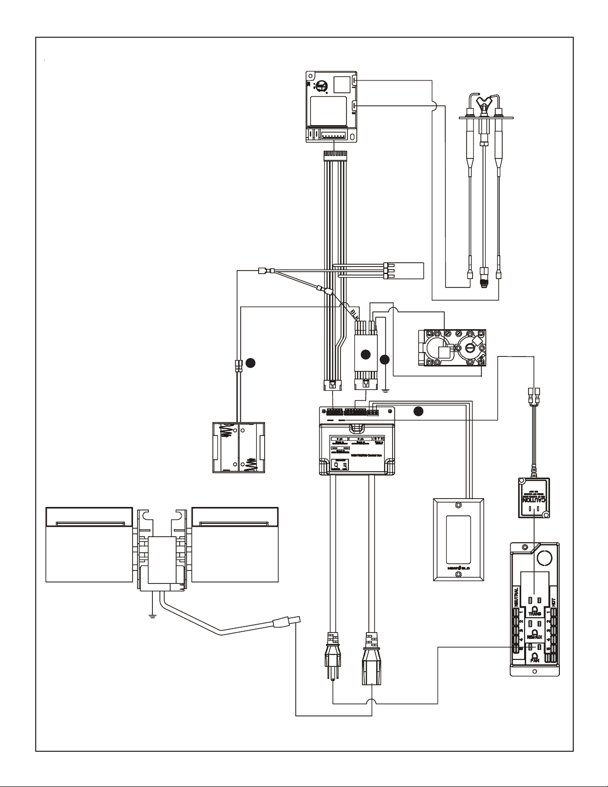
Figure A
MLT-GEMB
- Installation Instructions -
For use with the following controls:
WSK-ML T or other wall thermostats
SCREWS
Disconnecting the Wall Switch Module
1. Remove and discard control panel by removing 2 screws
(see Figure A).
The following step numbers are referenced within
Figures B through E.
2. Unplug 3V adapter from the wall switch module (see
Figure B).
3. Unplug wire harness from ignition module (see Figure B).
4. Unplug the IPI wire assembly from the wall switch module
(see Figure B).
5. Unplug the wall switch module power cable from Junction
box (see Figure B).
6. Unplug fan from the wall switch module (see Figure B).
7. Unplug black battery back-up wire from the wall switch
module (see Figure B).
Disconnecting the IPI wire harness
9. Unplug green wire from valve (see Figure B).
10. Unplug orange wire from valve (see Figure B).
11. Unplug red battery back-up wire from the IPI wire
assembly (see Figure B).
12. With a 1/4" nut driver, disconnect black ground wire
from firebox leg (see Figure B).
13. Discard old IPI wire harness.
14. Disconnect red, green and white wall switch wires and
remove wall switch module.
8. Unplug black wire on IPI harness from the wall switch
module (see Figure B).
Printed in U.S.A. Copyright 2005
Heat & Glo, 20802 Kensington Boulevard, Lakeville, MN 55044
370-931D 12/05
1
IGNITION MODULE 3 VAC
WIRE HARNESS
BLK
Z
INTERMITTENT PILOT IGNITOR
ORG
WHT
BLOWER
RED
BLK
11
^
IPI BAT T E RY PACK
_
[
ORG
a
VALVE
13
12
GROUND TO
FIREPLACE
LEG
`
GRN
Y
14
WALL SWITCH MODULE
TRANSFORMER
3 VAC
WALL SWITCH
GROUND TO
FIREPLACE
CHASSIS
Figure B. IPI Wiring Diagram - Current
]
\
JUNCTION BOX
2

Figure C.
16
WING NUT
CONTROL P ANEL
15
WIRE ASSEMBLY
Reconnecting the fan
NOTE: Some remote and wired controls include fan
operation. Consult instructions included with the
control for proper fan connections. If consulting
separate instructions, ignore this section and go to
Step 20.
15. Locate the control panel wire assembly included with
the ML T-GEMB (see Figure C).
16. Install the temperature sensor switch to the weld stud,
located above the firebox leg. Fasten in place with the
included wing nut.
FAN
SPEED CONTROL
(RHEOSTAT)
17. Plug the blue wire into the Junction box (see Figure D).
18. Plug the black wire from the Rheostat into the Junction
box (see Figure D).
19. Plug the power cord from the fan into the Junction box
(see Figure D).
W ARNING
Shock hazard.
Always disconnect the cord from junction box
before making connections.
• Blower speed control, temperature sensor
switch and blower unit operate on 110 VAC.
JUNCTION BOX
TEMPERATURE
SENSOR SWITCH
Figure D. Fan Wiring Diagram
17
19
18
K
C
A
L
B
E
U
L
B
3

JUNCTION
BOX
IGNITION
MODULE 3 VAC
INTERMITTENT
PILOT IGNITOR
FLAME
ON/OFF
SWITCH
TRANSFORMER
3 VAC
PLUG IN
J-BOX
BLACK
G
R
E
E
N
DELAY CIRCUIT
26
24
BATTERY
BACK-UP
REMOTE THERMOSTAT
WIRES
Figure E. IPI Wiring Digram for ML T-GEMB
27
BLACK
RED
23
GREEN
25
FIREPLACE
GROUND
TO
LEG
BROWN
BROWN
WHT
ORG
22
PILOT
ON/OFF
SWITCH
21
ORG
20
VALVE
GRN
Reconnecting the new IPI wire harness
20. Plug the green wire, labeled “Main”, into the green
terminal on the valve (see Figure E).
21. Plug the orange wire, labeled “Pilot”, into the orange
terminal on the valve (see Figure E).
22. Connect the black wire, labeled “GND”, to the firebox
leg with a screw (see Figure E).
23. Plug the red wire, labeled “+”, into the red wire on the
battery back-up (see Figure E).
24. Locate the spade that is attached to the 2 black wires.
Plug the spade into the black wire on the battery backup (see Figure E).
25. Connect the wire harness to the ignition module (see
Figure E).
26. Connect thermostat wires to the red/brown remote
thermostat wires (labeled).
Starting the unit
27. Plug the 3V adapter into the ignition module (see
Figure E).
28. Attach the new control panel to the unit with 2 screws
(see Figure A).
29. Flip the pilot switch to “ON”.
30. Flip the burner switch to “ON”.
Note: There will be a 3 minute delay before the valve
will send gas to the burner.
4

Thermostat Operation
31. Use of a thermostat requires the pilot switch to be “ON”.
After the inital ignition of the pilot AND subsequent 3
minute delay , the fireplace will turn on and off whenever
the thermostat calls for heat.
Connecting WSK-MLT
32. Follow wiring diagram (Figure F) when connecting the
WSK-MLT.
BLACK
GREEN
GREEN
GROUND
BLACK
GREEN
GREEN
PILOT
ON/OFF
IPI
MODULE
IPI
VALVE
FLAME
SOLENOID
DELAY
ORANGE
GREEN
FLAME
ON/OFF
FLAME HIGH/LOW
Figure F . IPI Wiring Digram for WSK-ML T
FLAME ON
AUX
CONNECTION
1
2
3
4
5
6
7
8
RED
BLACK
RED
BROWN
RED
AC
PLUG
BROWN
BROWN
3V DC
ORANGE
IPI PILOT
BLACK
BLACK
RED
BLACK
BATTERY
RED
BROWN
BROWN
RED
BLACK
ORANGE
GROUND
PIGTAIL
GREEN
BATTERIES
BLACK
RED
YELLOW (HNG) WHITE (HTL)
GREEN
RED
FRONT VIEW
YELLOW
YELLOW
FAN THERMOSTAT
CONNECTION
REAR VIEW
FACTORY
CONNECTED
TOGETHER
FAN
5
 Loading...