

Page 1
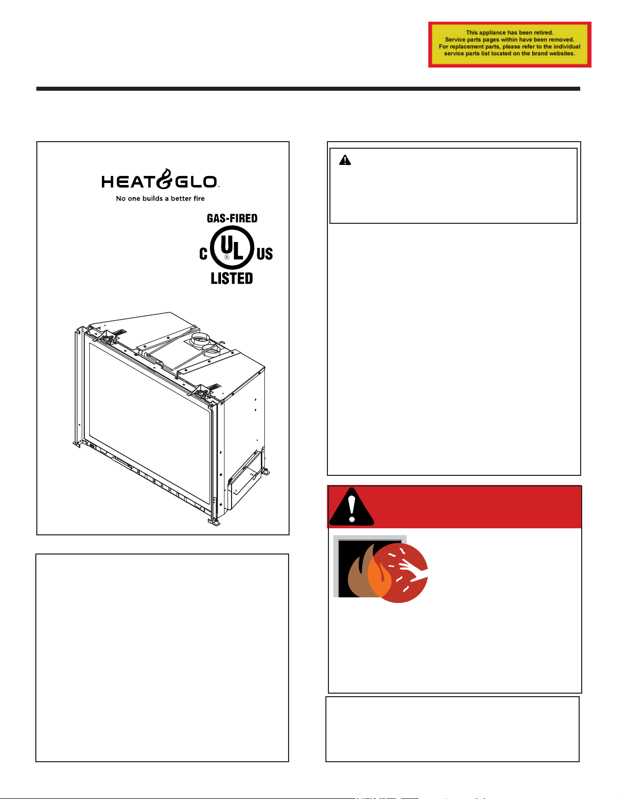
Owner’s Manual
Care and Operation
INSTALLER: Leave this manual with party responsible for use and operation.
OWNER: Retain this manual for future reference.
Contact your dealer with questions regarding installation, operation or service.
NOTICE: DO NOT discard this manual!
Model(s):
ESCAPE-I35-F
ESCAPE-I35LP-F
ESCAPE-I30-F
ESCAPE-I30LP-F
WARNING:
FIRE OR EXPLOSION HAZARD
Failure to follow safety warnings exactly
could result in serious injury, death, or
property damage.
• DO NOT store or use gasoline or other am-
mable vapors and liquids in the vicinity of this
or any other appliance.
• What to do if you smell gas
- DO NOT try to light any appliance.
- DO NOT touch any electrical switch. DO
NOT use any phone in your building.
- Leave the building immediately.
- Immediately call your gas supplier from
a neighbor’s phone. Follow the gas supplier’s instructions.
- If you cannot reach your gas supplier, call
the re department.
• Installation and service must be performed
by a qualied installer, service agency, or the
gas supplier.
This appliance may be installed as an OEM
installation in manufactured home (USA
only) or mobile home and must be installed
in accordance with the manufacturer’s
instructions and the Manufactured Home
Construction and Safety Standard, Title 24
CFR, Part 3280 in the United States, or the
Standard for Installation in Mobile Homes,
CAN/CSA Z240 MH Series, in Canada.
This appliance is only for use with the type(s)
of gas indicated on the rating plate. This
appliance is not convertible for use with other
gases, unless a certied kit is used.
Heat & Glo • Escape-I35-F, Escape-I30-F Owner’s Manual • 2347-981 Rev. M • 3/18
DANGER
HOT GLASS WILL
CAUSE BURNS.
DO NOT TOUCH GLASS
UNTIL COOLED.
NEVER ALLOW CHILDREN
TO TOUCH GLASS.
A barrier designed to reduce the risk of
burns from the hot viewing glass is provided
with this appliance and shall be installed for
the protection of children and other at-risk
individuals.
In the Commonwealth of Massachusetts installation must be
performed by a licensed plumber or gas tter.
See appliance installation manual for additional
Commonwealth of Massachusetts requirements.
1
Page 2
Welcome
1
Read this manual before operating this appliance.
Please retain this Owner’s Manual for future reference.
Read the Installation Manual before making any installation or nishing changes.
A. Congratulations
Congratulations on selecting a Heat & Glo gas replace, an
elegant and clean alternative to wood burning replaces.
The Heat & Glo gas replace you have selected is designed
to provide the utmost in safety, reliability, and efciency.
As the owner of a new replace, you’ll want to read and
carefully follow all of the instructions contained in this
owner’s manual. Pay special attention to all cautions and
warnings.
This owner’s manual should be retained for future
reference. We suggest that you keep it with your other
important documents and product manuals.
The information contained in this owner’s manual, unless
noted otherwise, applies to all models and gas control
systems.
Your new Heat & Glo gas replace will give you years of
durable use and trouble-free enjoyment. Welcome to the
Heat & Glo family of replace products!
Local Dealer Information
DEALER: Fill in
your name, address,
phone and email
information here and
appliance information
below.
Appliance Information:
Brand: ________________________________________________ Model Name: ___________________________
Dealer Name: ________________________________________________________
Address: ____________________________________________________________
____________________________________________________________
Phone: _____________________________________________________________
Email: _____________________________________________________________
Serial Number: __________________________________________ Date Installed: __________________________
Listing Label Information/Location
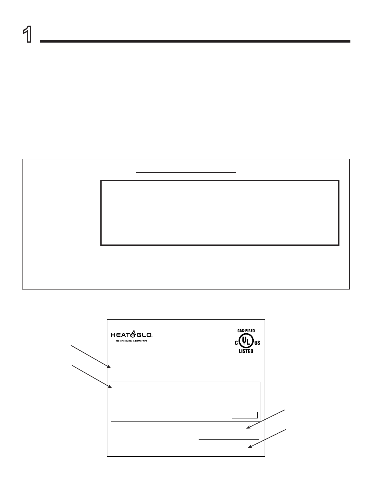
The model information regarding your specic replace can be found on
the rating plate usually located in the control area of the replace.
Model Number
Serial Number
Type of Gas
Gas and Electric
Information
Heat & Glo, a brand of Hearth & Home Technologies
7571 215th Street West, Lakeville, MN 55044
Not Not for for use use with with solid solid fuel.fuel.
((Ne Ne doit doit pas pas entre entre utilise utilise avec avec un un combustible combustible solide).solide).
Type Type of of Gas Gas (Sorte (Sorte De De Gaz)Gaz)::
NNAATURALTURAL GASGAS
Minimum Minimum Permissible Permissible Gas Gas Supply Supply for for Purposes Purposes of of Input Input Adjustment.Adjustment.
Approved Approved Minimum Minimum (De (De Gaz) Gaz) AcceptableAcceptable 0.00.0 in in w.c.w.c. (Po. (Po. Col. Col. d’eau)d’eau)
Maximum Maximum Pressure Pressure (Pression)(Pression) 0.00.0 in in w.c.w.c. (Po. (Po. Col. Col. d’eau)d’eau)
Maximum Maximum Manifold Manifold Pressure Pressure (Pression)(Pression) 0.00.0 in in w.c.w.c. (Po. (Po. Col. Col. d’eau)d’eau)
Minimum Minimum Manifold Manifold Pressure Pressure (Pression)(Pression) 0.00.0 in in w.c.w.c. (Po. (Po. Col. Col. d’eau)d’eau)
Total To tal Electrical Electrical Requirements: Requirements: 000Vac, 000Vac, 00Hz., 00Hz., less less than than 00 00 AmperesAmperes
ALTITUDE:ALTITUDE: 0-0000 0-0000 FT.FT. 0000-0000FT.0000-0000FT.
MAX. MAX. INPUT INPUT BTUH:BTUH: 00,00000,000 00,00000,000
MIN. MIN. INPUT INPUT BTUH:BTUH: 00,00000,000 00,00000,000
ORIFICE ORIFICE SIZE:SIZE: #XXXXX#XXXXX #XXXXX#XXXXX
This This appliance appliance must must be be installed installed in in accordance accordance with with local local codes, codes, if if any; any; if if not, not, follow follow ANSI ANSI Z223.1Z223.1
in in the the USA USA or or CAN/CGA CAN/CGA B149 B149 installation installation codes. codes. (Installer (Installer l’appareil l’appareil selon selon les les codes codes ou ou reglementsreglements
locaux locaux ou, ou, en en l’absence l’absence de de tels tels reglements, reglements, selon selon les les codes codes d’installation d’installation CAN/CGA-B149.)CAN/CGA-B149.)
ANSI ANSI Z21XX-XXXX Z21XX-XXXX · · CSA CSA 2.XX-MXX 2.XX-MXX · · UL307BUL307B
IN IN CANADACANADA
Model:Model:
(Modele):(Modele):
SerialSerial
(Serie):(Serie):
MADE MADE IN IN USAUSA
XXXXXXXXXXXXXXXX
XXXXXXXXXXXXXXXX
2
Heat & Glo • Escape-I35-F, Escape-I30-F Owner’s Manual • 2347-981 Rev. M • 3/18
Page 3

Safety Alert Key:
• DANGER! Indicates a hazardous situation which, if not avoided will result in death or serious injury.
• WARNING! Indicates a hazardous situation which, if not avoided could result in death or serious injury.
• CAUTION! Indicates a hazardous situation which, if not avoided, could result in minor or moderate injury.
• NOTICE: Used to address practices not related to personal injury.
Table of Contents
1 Welcome
A. Congratulations ................................. 2
B. Limited Lifetime Warranty .......................... 4
2 Product Specic Information
A. Appliance Certication ............................6
B. Glass Specications ..............................6
C. BTU Specications ............................... 6
D. High Altitude Installations .......................... 6
3 Important Safety and Operating Information
A. Appliance Safety ................................ 7
B. General Operating Parts .......................... 8
C. Fuel Specications ............................... 8
D. Wall Surface/TV Guidelines ........................8
E. Before Lighting Appliance. . . . . . . . . . . . . . . . . . . . . . . . . . 8
F. Lighting Instructions (IPI) ..........................9
G. Appliance Break-In .............................. 10
H. Heat Management ..............................10
I. Operation During A Power Outage (IPI Plus) .........10
J. Detailed Component Operating Instructions
- IntelliFire
TM
Plus .............................. 11
4 Maintenance and Service
A. Maintenance: Frequency and Tasks ................ 13
B. Maintenance Tasks - Homeowner ..................13
C. Maintenance Tasks - Qualied Service Technician ..... 15
5 Frequently Asked Questions and Troubleshooting
A. Frequently Asked Questions ......................17
B. Troubleshooting ................................18
6 Reference Materials
A. Accessories ...................................20
B. Service Parts .................................. 21
C. Contact Information ............................. 25
= Contains updated information.
Heat & Glo • Escape-I35-F, Escape-I30-F Owner’s Manual • 2347-981 Rev. M • 3/18
3
Page 4
B. Limited Lifetime Warranty
Wood
All parts and material except as
listed
Igniters, electronic components,
and glass
X X X X X Factory-installed blowers
X Firepots and burnpots
5 years 1 year X X Castings and baffles
Manifold tubes,
HHT chimney and termination
years
Lifetime
beyond warranty period
3 years
Hearth & Home Technologies
LIMITED LIFETIME WARRANTY
Hearth & Home Technologies, on behalf of its hearth brands (“HHT”), extends the following warranty for HHT
gas, wood, pellet, coal and electric hearth appliances that are purchased from an HHT authorized dealer.
WARRANTY COVERAGE:
HHT warrants to the original owner of the HHT appliance at the site of installation, and to any transferee taking ownership
of the appliance at the site of installation within two years following the date of original purchase, that the HHT appliance
will be free from defects in materials and workmanship at the time of manufacture. After installation, if covered components manufactured by HHT are found to be defective in materials or workmanship during the applicable warranty period,
HHT will, at its option, repair or replace the covered components. HHT, at its own discretion, may fully discharge all of its
obligations under such warranties by replacing the product itself or refunding the verified purchase price of the product
itself. The maximum amount recoverable under this warranty is limited to the purchase price of the product. This warranty
is subject to conditions, exclusions and limitations as described below.
WARRANTY PERIOD:
Warranty coverage begins on the date of original purchase. In the case of new home construction, warranty coverage
begins on the date of first occupancy of the dwelling or six months after the sale of the product by an independent,
authorized HHT dealer/ distributor, whichever occurs earlier. The warranty shall commence no later than 24 months
following the date of product shipment from HHT, regardless of the installation or occupancy date. The warranty period for
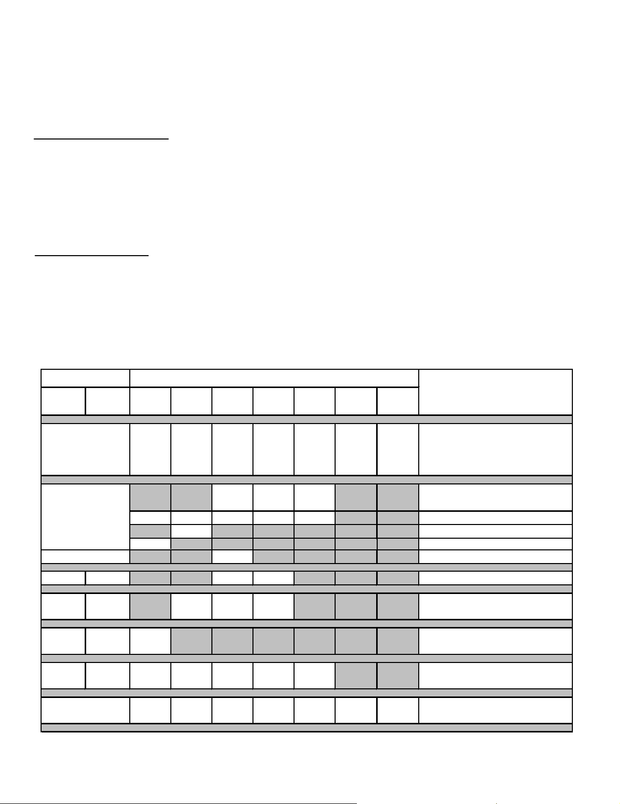
parts and labor for covered components is produced in the following table.
The term “Limited Lifetime” in the table below is defined as: 20 years from the beginning date of warranty coverage for
gas appliances, and 10 years from the beginning date of warranty coverage for wood, pellet, and coal appliances. These
time periods reflect the minimum expected useful lives of the designated components under normal operating conditions.
Warranty Period HHT Manufactured Appliances and Venting
Parts Labor Gas Wood Pellet
1 Year
XXXXXXX
EPA
Coal Electric Venting
XXX
2 years
X Molded refractory panels
X
7 years 3 years X X X
10
Limited
1 year X Burners, logs and refractory
3 years X X X X X Firebox and heat exchanger
Components Covered
covered by Conditions,
Exclusions, and Limitations
Ignition Modules
90 Days
4021-645H 10/15 Page 1 of 2
4
XXXXXXX
See conditions, exclusions, and limitations on next page.
Heat & Glo • Escape-I35-F, Escape-I30-F Owner’s Manual • 2347-981 Rev. M • 3/18
All replacement parts
Page 5

B. Limited Lifetime Warranty (continued)
WARRANTY CONDITIONS:
• This warranty only covers HHT appliances that are purchased through an HHT authorized dealer or distributor. A list of
HHT authorized dealers is available on the HHT branded websites.
• This warranty is only valid while the HHT appliance remains at the site of original installation.
• This warranty is only valid in the country in which the HHT authorized dealer or distributor that sold the appliance
resides.
• Contact your installing dealer for warranty service. If the installing dealer is unable to provide necessary parts, contact
the nearest HHT authorized dealer or supplier. Additional service fees may apply if you are seeking warranty service
from a dealer other than the dealer from whom you originally purchased the product.
• Check with your dealer in advance for any costs to you when arranging a warranty call. Travel and shipping charges
for parts are not covered by this warranty.
WARRANTY EXCLUSIONS:
This warranty does not cover the following:
• Changes in surface finishes as a result of normal use. As a heating appliance, some changes in color of interior and
exterior surface finishes may occur. This is not a flaw and is not covered under warranty.
• Damage to printed, plated, or enameled surfaces caused by fingerprints, accidents, misuse, scratches, melted items,
or other external sources and residues left on the plated surfaces from the use of abrasive cleaners or polishes.
• Repair or replacement of parts that are subject to normal wear and tear during the warranty period. These parts
include: paint, wood, pellet and coal gaskets, firebricks, grates, flame guides, batteries and the discoloration of glass.
• Expansion, contraction, or movement of certain parts causing noise. These conditions are normal and complaints
related to this noise are not covered by this warranty.
• Damages resulting from: (1) failure to install, operate, or maintain the appliance in accordance with the installation
instructions, operating instructions, and listing agent identification label furnished with the appliance; (2) failure to
install the appliance in accordance with local building codes; (3) shipping or improper handling; (4) improper operation, abuse, misuse, continued operation with damaged, corroded or failed components, accident, or improperly/
incorrectly performed repairs; (5) environmental conditions, inadequate ventilation, negative pressure, or drafting
caused by tightly sealed constructions, insufficient make-up air supply, or handling devices such as exhaust fans or
forced air furnaces or other such causes; (6) use of fuels other than those specified in the operating instructions; (7)
installation or use of components not supplied with the appliance or any other components not expressly authorized
and approved by HHT; (8) modification of the appliance not expressly authorized and approved by HHT in writing;
and/or (9) interruptions or fluctuations of electrical power supply to the appliance.
• Non-HHT venting components, hearth components or other accessories used in conjunction with the appliance.
• Any part of a pre-existing fireplace system in which an insert or a decorative gas appliance is installed.
• HHT’s obligation under this warranty does not extend to the appliance’s capability to heat the desired space. Information is provided to assist the consumer and the dealer in selecting the proper appliance for the application. Consideration must be given to appliance location and configuration, environmental conditions, insulation and air tightness of
the structure.
This warranty is void if:
• The appliance has been over-fired or operated in atmospheres contaminated by chlorine, fluorine, or other damaging
chemicals. Over-firing can be identified by, but not limited to, warped plates or tubes, rust colored cast iron, bubbling,
cracking and discoloration of steel or enamel finishes.
• The appliance is subjected to prolonged periods of dampness or condensation.
• There is any damage to the appliance or other components due to water or weather damage which is the result of, but
not limited to, improper chimney or venting installation.
LIMITATIONS OF LIABILITY:
• The owner’s exclusive remedy and HHT’s sole obligation under this warranty, under any other warranty, express or
implied, or in contract, tort or otherwise, shall be limited to replacement, repair, or refund, as specified above. In no
event will HHT be liable for any incidental or consequential damages caused by defects in the appliance. Some states
do not allow exclusions or limitation of incidental or consequential damages, so these limitations may not apply to you.
This warranty gives you specific rights; you may also have other rights, which vary from state to state. EXCEPT TO
THE EXTENT PROVIDED BY LAW, HHT MAKES NO EXPRESS WARRANTIES OTHER THAN THE WARRANTY
SPECIFIED HEREIN. THE DURATION OF ANY IMPLIED WARRANTY IS LIMITED TO DURATION OF THE
EXPRESSED WARRANTY SPECIFIED ABOVE.
4021-645H 10/15 Page 2 of 2
Heat & Glo • Escape-I35-F, Escape-I30-F Owner’s Manual • 2347-981 Rev. M • 3/18
5
Page 6
Product Specic Information
2
A. Appliance Certication
MODELS: ESCAPE-I30-F, ESCAPE-I30LP-F,
ESCAPE-I35-F, ESCAPE-I35LP-F
LABORATORY: Underwriters Laboratories, Inc. (UL)
TYPE: Direct Vent Heater
STANDARD: ANSI Z21.88-2014 • CSA 2.33-2014
This product is listed to ANSI standards for “Vented Gas
Fireplace Heaters” and applicable sections of “Gas Burning Heating Appliances for Manufactured Homes and
Recreational Vehicles”, and “Gas Fired Appliances for
Use at High Altitudes”.
Heat & Glo gas inserts are designed for installations into
solid fuel masonry or factory built replaces that have been
installed in accordance with the National, Provincial, State
and local building codes. Fireplaces are to be constructed
of non-combustible materials and, in the absence of local
or regional codes, meet criteria of NFPA 211. No additional
outside air source is required.
NOTICE: This installation must conform with local codes.
In the absence of local codes you must comply with the
National Fuel Gas Code, ANSI Z223.1-latest edition in
the U.S.A. and the CAN/CGA B149 Installation Codes in
Canada.
NOT INTENDED FOR USE AS A PRIMARY HEAT SOURCE.
This appliance is tested and approved as either supplemental room heat or as a decorative appliance. It should not be
factored as primary heat in residential heating calculations.
Installation and service of this appliance should be performed by
qualied personnel. Hearth & Home Technologies recommends
HHT Factory Trained or NFI certied professionals.
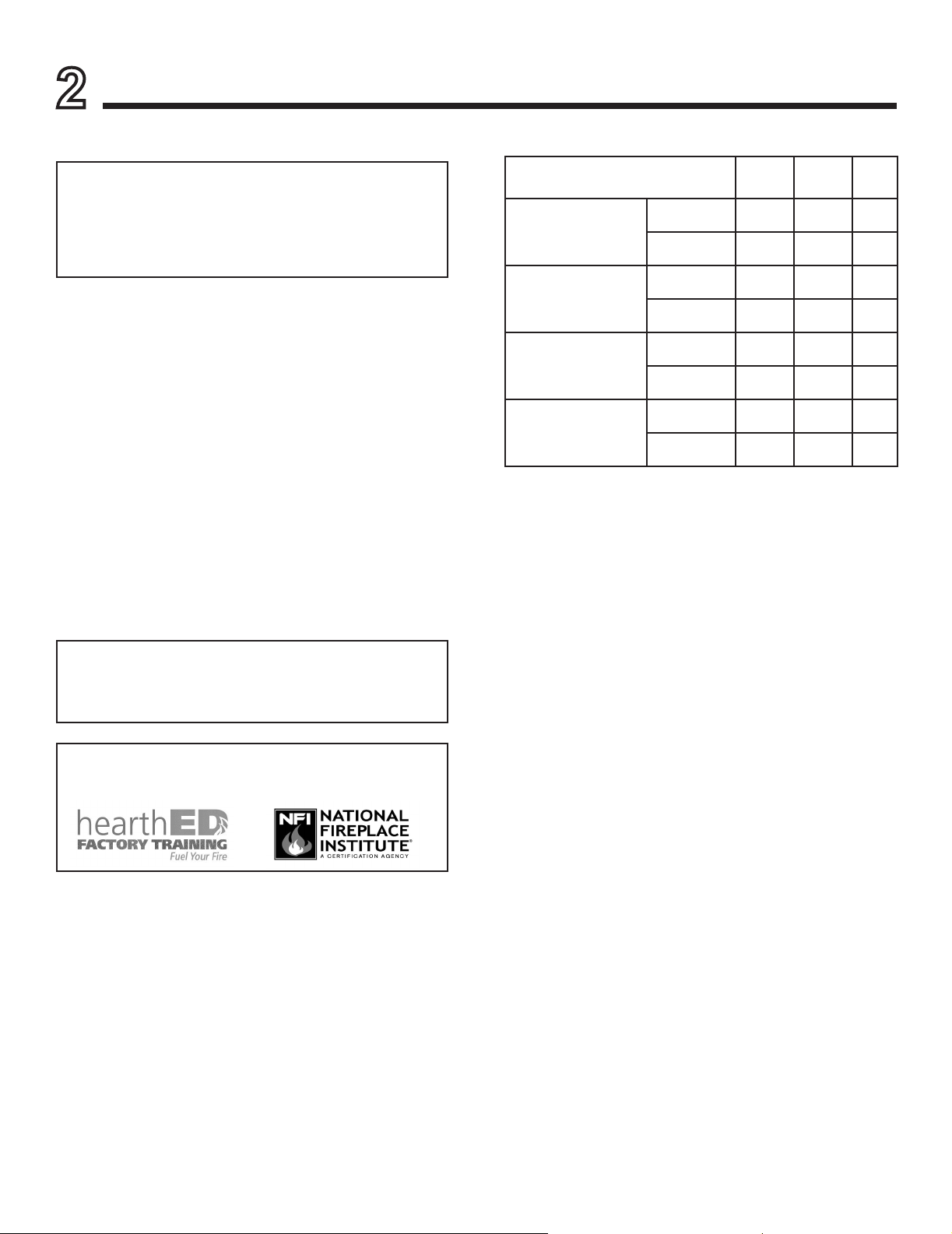
C. BTU Specications
Models
(U.S. or Canada)
ESCAPE-I30-F
(NG)
ESCAPE-I30LP-F
(LP)
Escape-I35-F
(NG)
ESCAPE-I35LP-F
(LP)
US
(0-2000 FT)
CANADA
(2000-4500 FT)
US
(0-2000 FT)
CANADA
(2000-4500 FT)
US
(0-2000 FT)
CANADA
(2000-4500 FT)
US
(0-2000 FT)
CANADA
(2000-4500 FT)
Maximum
Input
BTU/h
36,000 17,000 33
33,250 16,750 34
36,000 19,000 50
31,000 15,500 51
40,000 20,000 31
37,000 19,250 32
38,000 19,000 49
35,000 17,000 50
Minimum
Input
BTU/h
Orice
Size
(DMS)
D. High Altitude Installations
NOTICE: If the heating value of the gas has been reduced,
these rules do not apply. Check with your local gas utility
or authorities having jurisdiction.
When installing above 2000 feet elevation:
• In the USA: Reduce input rate 4% for each 1000 feet
above 2000 feet.
• In CANADA: Reduce input rate 10% for elevations
between 2000 feet and 4500 feet. Above 4500 feet,
consult local gas utility.
Check with your local gas utility to determine proper
orice size.
B. Glass Specications
This appliance is equipped with 5 mm ceramic glass. Replace glass only with 5 mm ceramic glass. Please contact
your dealer for replacement glass.
6
Heat & Glo • Escape-I35-F, Escape-I30-F Owner’s Manual • 2347-981 Rev. M • 3/18
Page 7
3
Important Safety and Operating Information
A. Appliance Safety
WARNING! DO NOT operate replace before reading
and understanding operating instructions. Failure
to operate replace according to operating instructions
could cause re or injury.
DANGER
HOT GLASS WILL
CAUSE BURNS.
DO NOT TOUCH GLASS
UNTIL COOLED.
NEVER ALLOW CHILDREN
TO TOUCH GLASS.
• Keep children away.
• CAREFULLY SUPERVISE children in same room
as replace.
• Alert children and adults to hazards of high
temperatures.
High temperatures may ignite clothing or other
ammable materials.
• Clothing, furniture, draperies, and other ammable
materials must not be placed on or near the
appliance.
• Teach children to NEVER touch the replace.
• Consider not using the replace when children will be
present.
Contact your dealer for more information, or visit: www.
hpba.org/Product-Info/Fireplace-Stove-Heater/GlassFronts-Safety.
To prevent unintended operation when not using your replace for an extended period of time (summer months,
vacations, trips, etc):
• Remove batteries from remote controls.
• Turn off wall controls.
• Unplug 6 volt adapter plug (IPI) and remove batteries on
IPI models.
Clear Space
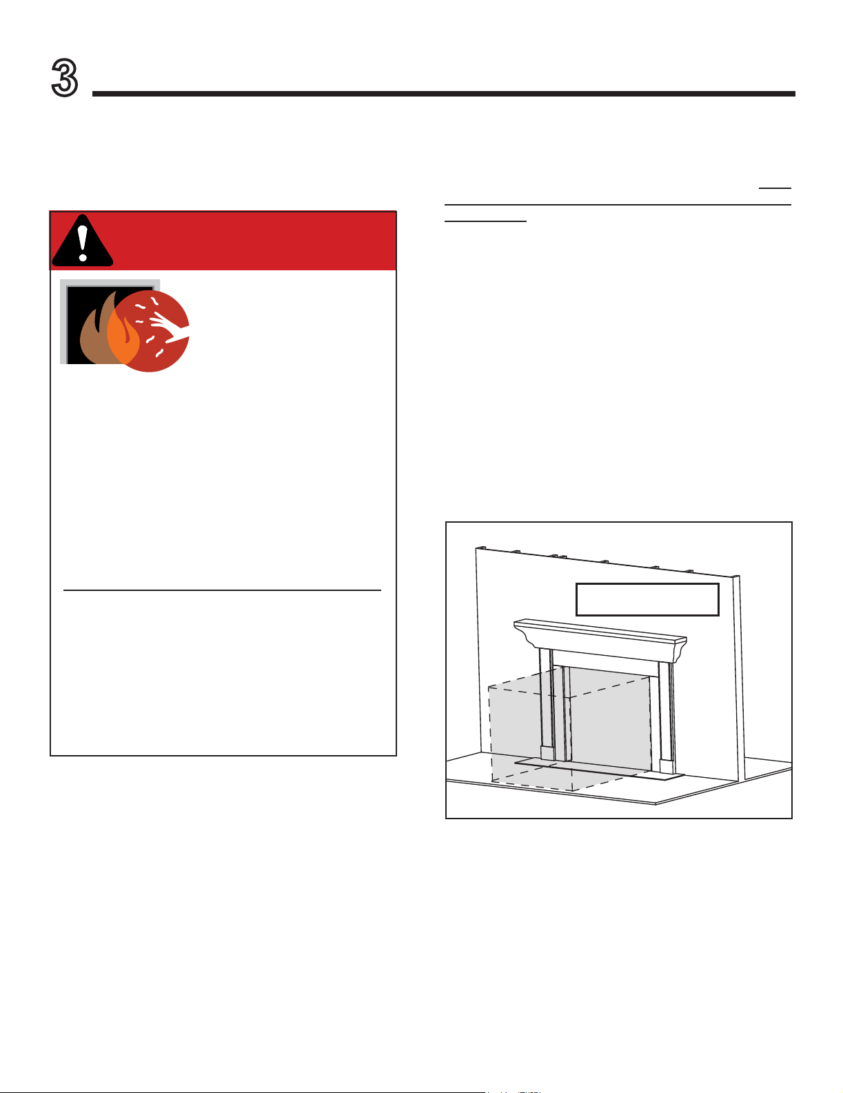
WARNING! DO NOT place combustible objects in front
of the replace or block louvers. High temperatures may
start a re. See Figure 3.1.
Avoid placing candles and other heat-sensitive objects on
mantel or hearth. Heat may damage these objects.
A barrier designed to reduce the risk of burns from the
hot viewing glass is provided with this appliance and
shall be installed for the protection of children and other
at-risk individuals. DO NOT operate the appliance with
the barrier removed. If the barrier becomes damaged,
the barrier shall be replaced with the manufacturer’s
barrier for this appliance.
Contact your dealer or Hearth & Home Technologies if the
barrier is not present or help is needed to properly install one.
Young children should be carefully supervised when they
are in the same room as the appliance. Toddlers, young
children and others may be susceptible to accidental
contact burns.
• A physical barrier is recommended if there are at risk
individuals in the house.
• To restrict access to a replace or stove, install an
adjustable safety gate to keep toddlers, young children
and other at risk individuals out of the room and away
from hot surfaces.
• Install a switch lock or a wall/remote control with child
protection lockout feature.
• Keep remote controls out of reach of children.
• Never leave children alone near a hot replace, whether
operating or cooling down.
APPLIANCE INSTALLED IN EXISTING
SOLID FUEL FIREPLACE
CLEAR SPACE
3 FT. IN
FRONT OF
FIREPLACE
Figure 3.1 Clear Space Requirement - All Models
Heat & Glo • Escape-I35-F, Escape-I30-F Owner’s Manual • 2347-981 Rev. M • 3/18
7
Page 8

B. General Operating Parts
Figure 3.2 references the general operating parts of the
appliance and the section of this manual in which they are
discussed.
DECORATIVE DOORS
(NOT SHOWN)
SECTION 2.E.
FIXED GLASS ASSEMBLY
CLEAR SPACE
SECTION 2.D.
HEARTH
BATTERY BACKUP
ACCESS
SECTION 2.H.
SECTION 12.I.
APPLIANCE INSTALLED IN EXISTING
SOLID FUEL FIREPLACE
MANTEL
SECTION 5.B.
Figure 3.2 General Operating Parts
C. Fuel Specications
WARNING! Risk of Fire or Explosion! Appliance must
be set up for compatible gas type!
• This appliance is designed to operate on either natural
gas or propane. Make sure the appliance is compatible
with gas type selected for installation site.
• Conversions must be made by a qualified service
technician using Hearth & Home Technologies specied
and approved parts.
D. Wall Surface/TV Guidelines
NOTICE: When installing a TV above this appliance,
ensure wall temperature will not exceed temperatures for
operation of TV designated by TV manufacturer.
E. Before Lighting Appliance
Before operating this replace for the rst time, have a
qualied service technician:
• Verify all shipping materials have been removed from
inside and/or underneath the rebox.
• Review proper placement of logs, ember material and/or
other decorative materials.
• Check the wiring.
• Check the air shutter adjustment.
• Ensure that there are no gas leaks.
• Ensure that the glass is sealed and in the proper position
and that the integral barrier is in place.
WARNING! Risk of Fire or Asphyxiation! DO NOT op-
erate replace with xed glass assembly removed.
This replace has an IntellireTM Plus ignition system.
8
Heat & Glo • Escape-I35-F, Escape-I30-F Owner’s Manual • 2347-981 Rev. M • 3/18
Page 9

F. Lighting Instructions (IPI)
FOR YOUR SAFETY READ BEFORE LIGHTING
WARNING: If you do not follow these instructions exactly, a fi re or explosion may result causing property damage, personal injury or loss of life.
A. This appliance is equipped with an intermittent pilot ignition (IPI) device which
automatically lights the burner. DO NOT try to light the burner by hand.
B. BEFORE LIGHTING, smell all around the appliance area for gas. Be sure to smell
next to the fl oor because some gas is heavier than air and will settle on the fl oor.
WHAT TO DO IF YOU SMELL GAS
• DO NOT try to light any appliance.
• DO NOT touch any electric switch; do not use any phone in your building.
• Immediately call your gas supplier from a neighbor’s phone. Follow the gas supplier’s instructions.
• If you cannot reach your gas supplier, call the fi re department.
C. Use only your hand to push in or turn the gas control knob. Never use tools. If
the knob will not push in or turn by hand, DO NOT try to repair it, call a qualifi ed
service technician. Force or attempted repair may result in a fi re or explosion.
D. DO NOT use this appliance if any part has been under water. Immediately call
a qualifi ed service technician to inspect the appliance and to replace any part of
the control system and any gas control which has been under water.
LIGHTING INSTRUCTIONS (IPI)
1. This appliance is equipped with an ignition device which
automatically lights the burner. DO NOT try to light the burner by hand.
GAS
VALVE
2. Wait fi ve (5) minutes to clear out any gas. Then smell for gas, including near the
fl oor. If you smell gas, STOP! Follow “B” in the Safety Information located on the
top of this label. If you do not smell gas, go to next step.
3. To light the burner:
Equipped with wall switch: Turn ON/OFF switch to ON.
Equipped with remote or wall control: Press ON or FLAME button.
Equipped with thermostat: Set temperature to desired setting.
4. If the appliance does not light after three tries, call your service technician or gas
supplier.
TO TURN OFF GAS TO APPLIANCE
1. Equipped with wall switch: Turn ON/OFF switch to OFF.
Equipped with remote or wall control: Press OFF button.
Equipped with thermostat: Set temperature to lowest setting.
2. Service technician should turn off electric power to the control when performing
service.
DANGER
HOT GLASS WILL CAUSE BURNS.
DO NOT TOUCH GLASS UNTIL COOLED.
NEVER ALLOW CHILDREN TO TOUCH GLASS.
A barrier designed to reduce the risk of burns from the hot viewing glass is provided with this
appliance and shall be installed for the protection of children and other at-risk individuals.
WARNING:
DO NOT CONNECT LINE VOLTAGE (110/120 VAC OR 220/240 VAC) TO THE CONTROL VALVE.
Improper installation, adjustment, alteration, service or maintenance can cause
injury or property damage. Refer to the owner’s information manual provided with
this appliance. For assistance or additional information, consult a qualifi ed installer,
service agency or the gas supplier.
This appliance needs fresh air for safe operation and must be installed so there are
provisions for adequate combustion and ventilation air.
If not installed, operated, and maintained in accordance with the manufacturer’s instructions, this product could expose you to substances in fuel or fuel combustion which
are known to the State of California to cause cancer, birth defects, or other reproductive
harm.
Keep burner and control compartment clean. See installation and operating instructions accompanying appliance.
Hearth & Home Technologies replace, please refer to www. replaces.com.
For additional information on operating your
CAUTION:
Hot while in operation. DO NOT touch. Keep children, clothing, furniture, gasoline
and other liquids having fl ammable vapors away.
DO NOT operate the appliance with fi xed glass assembly removed, cracked or
broken. Replacement of the fi xed glass assembly should be done by a licensed or
qualifi ed service person.
NOT FOR USE WITH SOLID FUEL
For use with natural gas and propane. A conversion kit, as supplied by the manufacturer, shall be used to convert this appliance to the alternate fuel.
Also Certifi ed for Installation in a Bedroom or a Bedsitting Room.
This appliance must be installed in accordance with local codes, if any; if none,
follow the National Fuel Gas Code, ANSIZ223.1/ NFPA 54, or the National Gas and
Propane Installation code, CSA B149.1.
593-913i
Heat & Glo • Escape-I35-F, Escape-I30-F Owner’s Manual • 2347-981 Rev. M • 3/18
9
Page 10

G. Appliance Break-In
Initial Break-in Procedure
• The replace should be run three to four hours continuously
on high.
• Turn the replace off and allow it to completely cool.
• Remove xed glass assembly. See Section 4.B.
• Clean xed glass assembly. See Section 4.
• Replace the xed glass assembly and run continuously
on high an additional 12 hours.
This cures the materials used to manufacture the replace.
NOTICE! Open windows for air circulation during replace break-in.
• Some people may be sensitive to smoke and odors.
• Smoke detectors may activate.
Figure 3.3 Battery Tray Located at Bottom Left Side of Appliance
NOTCH
H. Heat Management
Heat Output
Heat Output is managed through the RC300 remote con-
trol that comes standard with the replace.
• Turn the appliance on and off.
• Adjust the height of the ame by varying the input using
the remote control.
• Adjust the fan speed.
For more information, see the instructions that accompany
the remote control.
I. Operation During A Power Outage (IPI Plus)
The IntelliFireTM Plus intermittent pilot ignition system
comes with a battery backup system that enables the
system to operate in a power outage. The system offers
seamless transition from household AC power to battery
backup. Battery longevity and performance will be affected
by long term exposure to the service temperatures of this
appliance.
NOTICE: Batteries should only be used as a power source
in the event of an emergency power outage. Batteries should
not be used as a primary long-term power source.
To Operate Fireplace Using Battery Power (DC):
1. Remove the decorative front or door.
2. IPI Battery Tray/Battery Installation:
The removable battery tray is located in the lower left
corner of the appliance next to the lower glass clip. See
Figure 3.3. A notch on the right side of the tray engages
the tray with the appliance. See Figure 3.4. To remove
the tray, rotate the left side of the tray outward and pull to
the left to disengage the notch. Place four AA cell batteries in the tray and return it to the closed position with the
notch engaged in the appliance. Battery polarity must
be correct or module damage will occur.
10
Heat & Glo • Escape-I35-F, Escape-I30-F Owner’s Manual • 2347-981 Rev. M • 3/18
Figure 3.4 Pull Left Side of Tray Out and Disengage Notch
Figure 3.5 Battery Tray Pulled Out
3. Turn the appliance on according to the instructions
below for the appropriate type of control:
Standard Wireless Remote:
• Remote receiver is integrated into the ignition module
• Use the remote to turn the appliance on.
• To preserve battery life, do not use the HI/LO ame
or THERMOSTAT options.
Wall Switch or Factory-Installed ON/OFF Switch:
• Toggle the switch as you would under normal
circumstances.
Ignition Module:
• Locate the ignition module in the control cavity.
• Slide the ON/REMOTE/OFF switch to the ON
position.
NOTICE: Some functionality will be lost when using
battery backup including remote control, fan, lights, or
any other auxiliary functions that require household 110-
120 VAC power.
Page 11

To Return to Operation Using Electrical (AC) Power
Wall Switch or Factory-Installed ON/OFF Switch:
• Toggle the switch to OFF and remove the batteries
from the battery tray. Replace door or decorative front
on appliance.
Wireless Remote:
• No adjustment to the module is required if using the
standard remote control. The module remains in the
REMOTE setting.
Ignition Module:
• Slide the ON/REMOTE/OFF switch to the REMOTE
position.
Remove the batteries from the battery tray. Replace
door or decorative front on appliance.
J. Detailed Component Operating Instruc-
tions - IntelliFire
TM
Plus
Control Module Operation
1. The control module has an ON/OFF/REMOTE selector
switch that must be set. See Figure 3.6.
OFF Position: Appliance will ignore all power inputs and
will not respond to any commands from a wall switch
or remote. The unit should be in the OFF position
during installation, service, battery installation, fuel
conversion, and in the event that the control goes into
LOCK-OUT mode as a result of an error code.
ON Position: Appliance will ignite and run continuously
in the HI ame setting, with no adjustment in ame
output. This mode of operation is primarily used for
initial installation or power outage operation with battery
backup.
REMOTE Position: Appliance will initiate commands
from an optional wired wall switch and/or the wireless
remote (RC300).
2. If using a wired wall switch with the module in REMOTE
mode, the ame output can be adjusted with the HI/
LO selector switch on the module. See Figure 3.6.
Note that the ame HI/LO selector switch will become
inactive once an optional remote control (RC200/
RC300) is programmed to the control module. Note that
the control module will always ignite the replace on HI
and remain so for the initial 10 seconds of operation.
If the HI/LO is switched to the LO position, the ame
output will automatically drop to the lowest setting after
the ame has been established for 10 sec. After this
10 second period, the ame can be adjusted from HI
to LO with the switch.
3. The control module has safety feature that automatically
shuts down the replace after 9 hours of continuous
operation without receiving a command from the RC300
remote.
4. If you intend to use both an optional wired wall switch
and the RC300 remote control to operate your replace,
the wall switch will override any commands given by
the remote.
MODULE
FLAME HI/LOW
SWITCH
Figure 3.6 Control Module
Heat & Glo • Escape-I35-F, Escape-I30-F Owner’s Manual • 2347-981 Rev. M • 3/18
STATUS
INDICATOR LED
SELECTOR
SWITCH
NG/LP GAS-TYPE
SELECTOR SWITCH
11
Page 12

5. Module Reset
MODULE RESET SWITCH
This module may lock-out under certain conditions.
When this occurs, the appliance will not ignite or
respond to commands. The module will go into lock-out
mode by emitting three audible beeps, then continuously
displaying a RED/GREEN error code at its status
indicator LED.
• Check battery tray. Remove batteries if installed.
Batteries should only be installed for use during power
outages. See Section G.
• Locate the module reset switch. (See Figure 3.7).
• Set the module reset switch to the OFF position.
• Wait ve (5) minutes to allow possible accumulated gas
to clear.
• Set the module reset switch to ON or REMOTE position.
• Start the appliance.
WARNING! Risk of Explosion! DO NOT press the mod-
ule reset switch more than one time within a ve minute
time period. Gas may accumulate in rebox. Call a qualied service technician.
Appliance ON/OFF:
The appliance may be turned on and off by the RC300 re-
mote control that comes standard with the replace. Consult the instructions and quick reference guide included
with the RC300 for more information.
Fan ON/OFF:
The fan may be turned on and off and the speed adjusted
by the RC300 remote control that comes standard with
the replace. Consult the instructions and quick reference guide included with the RC300 for more information.
Nine Hour Safety Shutdown Feature
The appliance has a safety feature that automatically
shuts down the replace after nine hours of continuous
operation without receiving a command from the wall
switch or optional remote.
Figure 3.7. Module Reset Switch
12
Heat & Glo • Escape-I35-F, Escape-I30-F Owner’s Manual • 2347-981 Rev. M • 3/18
Page 13

4
Maintenance and Service
Any safety screen or guard removed for servicing must be
replaced prior to operating the replace.
When properly maintained, your replace will give you
many years of trouble-free service. Contact your dealer
to answer questions regarding proper operation, troubleshooting and service for your appliance. Visit www.
heatnglo.com to locate a dealer. We recommend annual
service by a qualied service technician.
A. Maintenance: Frequency and Tasks
Task Frequency To be completed by
Glass Cleaning Seasonally
Doors/Fronts/
Surrounds
Remote Control Seasonally
Venting Seasonally
Gasket Seal
and Glass
Inspection
Log Inspection Annually
Firebox
Inspection
Control
Compartment &
rebox Top
Burner Ignition
& Operation
Light Bulbs As needed
Firebox
(FireBrick)
Annually
Annually
Annually
Annually
Annually
Annually
Homeowner
Qualied Service
Technician
Glass Cleaning
Frequency: Seasonally
By: Homeowner
Tools Needed: Protective gloves, glass cleaner, drop
cloth and a stable work surface.
CAUTION! Handle xed glass assembly with care.
Glass is breakable.
• Avoid striking, scratching or slamming glass
• Avoid abrasive cleaners
• DO NOT clean glass while it is hot
• Prepare a work area large enough to accommodate xed
glass assembly and door frame by placing a drop cloth
on a at, stable surface.
Note: Fixed glass assembly and gasketing may have residue that can stain carpeting or oor surfaces.
• Remove door or decorative front from replace and set
aside on work surface.
Removing Fixed Glass Assembly
• The glass assembly fastens to the replace in four
places. The fastening mechanisms are spring-loaded
glass latches. An example of the top glass latch is shown
in Figure 4.1 and an example of the bottom glass latch
is shown in Figure 4.2.
B. Maintenance Tasks - Homeowner
Installation and repair should be done by a qualied service
technician only. The appliance should be inspected before
use and at least annually by a professional service person.
The following tasks may be performed annually by the
homeowner. If you are uncomfortable performing any of
the listed tasks, please call your dealer for a service appointment.
More frequent cleaning may be required due to excessive
lint from carpeting, bedding material, et cetera. It is imperative that control compartments, burners and circulat-
ing air passageways of the appliance be kept clean. Any
safety screen, guard, or barrier removed for servicing the
appliance must be replaced prior to operating the appliance.
CAUTION! Risk of Burns! The replace should be
turned off and cooled before servicing.
Heat & Glo • Escape-I35-F, Escape-I30-F Owner’s Manual • 2347-981 Rev. M • 3/18
GLASS LATCH
Figure 4.1 Top Glass Latch
GLASS LATCH
PULL OUT
Figure 4.2 Bottom Glass Latch
13
Page 14

• To remove glass assembly, release one top glass latch at
a time. Use one hand to support the glass while pulling
the top spring-loaded latch forward with the other hand.
See Figure 4.3.
Figure 4.3 Release Glass Latches One at a Time
• Once both top latches are disengaged, grab the glass
frame assembly by the sides and tilt it outward and
downward. Lift up slightly to disengage the glass
assembly from the bottom glass latches. See Figure 4.4.
Replacing Fixed Glass Assembly
• Tilt glass assembly toward replace and slide glass
assembly downward to engage bottom latches. Verify
bottom latches are fully engaged and then fasten the
two top latches.
• Note that the extended glass latch tabs on the glass
frame are for the bottom glass latches.
Doors, Surrounds, Fronts
Frequency: Annually
By: Homeowner
Tools needed: Protective gloves, stable work surface
• Assess condition of screen and replace as necessary.
• Inspect for scratches, dents or other damage and repair
as necessary.
• Check that louvers are not blocked.
• Vacuum and dust surfaces.
Remote Control
Frequency: Seasonally
By: Homeowner
Tools needed: Replacement batteries and remote con-
trol instructions.
• Locate remote control transmitter and receiver.
• Verify operation of remote. Refer to remote control
operation instructions for proper calibration and setup
procedure.
• Place batteries as needed in remote transmitters and
battery-powered receivers.
• Place remote control out of reach of children.
If not using your replace for an extended period of time
(summer months, vacations/trips, etc), to prevent unintended operation:
• Remove batteries from remote controls.
• Unplug 3 volt adapter plug on IPI models.
Figure 4.4 Tilt Glass Down and Lift Up to Disengage Bottom Latch
• Clean glass with a non-abrasive commercially available
cleaner.
- Light deposits: Use a soft cloth with soap and water
- Heavy deposits: Use commercial fireplace glass
cleaner (consult with your dealer)
• Carefully set xed glass assembly in place on replace.
Hold glass in place with one hand and secure glass
latches with the other hand.
• Reinstall door or decorative front.
14
Heat & Glo • Escape-I35-F, Escape-I30-F Owner’s Manual • 2347-981 Rev. M • 3/18
Venting
Frequency: Seasonally
By: Homeowner
Tools needed: Protective gloves and safety glasses.
• Inspect venting and termination cap for blockage or
obstruction such plants, bird nests, leaves, snow, debris,
etc.
• Verify termination cap clearance to subsequent construc-
tion (building additions, decks, fences, or sheds).
• Inspect for corrosion or separation.
• Verify weather stripping, sealing and ashing remains
intact.
• Inspect draft shield to verify it is not damaged or missing.
Page 15

C. Maintenance Tasks - Qualied Service
Technician
The following tasks must be performed by a qualied ser-
vice technician.
Gasket Seal and Glass Assembly Inspection
Frequency: Annually
By: Qualied Service Technician
Tools needed: Protective gloves, drop cloth and a stable
work surface.
• Inspect gasket seal and its condition.
• Inspect xed glass assembly for scratches and nicks that
can lead to breakage when exposed to heat.
• Conrm there is no damage to glass or glass frame.
Replace as necessary.
• Verify that xed glass assembly is properly retained and
attachment components are intact and not damaged.
Replace as necessary.
Logs
Frequency: Annually
By: Qualied Service Technician
Tools needed: Protective gloves.
• Inspect for damaged or missing logs. Replace as necessary. Refer to Installation manual for log placement instructions.
• Verify correct log placement and no ame impingement
causing sooting. Correct as necessary.
• Clean off burner top, inspect for plugged ports, corrosion
or deterioration. Replace burner if necessary.
• Replace Glowing embers with new dime-size pieces.
DO NOT block ports or obstruct lighting paths. Refer to
Section 4 for proper ember placement.
• Verify batteries have been removed from battery back-
up IPI systems to prevent premature battery failure or
leaking.
• Check for smooth lighting and ignition carryover to all
ports. Verify that there is no ignition delay.
• Inspect for lifting or other ame problems.
• Verify air shutter setting is correct. See Installation
Manual for required air shutter setting. Verify air shutter
is clear of dust and debris.
• Inspect orice for soot, dirt and corrosion. Verify orice
size is correct. See Service Parts List for proper orice
sizing.
• Verify manifold and inlet pressures. Adjust regulator as
required.
• Inspect pilot ame pattern and strength. See Figure 4.5
for proper pilot ame pattern. Clean or replace orice
spud as necessary.
• Inspect IPI ame sensing rod for soot, corrosion and
deterioration. Polish with ne steel wool or replace as
required.
• Verify that there is not a short in ame sense circuit
by checking continuity between pilot hood and ame
sensing rod. Replace pilot as necessary.
Control Compartment and Firebox Top
Frequency: Annually
By: Qualied Service Technician
Tools needed: Protective gloves, vacuum cleaner, dust
cloths
• Vacuum and wipe out dust, cobwebs, debris or pet hair.
Use caution when cleaning these areas. Screw tips that
have penetrated the sheet metal are sharp and should
be avoided.
• Remove all foreign objects.
• Verify unobstructed air circulation.
Burner Ignition and Operation
Frequency: Annually
By: Qualied Service Technician
Tools needed: Protective gloves, vacuum cleaner, whisk
broom, ashlight, voltmeter, indexed drill bit set, and a
manometer.
• Verify burner is properly secured and aligned with pilot
or igniter.
Figure 4.5 IPI Pilot Flame Patterns
Heat & Glo • Escape-I35-F, Escape-I30-F Owner’s Manual • 2347-981 Rev. M • 3/18
15
Page 16

Light Bulbs
Frequency: As needed
By: Service Technician
Tools needed: Protective gloves, replacement light
bulbs. 1/4 in. nut driver.
• Remove the glass assembly. See Section 4.B.
• Remove the logs, grate, and burner.
• Remove the two ember glass retainer tabs.
• Remove the ember glass.
• Replace light bulb.
• Reassemble components in reverse order of disassembly.
Firebox
Frequency: Annually
By: Service Technician
Tools needed: Protective gloves, sandpaper, steel wool,
cloths, mineral spirits, primer and touch-up paint.
• Inspect for paint condition, warped surfaces, corrosion
or perforation. Sand and repaint as necessary.
• Replace appliance if rebox has been perforated.
Surface cracking or crazing of rebrick material is normal
and expected. All cracks are acceptable and do not require
replacement of the unit or the rebox with the exception of:
• Cracks compromising the surface plane of the rebox.
See Figure 4.6.
Figure 4.6. Surface plane of rebox is comprised and should be
replaced.
16
Heat & Glo • Escape-I35-F, Escape-I30-F Owner’s Manual • 2347-981 Rev. M • 3/18
Page 17

Frequently Asked Questions and Troubleshooting
5
A. Frequently Asked Questions
ISSUE SOLUTIONS
Condensation on the glass
Blue ames
Odor from appliance
Film on the glass
Metallic noise
Is it normal to see the pilot ame burn
continually?
Ember Glass Media
Power Outages
(battery backup)
This is a result of gas combustion and temperature variations. As the appliance warms, this
condensation will disappear.
This is a result of normal operation and the ames will begin to yellow as the appliance is allowed to burn for 20 to 40 minutes.
When rst operated, this appliance may release an odor for the rst several hours. This is
caused by the curing of the paint and the burning off of any oils remaining from manufacturing.
Odor may also be released from nishing materials and adhesives used around the appliance.
This is a normal result of the curing process of the paint and logs. Glass should be cleaned
within 3 to 4 hours of initial burning to remove deposits left by oils from the manufacturing
process. A non-abrasive cleaner such as gas replace glass cleaner may be necessary. See
your dealer.
Noise is caused by metal expanding and contracting as it heats up and cools down, similar to
the sound produced by a furnace or heating duct. This noise does not affect the operation or
longevity of the appliance.
In an intermittent pilot ignition system (IPI), the pilot ame should turn off when appliance is
turned off. Some optional control systems available with IPI models may allow pilot ame to
remain lit.
There may be some “cracking” noise coming from the replace during the rst few heating
and cooling cycles. This noise is associated with settling rock and some minor cracking of
larger pieces of rock. This will lessen over time as the glass rock is conditioned to the heat-
ing and cooling temperature changes.
This appliance can operated on battery power in the event of a power outage. To access
the battery pack, the decorative front, mesh and glass assembly must be removed. Refer to
Section 3.H for more details.
Contact your dealer for additional information regarding operation and troubleshooting. Visit www.heatnglo.com to
locate a dealer.
Heat & Glo • Escape-I35-F, Escape-I30-F Owner’s Manual • 2347-981 Rev. M • 3/18
17
Page 18

B. Troubleshooting
With proper installation, operation, and maintenance your gas appliance will provide years of trouble-free service. If you do
experience a problem, this troubleshooting guide will assist a qualied service technician in the diagnosis of a problem and
the corrective action to be taken. This troubleshooting guide may only be used by a qualied service technician. Contact
your dealer to arrange a service call by a qualied service technician.
IntelliFire™ Plus Ignition System
Symptom Possible Cause Corrective Action
1. Pilot won’t light.
The ignitor/module
makes noise, but no
spark.
2. Pilot won’t light,
there is no noise or
spark.
3. Pilot sparks, but
Pilot will not light.
A. Incorrect wiring. Verify “S” wire (white) for sensor and “I” wire (orange) for ignitor are
connected to correct terminals on module and pilot assembly.
B. Loose connections or electrical
shorts in the wiring.
C. Ignitor gap is too large. Verify gap of igniter to right side of pilot hood. The gap should be
A. No power, transformer installed
incorrectly, or depleted batteries.
B. A shorted or loose connection in
wiring conguration or wiring harness.
C. Improper wall switch wiring. Verify that 110-120 VAC power is “ON” to junction box.
D. Module not grounded. Verify black ground wire from module wire harness is grounded to
A. Gas supply. Verify that incoming gas line ball valve is “open”. Verify that inlet
Verify no loose connections or electrical shorts in wiring from module to pilot assembly. Verify connections underneath pilot assembly
are tight; also verify igniter and ame sense wires are not grounding
out to metal chassis, pilot burner, pilot enclosure, mesh screen if
present, or any other metal object.
approximately .095 in. (2.41 mm) to .135 in. (3.43 mm).
Verify that transformer is installed and plugged into module. Check
voltage of transformer at connection to module. Acceptable readings of a good transformer are between 6.4 and 6.6 volts DC. Battery power supply voltage must be at least 4 volts. If less than 4
volts, replace batteries.
Remove and reinstall the wiring harness that plugs into module.
Verify there is a tight t. Verify pilot assembly wiring to module. Remove and verify continuity of each wire in wiring harness. Replace
any damaged components.
metal chassis of appliance.
pressure reading is within acceptable limits.
18
B. Ignitor gap is too large. Verify gap of igniter to right side of pilot hood. The gap should be
approximately .095 in. (2.41 mm) to .135 in. (3.43 mm).
C. Module is not grounded. Verify module is securely grounded to metal chassis of appliance.
D. Pilot valve solenoid. Verify that 1.5 to 1.8 VDC is supplied to pilot solenoid from module.
If below 1.5 volts, replace module. If 1.5 volts or greater, replace
valve.
Heat & Glo • Escape-I35-F, Escape-I30-F Owner’s Manual • 2347-981 Rev. M • 3/18
Page 19

Intellire™ Plus Ignition System - (continued)
Symptom Possible Cause Corrective Action
4. Pilot lights but contin-
ues to spark, and main
burner will not ignite.
(If the pilot continues
to spark after the
pilot ame has been lit,
ame rectication has
not occurred.)
5. Appliance lights and
runs for a few minutes
and then shuts down
and/or appliance cycles
on and off.
A. A shorted or loose connection in ame
sensing rod.
B. Poor ame rectication or contaminated
ame sensing rod.
C. Module is not grounded. Verify module is securely grounded to metal chassis of ap-
D. Damaged pilot assembly or contami-
nated ame sensing rod.
A. A shorted or loose connection in ame
sensing rod.
Verify all connections to wiring diagram in manual. Verify
connections underneath pilot assembly are tight. Verify
ame sense or igniter wires are not grounding out to metal
chassis, pilot burner, pilot enclosure or screen if present, or
any other metal object.
With xed glass assembly in place, verify that ame is engulng ame sensing rod on left side of pilot hood. Flame
sensing rod should glow shortly after ignition. With a multimeter, verify that current in series between module and
sense lead is at least 0.14 microamps. Verify correct pilot
orice is installed and gas inlet is set to pressure specications. Polish ame sensing rod with ne steel wool to
remove any contaminants that may have accumulated on
ame sensing rod.
pliance. Verify that wire harness is rmly connected to the
module.
Verify that ceramic insulator around the ame sensing rod
is not cracked, damaged, or loose. Verify connection from
ame sensing rod to white sensor wire. Polish ame sensing rod with ne steel wool to remove any contaminants
that may have accumulated on ame sensing rod. Verify
continuity with a multi-meter with ohms set at lowest range.
Replace pilot if any damage is detected.
Verify all connections to wiring diagram in manual. Verify
connections underneath pilot assembly are tight. Verify
ame sense or igniter wires are not grounding out to metal
chassis, pilot burner, pilot enclosure or screen if present, or
any other metal object.
B. Poor ame rectication or contaminated
ame sensing rod.
C. Logs are set up incorrectly. Remove and reinstall logs per the log placement
D. Damaged pilot assembly or contami-
nated ame sensing rod.
With xed glass assembly in place, verify that ame is engulng ame sensing rod on left side of pilot hood. Flame
sensing rod should glow shortly after ignition. With a multimeter, verify that current in series between module and
sense lead is at least 0.14 microamps. Verify correct pilot
orice is installed and gas inlet is set to pressure specications. Polish ame sensing rod with ne steel wool to
remove any contaminants that may have accumulated on
ame sensing rod.
instructions.
Verify that ceramic insulator around the ame sensing rod
is not cracked, damaged, or loose. Verify connection from
ame sensing rod to white sensor wire. Polish ame sensing rod with ne steel wool to remove any contaminants
that may have accumulated on ame sensing rod. Verify
continuity with a multi-meter with ohms set at lowest range.
Replace pilot if any damage is detected.
Heat & Glo • Escape-I35-F, Escape-I30-F Owner’s Manual • 2347-981 Rev. M • 3/18
19
Page 20

6
Reference Materials
A. Accessories
Install approved accessories per instructions included
with accessories.
Contact your dealer for a list of approved accessories.
WARNING! Risk of Fire and Electric Shock! Use ONLY
Hearth & Home Technologies-approved optional accessories with this appliance. Using non-listed accessories
could result in a safety hazard and will void the warranty.
Remote Controls, Wall Controls and Wall
Switches
An RC300 remote control system is included with this ap-
pliance. After a qualied service technician has installed
the remote control, wall control or wall switch, follow the
instructions supplied with the control installed to operate
your replace:
For safety:
• Install a switch lock or a wall/remote control with child
protection lockout feature.
• Keep remote controls out of reach of children.
See your dealer if you have questions.
Required Decorative Front
This appliance requires a Surround/Decorative Front.
For available options, consult your dealer.
WARNING! Risk of Fire! Install ONLY doors or fronts
approved by Hearth & Home Technologies. Unapproved
doors or fronts may cause replace to overheat.
This fireplace has been supplied with an integral
barrier to prevent direct contact with the xed glass
panel. DO NOT operate the replace with the barrier
removed.
Contact your dealer or Hearth & Home Technologies if
the barrier is not present or help is needed to properly
install one.
For more information refer to the instructions supplied with
your decorative door or front.
20
Heat & Glo • Escape-I35-F, Escape-I30-F Owner’s Manual • 2347-981 Rev. M • 3/18
Page 21

C. Contact Information
Heat & Glo, a brand of Hearth & Home Technologies
7571 215th Street West, Lakeville, MN 55044
www.heatnglo.com
Please contact your Heat & Glo dealer with any questions or concerns.
For the location of your nearest Heat & Glo dealer,
please visit www.heatnglo.com.
- NOTES -
________________________________________________________________________________
________________________________________________________________________________
________________________________________________________________________________
________________________________________________________________________________
________________________________________________________________________________
________________________________________________________________________________
________________________________________________________________________________
________________________________________________________________________________
________________________________________________________________________________
NOTICE
DO NOT DISCARD THIS MANUAL
• Important operating
and maintenance
instructions included.
• Read, understand and follow
these instructions for safe
installation and operation.
• Leave this manual with
party responsible for use
and operation.
This product may be covered by one or more of the following patents: (United States) 5613487, 6006743, 6019099,
6053165, 6145502, 6374822, 6484712, 6601579, 6769426, 6863064, 7077122, 7074035, 7098269, 7258116, 7322819,
7470729, 7726300, 8147240, 9625149 or other U.S. and foreign patents pending.
2000-945D
Printed in U.S.A. - Copyright 2018
Heat & Glo • Escape-I35-F, Escape-I30-F Owner’s Manual • 2347-981 Rev. M • 3/18
25
 Loading...