

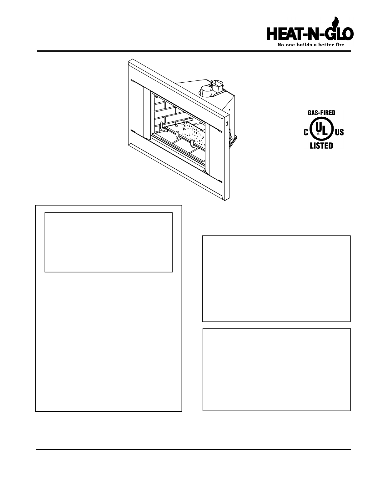
Model:
CFX-ZC
WARNING: IF THE INFORMATION
IN THESE INSTRUCTIONS IS NOT
FOLLOWED EXACTLY, A FIRE OR
EXPLOSION MAY RESULT CAUSING PROPERTY DAMAGE, PERSONAL INJURY, OR DEATH.
- Do not store or use gasoline or other flammable vapors and liquids in the vicinity of this
or any other appliance.
- What to do if you smell gas
• Do not try to light any appliance.
• Do not touch any electrical switch.
• Do not use any phone in your building.
• Immediately call your gas supplier from a
neighbor's phone. Follow the gas supplier's
instructions.
• If you cannot reach your gas supplier, call
the fire department.
- Installation and service must be performed by a
qualified installer, service agency, or the gas
supplier.
Installers Guide
Underwriters
Laboratories Listed
READ THIS MANUAL BEFORE INSTALLING OR
OPERATING THIS APPLIANCE. THIS INSTALLERS
GUIDE MUST BE LEFT WITH APPLIANCE FOR
FUTURE REFERENCE.
WARNING: IMPROPER INSTALLATION, ADJUSTMENT, ALTERATION,
SERVICE OR MAINTENANCE CAN
CAUSE INJURY OR PROPERTY DAMAGE. REFER TO THIS MANUAL. FOR
ASSISTANCE OR ADDITIONAL INFORMATION CONSULT A QUALIFIED INSTALLER, SERVICE AGENCY, OR THE
GAS SUPPLIER.
1. This appliance may be installed in an aftermarket, permanently located, manufactured
(mobile) home, where not prohibited by local codes.
2. This appliance is only for use with the type
of gas indicated on the rating plate. This
appliance is not convertible for use with
other gases, unless a certified kit is used.
Printed in U.S.A. Copyright 2003
Heat-N-Glo, a division of Hearth & Home Technologies Inc.
20802 Kensington Boulevard, Lakeville, MN 55044
This product is covered by one or more of the following patents: (United States) 4,112,913; 4,408,594; 4,422,426; 4,424,792; 4,520,791; 4,793,322;
4,852,548; 4,875,464; 5,000,162; 5,016,609; 5,076,254 5,191,877; 5,218,953; 5,328,356; 5,429,495; 5,452,708; 5,542,407; 5,613,487; (Australia)
543790; 586383; (Canada) 1,123,296; 1,297,746; 2,195,264; (Mexico) 97-0457; (New Zealand) 200265; or other U.S. and foreign patents pending.
Please contact your Heat-N-Glo dealer for any questions
or concerns. For the number of your nearest Heat-N-Glo
dealer, please call 1-888-427-3973.
567-900E 1/03
1
SAFETY AND WARNING INFORMATION
READ and UNDERSTAND all instructions carefully
!
before starting the installation. FAILURE TO
FOLLOW these installation instructions may result
in a possible fire hazard and will void the warranty.
Prior to the first firing of the fireplace, READ the
!
Using Your Fireplace section of the Owners Guide.
DO NOT USE this appliance if any part has been
!
under water. Immediately CALL a qualified service
technician to inspect the unit and to replace any part
of the control system and any gas control which has
been under water.
THIS UNIT IS NOT FOR USE WITH SOLID FUEL.
!
Installation and repair should be PERFORMED by a
qualified service person. The appliance and venting
!
system should be INSPECTED before initial use
and at least annually by a professional service
person. More frequent cleaning may be required
due to excessive lint from carpeting, bedding
material, etc. It is IMPERATIVE that the unit’s
control compartment, burners, and circulating air
passageways BE KEPT CLEAN to provide for
adequate combustion and ventilation air.
These units MUST use one of the vent systems
described in the Installing the Fireplace section of
!
the Installers Guide. NO OTHER vent systems or
components MAY BE USED.
This gas fireplace and vent assembly MUST be
!
vented directly to the outside and MUST NEVER be
attached to a chimney serving a separate solid fuel
burning appliance. Each gas appliance MUST USE
a separate vent system. Common vent systems are
PROHIBITED.
INSPECT the external vent cap on a regular basis to
!
make sure that no debris is interfering with the air
flow.
The glass door assembly MUST be in place and
!
sealed, and the trim door assembly MUST be in
place on the fireplace before the unit can be placed
into safe operation.
DO NOT OPERATE this appliance with the glass
!
door removed, cracked, or broken. Replacement of
the glass door should be performed by a licensed
or qualified service person. DO NOT strike or slam
the glass door.
Always KEEP the appliance clear and free from
!
combustible materials, gasoline, and other
flammable vapors and liquids.
NEVER OBSTRUCT the flow of combustion and
!
ventilation air. Keep the front of the appliance
CLEAR of all obstacles and materials for servicing
and proper operations.
Due to the high temperature, the appliance should
be LOCATED out of traffic areas and away from
!
furniture and draperies. Clothing or flammable
material SHOULD NOT BE PLACED on or near the
appliance.
Children and adults should be ALERTED to the
!
hazards of high surface temperature and should
STAY AWAY to avoid burns or clothing ignition.
Young children should be CAREFULLY SUPERVISED
when they are in the same room as the appliance.
The glass door assembly SHALL ONLY be
!
replaced as a complete unit, as supplied by the gas
fireplace manufacturer. NO SUBSTITUTE material
may be used.
DO NOT USE abrasive cleaners on the glass door
!
assembly. DO NOT ATTEMPT to clean the glass
door when it is hot.
Turn off the gas before servicing this appliance. It is
recommended that a qualified service technician
!
perform an appliance check-up at the beginning of
each heating season.
Any safety screen or guard removed for servicing
!
must be replaced before operating this appliance.
DO NOT place furniture or any other combustible
!
household objects within 36 inches of the fireplace
front.
2

TABLE OF CONTENTS
TABLE OF CONTENTS
Safety and Warning Information ............................................... 2
Safety and Warning Information ............................................... 2
Service Parts List ...................................................................... 4
Service Parts List ...................................................................... 4
u
Section 1: Approvals and Codes .............................................. 6
Section 1: Approvals and Codes .............................................. 6
Appliance Certification ................................................................. 6
Appliance Certification ................................................................. 6
Installation Codes ........................................................................ 6
Installation Codes ........................................................................ 6
u
High Altitude Installations.............................................................. 6
High Altitude Installations.............................................................. 6
Section 2: Getting Started ........................................................ 7
Section 2: Getting Started ........................................................ 7
Introducing the Heat-N-Glo Gas Appliances ................................. 7
Introducing the Heat-N-Glo Gas Appliances ................................. 7
Pre-installation Preparation.......................................................... 7
Pre-installation Preparation.......................................................... 7
Venting and Installation................................................................. 7
Venting and Installation................................................................. 7
Section 3: Installing the Insert ................................................. 9
Section 3: Installing the Insert ................................................. 9
Step 1 Installing the Vent System............................................. 9
Step 1 Installing the Vent System............................................. 9
Step 2 Positioning, Leveling, and Securing the Insert............. 13
Step 2 Positioning, Leveling, and Securing the Insert............. 13
Step 3 The Gas Control Systems .......................................... 13
Step 3 The Gas Control Systems .......................................... 13
Step 4 The Gas Supply Line .................................................. 13
Step 4 The Gas Supply Line .................................................. 13
Step 5 Gas Pressure Requirements...................................... 14
Step 5 Gas Pressure Requirements...................................... 14
Step 6 Wiring the Appliance ................................................... 14
Step 6 Wiring the Appliance ................................................... 14
Step 7 Installing Logs and Ember Material ............................. 15
Step 7 Installing Logs and Ember Material ............................. 15
Positioning the Logs ................................................... 15
Positioning the Logs ................................................... 15
Placing the Ember Material ......................................... 15
Placing the Ember Material ......................................... 15
Step 8 Installing Trim Surround .............................................. 15
Step 8 Installing Trim Surround .............................................. 15
Step 9 Before Lighting the Appliance...................................... 16
Step 9 Before Lighting the Appliance...................................... 16
Step 10 Lighting the Appliance ................................................. 16
Step 10 Lighting the Appliance ................................................. 16
After the Installation.................................................................... 16
After the Installation.................................................................... 16
Section 4: Maintaining and Servicing Your Appliance ........ 17
Section 4: Maintaining and Servicing Your Appliance ........ 17
u = Contains updated information.
3
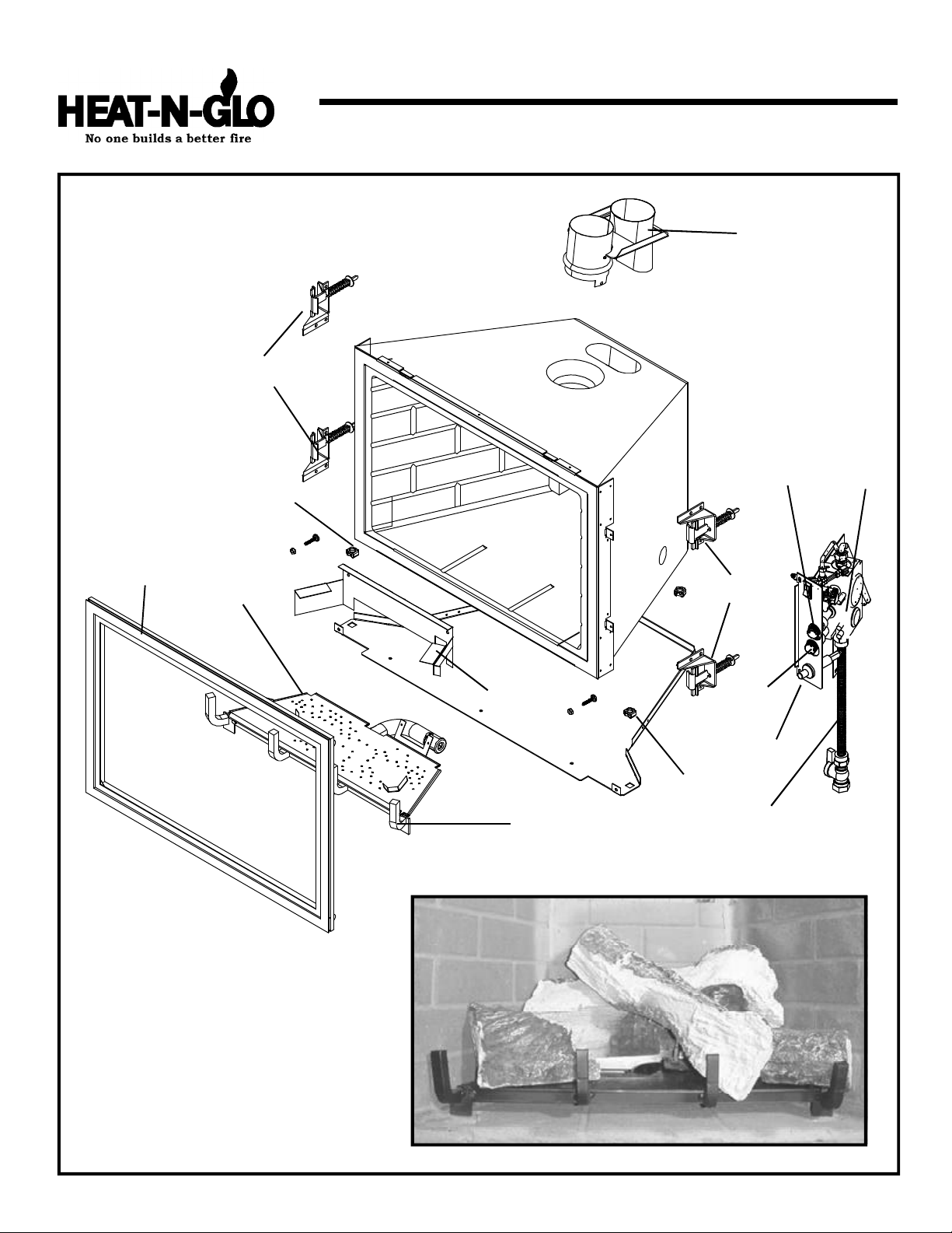
Service Parts
CFX-ZC
10
17
(NG, LP) Exploded Parts Diagram
(GN, PL) Vue éclatée des pièces
Beginning Manufacturing Date: 10-98
Ending Manufacturing Date: _______
12
13
1
4
3
16
10
14
2
17
11
15
5 Log Set Assembly
6
9
Part number list on following page.
*
La liste des numéros de pièce se trouve
*
à la page suivante.
7
4
8
(NG, LP) Service Parts List / Liste des pièces de rechange
CFX-ZC
IMPORTANT: THIS IS DATED INFORMATION. The most current information is located on your dealers VIP site. When
ordering, supply serial and model numbers to ensure correct service parts.
ITEM /
PIÈCE
COMMON PARTS / PIÉCES COMMUNES
SERIAL # /
N° DE SÉRIE
PART NUMBER
/ N° DE PIÈCE
1 SIT Valve NG / SIT Valve GN 571-500
1 SIT Valve LP / SIT Valve PL 571-501
Pilot Assembly - SIT NG / Module de veilleuse - SIT GN 571-510A
Pilot Assembly - SIT LP / Module de veilleuse - SIT PL 571-511A
2 Piezo Ignitor / Allumage Piézo 418-513
Burner Tube - 18" Flex / Tube de brûleur - 18" Flex 567-301A
Burner Orifice NG (#36B) / Orifice de brûleur GN (#36B) 567-801
Burner Orifice LP (#52B) / Orifice de brûleur PL (#52B) 074-801
3 Burner NG, LP (Includes grate assembly) / Brûleur GN, PL 567-276A
4 Glass Door Assembly / Module de Porte en verre GLA-CFX-ZC
5 Log Set Assembly / Jeu de Bûches LOGS-CFXZC
6 Log 1 / Bûche 1 SRV567-701
7 Log 2 / Bûche 2 SRV567-702
8 Log 3 / Bûche 3 SRV459-710
9 Log 4 / Bûche 4 SRV485-702
10 Glass Attachment Assembly / Module en verre 386-122A
11 Grate Assembly / Grille 567-361A
Conversion Kit NG / Module de conversion GN NGK-CFXZC
Conversion Kit LP / Module de conversion PL LPK-CFXZC
Pilot Orifice NG / Orifice de veilleuse GN 571-517
Pilot Orifice LP / Orifice de veilleuse PL 571-516
Thermopile / Thermopile 060-512
Thermocouple / Thermocouple 571-511
ON/OFF Rocker Switch / Interrupteur à bascule marche/arrêt 060-525A
Pilot Tube / Tube de veilleuse 510-309
12 Collar Assembly / Assemblée de Col 567-214A
13 Knob, ON/OFF / Bouton, "MARCHE/ARRÊT" 571-534
14 Knob, HI/LO / Bouton, HÉ/LO 571-533
15 Gas Line / Ligne du Gaz 302-320A
16 Log Bracket / Bûche Crochet 567-172
17 Leveling Bolts / Nivelage de Boulons(Verrous) 040-862
ACCESSORIES / ACCESSOIRES
Remote Control - Battery RC-BATT-HNG
Remote Control Temperature Read - Hand RC-SMART-HNG
Remote Control Digital Thermostat with Timer SMART-STAT-HNG
Wall Switch Kit, Off-white / Module d'interrupteur mural, Blanc Cassé WSK-21
Wall Switch Kit, White / Module d'interrupteur mural, Blanc WSK-21-W
3-Sided Matte Black with Polished Brass Trim, Dims 36" x 24" CFXZC-3624-3
3-Sided Matte Black with Polished Brass Trim, Dims 36" x 27" CFXZC-3627-3
4-Sided Matte Black with Polished Brass Trim, Dims 36" x 27 3/4" CFXZC-3627-4
Collar Adapter CFXZC-ADP
u
u
u
u
u
u
5
Approvals and
Codes
Appliance Certification
The Heat-N-Glo appliance models discussed in this
Installers Guide have been tested to certification standards
and listed by the applicable laboratories.
Certification
MODEL: CFX-ZC
LABORATORY: Underwriters Laboratories
TYPE: Direct Vent Gas Fireplace Heater
STANDARD: ANSI Z21.88•CSA2.33•UL307B
Installation Codes
The appliance installation must conform to local codes.
Before installing the appliance, consult the local building
code agency to ensure that you are in compliance with all
applicable codes, including permits and inspections.
In the absence of local codes, the fireplace installation must
conform to the National Fuel Gas Code ANSI Z223.1 (in the
United States) or the CAN/CGA-B149 Installation Codes
(in Canada). The appliance must be electrically grounded
in accordance with local codes or, in the absence of local
codes with the National Electric Code ANSI/NFPA No. 70
(in the United States), or to the CSA C22.1 Canadian Electric
Code (in Canada).
High Altitude Installations
U.L. Listed gas appliances are tested and approved without
requiring changes for elevations from 0 to 2,000 feet in the
U. S. A. and in Canada.
When installing this appliance at an elevation above 2,000
feet, it may be necessary to decrease the input rating by
changing the existing burner orifice to a smaller size. Input
rate should be reduced by 4% for each 1000 feet above a
2000 foot elevation in the U.S.A. or 10% for elevations
between 2000 and 4500 feet in Canada. If the heating value
of the gas has been reduced, these rules do not apply. To
identify the proper orifice size, check with the local gas
utility.
If installing this appliance at an elevation above 4,500 feet
(in Canada), check with local authorities.
u
These models may be installed in a bedroom or bed-sitting
room in the U.S.A. and Canada.
Heat-N-Glo Quality
Systems registered
by SGS ICS
6

Getting Started
Introducing the Heat-N-Glo Gas Appliances
Heat-N-Glo direct vent gas appliances are designed to
operate with all combustion air siphoned from outside of
the building and all exhaust gases expelled to the outside.
The information contained in this Installers Guide, unless
noted otherwise, applies to all models and gas control
systems. Gas appliance diagrams, including the dimensions,
are shown in this section.
Pre-install Preparation
This gas insert fireplace and its components are tested
and safe when installed in accordance with this Installers
Guide. Report to your dealer any parts damaged in shipment,
particularly the condition of the glass. Do not install any
unit with damaged, incomplete, or substitute parts.
The vent system components and trim surrounds are shipped
in separate packages. The gas logs are packaged
separately and must be field installed.
Read all of the instructions before starting the
installation. Follow these instructions carefully during
the installation to ensure maximum safety and benefit.
Failure to follow these instructions will void the
owner’s warranty and may present a fire hazard.
The Heat-N-Glo Warranty will be voided by, and Heat-N-Glo
disclaims any responsibility for, the following actions:
• Installation of any damaged fireplace or vent system
component.
• Modification of the fireplace or direct vent system.
• Installation other than as instructed by Heat-N-Glo.
• Improper positioning of the gas logs or the glass door.
• Installation and/or use of any component part not manufactured and approved by Heat-N-Glo, not withstanding
any independent testing laboratory or other party approval
of such component part or accessory.
ANY SUCH ACTION MAY POSSIBLY CAUSE A FIRE
HAZARD.
VENTING AND INSTALLATION
1. Heat -N-Glo gas inserts are designed for recessed in-
stallations into solid fuel Masonry or Factory Built Non
Combustible fireplaces that have been installed in accordance with the National, Provincial, State and local
building codes.
WARNING: Under no circumstances is cutting
!
of sheet metal surfaces allowed for installation.
If the factory built fireplace has no gas ac-
!
cess holes provided, an access hole of 1” diameter (25mm) or less may be drilled through the
lower sides or bottom of the combustion chamber in a proper workmanship like manner.
3. To assure top performance, safety and efficiency, inserts
must be installed with an approved flue liner as per CAN/
CGA B-149 or National Fuel Code ANSI Z223 and these
instructions.
WARNING: THE SOLID FUEL FIREPLACE HAS
!
BEEN CONVERTED FOR USE WITH GAS
ONLY AND CANNOT BE USED FOR BURNING
WOOD OR SOLID FUELS UNLESS ALL ORIGINAL
PARTS HAVE BEEN REPLACED AND THE FIREPLACE HAS BEEN REAPPROVED BY THE AUTHORITY HAVING JURISDICTION.
4. The solid fuel fireplace’s flue damper must be fully locked
in the open position or removed for installation.
5. The chimney must be cleaned and in good working order
and constructed of noncombustible materials.
6. Make sure that all chimney cleanouts fit properly so air
cannot leak into the chimney.
7. Install the insert without the trim surround and make all
gas, venting, and electrical connections.
8. Install decorative trim surround. Please refer to instructions included with the trim surround.
Ensure there are no obstructions to side air
!
passages by the decorative trim once it is installed on insert.
When planning a fireplace insert installation, it’s necessary
to determine:
• The vent system configuration to be used.
• Gas supply piping.
• Whether optional accessories—devices such as a wall
switch or remote control—are desired.
2. Minimum fireplace opening requirements are shown in
Figure 1 of this installation manual. The firebrick (refractory) can be removed from a factory built fireplace in order to gain minimum gas insert opening requirements.
7

11 (279mm)
5 1/2 (139mm)
16
(406mm)
(117mm)
(64mm)
5 1/2 (140mm)
23 (583mm)
27 1/4 (692mm)
17
16 1/8
(410mm)
2
(51mm)
13 3/4
(351mm)
(432mm)
16
(406mm)
TOP VIEW
OF FIREPLACE
28
(711mm)
Figure 1. Diagram of the CFX-ZC
2 1/2
4 5/8
MINIMUM FIREPLACE SIZE
FRONT WIDTH : 28” (71 1mm)
REAR WIDTH : 17” (432mm)
DEPTH : 16” (406mm)
HEIGHT : 16 1/4” (413mm)
*
NOTE: If exhaust collar on insert and
*
fireplace damper do not line up, add 4 inches
(102mm) to minimum fireplace height for
bends in vent pipe.
8

Installing the Insert
Step 1. Installing the Vent System
Vent System Installation Precautions
Before starting installation of vent kits, the installer should
read these instructions and the Vent Kit Instructions to
ensure that a proper vent installation is completed.
Consult your local building codes before beginning the
installation.
WARNING: THIS GAS INSERT AND VENT AS-
!
SEMBLY MUST BE VENTED DIRECTL Y TO THE
OUTSIDE AND MUST NEVER BE ATTACHED TO A
CHIMNEY SERVING A SEPARATE SOLID FUEL
BURNING APPLIANCE. EACH GAS APPLIANCE
MUST USE A SEP ARATE VENT SYSTEM. COMMON
VENT SYSTEMS ARE PROHIBITED.
Vent System Approvals
Model: Vent System
CFX-ZC LINK-DV30, LINK- DV4-30
Table 1
Table 1 and Figures 3 through 5 show the vent termination
caps and systems approved for use with these models.
Approved vent system terminations are labeled for identification. 3-inch diameter listed flexible aluminum and stainless steel gas vent is used for both the incoming combustion air and exhaust vent pipes. NO OTHER VENTING SYSTEMS OR COMPONENTS MAY BE USED. Detailed installation instructions are included with each vent termination kit and should be used in conjunction with this manual.
Horizontal Venting
The vent system on this model CANNOT be terminated
horizontally.
Vertical Venting
The vent pipes MUST be connected to the proper collars
on the unit AND the exhaust vent pipe MUST be connected
to the termination cap or the unit will not operate. The combustion air vent pipe CAN be connected to the termination
cap or it can terminate inside the chimney. The bottom
opening of the chimney must be sealed around the vent
pipes if the combustion air vent is NOT connected to the
termination cap. See Figures 3, 4 and 5.
NOTE: The minimum vertical rise (exhaust vent) is 14 feet
and the maximum vertical rise is 40 feet. These dimensions
are measured from the starting collars of the unit to the end
of the last section of vent pipe. See dimension V in Figure 3.
A vertical vent termination system installed on this model
will include one (1) length of 3-inch flexible vent pipe for the
combustion air, one (1) length of 3-inch flexible vent pipe for
the exhaust air, one (1) pipe-to-cap adaptor, and one (1)
SLK-991DA or SLK-980D Vertical Termination Cap.
NOTE: The damper of the masonry chimney may need to
be removed to allow installation of the flexible-vent pipe.
This fireplace has been altered to accommodate an
insert and should be inspected by a qualified person
prior to re-use as a conventional fireplace.
NOTE: The above label, located in the instruction package,
must be affixed to the existing fireplace prior to installation.
For zero clearance factory built woodburning fireplaces, the
use of kit LINK-ZC-ADP in place of the standard square
flashing will allow you to mount the adaptor and cap on
metal pipe. Additionally, the use of kit FLASH-DAMP will
seal off the damper opening when terminating the inlet air
vent pipe just above the damper. These 2 kits are
recommended for zero clearance, factory built woodburning
fireplaces.
Connecting the Vent Pipe
Install the 3” flexible vent pipe(s) down through the chimney.
Secure 3” collar to the end of the flexible vent pipe for exhaust
using 3 screws. Attach provided 3’ section of stainless steel
flexible vent pipe to this collar. Slide the gas insert into
place, and position any excess flexible vent pipe back up
into the chimney.
NOTE: The 3’ section of stainless steel flexible pipe may
be cut to aid installation provided that a minimum of 2’ is
maintained.
Using the provided T-handle pull down tool, reach through
exhaust opening in exhaust collar by its center pin. Pull
down until exhaust collar (or collar attachment bracket)
extends through exhaust opening. The collar should slip fit
through the molded 3 inch opening. Carefully readjust liners
to align if necessary.
Secure in place by sliding retainer pin through the provided
holes in the exhaust collar. See Figure 4.
9

HORIZONTAL OVERHANG
12XROOF PITCH IS X/ 12
H (MIN.) - MINIMUM HEIGHT FROM ROOF
WARNING: DO NOT FORCE
!
COLLAR ATTACHMENT INTO
PLACE. THE FIREPLACE IS MADE
OF A FRAGILE MATERIAL, AND
MAY BREAK. READJUST FLEXIBLE VENT PIPES IF NECESSARY.
Attach the pipe-to-cap adaptor to the
termination cap and to the top of the
flexible vent pipe and set the cap in place
at the top of the chimney. See Figures 3,
4 and 5.
CAUTION: TO AVOID DOWNDRAFTS
AND/OR COLD AIR PROBLEMS, IT IS
RECOMMENDED TO SEAL OFF THE
AREA BETWEEN THE TERMINATION
CAP AND THE TOP OF THE SOLIDFUEL CHIMNEY OPENING INTO
WHICH THE VENT CAP HAS BEEN INSTALLED.
WHEN USING THE LINK-DV4-3O VENT
SYSTEM, IT IS REQUIRED TO SEAL
AROUND THE FLEXIBLE VENT PIPES
IN THE DAMPER AREA. SEE FIGURE
3. USE FIBERGLASS INSULA TION OR
OTHER SUITABLE NON-COMBUSTIBLE MATERIAL.
WARNING: MAJOR U.S.
!
BUILDING CODES SPECIFY
MINIMUM CHIMNEY AND/OR VENT
HEIGHT ABOVE THE ROOF TOP.
THESE MINIMUM HEIGHTS ARE
NECESSARY IN THE INTEREST OF
SAFETY. SEE THE FOLLOWING
DIAGRAM FOR MINIMUM HEIGHTS,
PROVIDED THE TERMINA TION CAP
IS AT LEAST 2-FEET FROM A VERTICAL WALL AND 2-FEET BELOW
A HORIZONTAL OVERHANG.
TERMINATION CAP
2 FT.
MIN.
2 FT. MIN.
LOWEST
DISCHARGE
OPENING
TO LOWEST DISCHARGE OPENING
Roof Pitch H (min.) ft.
flat to 6/12 1.0
6/12 to 7/12 1.25
over 7/12 to 8/12 1.5
over 8/12 to 9/12 2.0
over 9/12 to 10/12 2.5
over 10/12 to 11/12 3.25
over 11/12 to 12/12 4.0
over 12/12 to 14/12 5.0
over 14/12 to 16/12 6.0
over 16/12 to 18/12 7.0
over 18/12 to 20/12 7.5
over 20/12 to 21/12 8.0
Figure 2. Minimum Height from Roof to Lowest
Discharge Opening
VERTICAL WALL
NOTE: This also pertains to vertical vent
systems installed on the outside of the
building.
10

This option shows both exhaust and inlet
TERMINATION
ADAPTOR
COLLAR
ATTACHMENT
V= 14FT. MINIMUM
50FT. MAXIMUM
BLOCK PIPE END WITH
OTHER SEALING MATERIAL
INLET AIR
VENT PIPE
air vent pipes attached to the adaptor.
TERMINATION CAP
ADAPTOR
EXHAUST
VENT PIPE
3 INCH COLLAR
WARNING: DO NOT
INSULATION OR ANY
STAINLESS STEEL
PIPE - 2 FT MIN.
REQUIRED (INCLUDED)
EXHAUST
COLLAR
CAP
INLET AIR
COLLAR
Figure 3.
WARNING: THE EXHAUST VENT PIPE MUST
!
ONLY BE CONNECTED TO THE EXHAUST
STARTING COLLAR OF THE UNIT AND THE
CENTER COLLAR OF THE TERMINA TION CAP .
A MINIMUM OF 2 FEET OF STAINLESS STEEL
!
FLEXIBLE LINER MUST BE ATTACHED
DIRECTLY TO THE EXHAUST COLLAR ON THE
COLLAR ATTACHMENT BRACKET.
BRACKET
11
THE INLET AIR PIPE MUST ONLY BE
!
CONNECTED TO THE INLET AIR COLLAR OF
THE UNIT AND EITHER ATTACHED TO THE
INLET AIR COLLAR OF THE TERMINATION CAP
OR TERMINA TED IN THE CHIMNEY .

TERMINATION
ADAPTOR
INLET AIR
STAINLESS STEEL
WITH INTERNAL CENTER PIN
INTAKE
3 INCH COLLAR
3 INCH
STAINLESS STEEL
FLEXIBLE VENT
COLLAR
ATTACHMENT
BRACKET
NOTE: INSPECT
FOR EXHAUST
COLLAR GASKET
TO INSURE
POSITIVE
EXHAUST SEAL.
EXHAUST
RETAINER PIN
T-HANDLE
PULL DOWN
TOOL
Figure 4. Stainless adapter for exhaust (required).
CENTER
PIN
SIDE VIEW
CAP
3 INCH COLLAR
NOTE: INSPECT
FOR EXHAUST COLLAR
GASKET TO INSURE
POSITIVE EXHAUST
SEAL.
EXHAUST
STARTING COLLAR
Figure 5. Typical configuration of vent liners.
FLEXIBLE PIPE
(PROVIDED)
INLET AIR
STARTING COLLAR
EXHAUST
COLLAR
COLLAR
12

Step 2. Positioning, Leveling, and
GAS VALVE
MANUAL SHUT OFF
Securing the Insert
• Place the insert into position.
• Level the insert from side to side and from front to back.
Use the leveling legs included with the manual
bag if necessary. Screw the legs into the nuts installed
in the bottom rear of the insert. Turn legs in until insert
is level.
Step 4. The Gas Supply Line
NOTE: Have the gas supply line installed in accordance
with local building codes by a qualified installer
approved and/or licensed as required by the locality.
(In the state of Massachusetts installation must be
performed by a licensed plumber or gas fitter).
NOTE: Before the first firing of the fireplace, the gas
supply line should be purged of any trapped air.
Step 3. The Gas Control System
WARNING: THIS UNIT IS NOT FOR USE WITH
!
SOLID FUEL.
This model uses a standing pilot ignition type of gas control
system.
Standing Pilot Ignition System
This system includes millivolt control valve, standing pilot,
thermopile/thermocouple flame sensor, and piezo ignitor.
WARNING: 110-120 VAC MUST NEVER BE
!
CONNECTED TO A CONTROL VALVE IN A
MILLIVOLT SYSTEM.
STANDING PILOT
NOTE: Consult local building codes to properly size
the gas supply line leading to the 1/2 inch (13 mm)
hook-up at the unit.
This gas fireplace is designed to accept a 1/2 inch
(13 mm) gas supply line. To install the gas supply line:
• A listed (and State of Massachusetts approved) 1/2 inch
(13mm) tee-handle manual shut-off valve and a listed
flexible gas connector are connected to the 1/2 inch
(13mm) inlet of the control valve. NOTE: If substituting
for these components, please consult local codes for
compliance.
• Locate the gas line access hole in the outer casing of
the fireplace.
• Open the lower grille, insert the gas supply line through
the gas line hole, and connect it to the shut-off valve.
• When attaching the pipe, support the control so that the
lines are not bent or torn.
• After the gas line installation is complete, use a soap
solution to carefully check all gas connections for leaks.
WARNING: DO NOT USE AN OPEN FLAME
!
TO CHECK FOR GAS LEAKS.
Figure 6. Gas Controls System
FLEX CONNECTOR
Figure 7. Gas Supply Line
13

Step 5. Gas Pressure Requirements
OPTIONAL WALL SWITCH
THERMOSTAT OR REMOTE
Pressure requirements for these gas appliances are shown
in the table below.
Pressure Natural Gas Propane
Minimum 5.0 inches 11.0 inches
Inlet Pressure w.c. w.c.
Maximum Inlet 14.0 inches 14.0 inches
Gas Pressure w.c. w.c.
Manifold 3.5 inches 10.0 inches
Pressure w.c. w.c.
A one-eighth (1/8) inch (3 mm) N.P.T. plugged tapping is
provided on the inlet and outlet side of the gas control for a
test gauge connection to measure the manifold pressure.
Use a small flat blade screwdriver to crack open the screw
in the center of the tap. Position a rubber hose over the tap
to obtain the pressure reading.
The fireplace and its individual shut-off valve must be
disconnected from the gas supply piping system during
any pressure testing of the system at test pressures in
excess of one-half (1/2) psig (3.5 kPa).
The fireplace must be isolated from the gas supply piping
system by closing its individual shut-off valve during any
pressure testing of the gas supply piping system at test
pressures equal to or less than one-half (1/2) psig (3.5 kPa).
Step 6. Wiring the Fireplace
NOTE: Electrical wiring must be installed by a licensed
electrician.
CAUTION: DISCONNECT REMOTE CONTROLS IF ABSENT FOR EXTENDED TIME PERIODS TO PREVENT
ACCIDENT AL APPLIANCE OPERATION.
For Standing Pilot Ignition Wiring
Appliance Requirements
• This appliance DOES NOT require 110-120 VAC to operate.
WARNING: DO NOT CONNECT 110-120 VAC
!
TO THE GAS CONTROL VALVE OR THE APPLIANCE WILL MALFUNCTION AND THE
VALVE WILL BE DESTROYED.
Wall Switch
Position the wall switch in the desired position on a wall.
Run a maximum of 25 feet (7.8 m) or less length of 18
A.W.G. minimum wire and connect it to the fireplace valve
pigtails.
WARNING: DO NOT CONNECT 110-120 VAC
!
TO THE WALL SWITCH OR THE CONTROL
VALVE WILL BE DESTROYED.
CAUTION: LABEL ALL WIRES PRIOR TO DISCONNECTION WHEN SERVICING CONTROLS. WIRING ERRORS
CAN CAUSE IMPROPER AND DANGEROUS OPERA TION.
VERIFY PROPER OPERATION AFTER SERVICING.
THERMOCOUPLE
GAS
VALVE
RED T1
Figure 8. Standing Pilot Ignition Wiring Diagram
THERMOPILE
WHITE T2
ON
OFF
ROCKER
SWITCH
14

Step 7. Installing Logs and Ember Material
EMBER
SURROUND
WITH TRIM
Positioning the Logs
If the gas logs have been factory installed they should not
need to be positioned.
If the logs have been packaged separately, refer to the
installation instructions that accompany the logs. Save
the log instructions with this manual.
If sooting occurs, the logs might need to be repositioned
slightly to avoid excessive flame impingement.
• Place a dime size piece of glowing ember material near
port holes in burner top, sides and front (see Figure 10).
Placing the Ember Material
Three separate bags of ember material are shipped with
this gas appliance. The bag labeled Golden Ember (GE-
93) is flame colorant material. The bags labeled Glowing
Ember (050-721) is standard glowing ember material.
To place the ember material:
• Open the left and right door panels on surround.
• Unlatch the latches at the right and left sides of the
glass door by pulling latch towards you and away from
fireplace (see Figure 9).
• Remove the glass door from the unit.
GLASS LATCH
PULL TO
UNLATCH
MATERIAL
Figure 10. Placement of the Ember Material
• Space ember pieces about a 1/2 inch apart.
• Never press embers into burner ports.
• Cover the top of the burner with a single layer of ember
material. Then sprinkle GE-93 (Golden Ember) on top of
the burner.
• Save the remaining ember materials for use during fireplace servicing. The embers provided are sufficient for 2
to 4 applications.
• Replace the glass door.
• Re-install and latch the glass door.
Step 8. Installing Trim Surrounds
Figure 9. Glass Assembly Latch
Combustible materials MUST NEVER overlap
onto the front face.
NOTE: REMOVE GLASS DOOR ASSEMBLY
FROM THE INSERT BEFORE SURROUND
INSTALLATION.
1. Find the coiled low voltage wires and ON/OFF
switch attached to outer right side of the insert
(Figure 11).
2. Disconnect the ON/OFF switch from the low
voltage wire leads, and insert the ON/OFF
switch through the hole at the upper right corner
of the surround - it will be retained in the hole.
FIREBOX
ON/OFF
SWITCH
SURROUND
Figure 11.
15

3. Reconnect the low voltage wires to the ON/OFF switch.
Step 9. Before Lighting the Appliance
4. Attach surround by lifting slightly above front fireplace
opening, such that surround hangs on top of the front
frame of the unit. The bottom should swing into place
such that studs (lower corners of unit) protrude through
slotted holes.
5. Secure in place with provided wing nuts.
NOTE: PLACE THE THREE INSULATION PIECES INTO
THE CAVITIES AT THE BACK OF THE SURROUND BEFORE POSITIONING THE INSERT INTO THE FACTORYBUILT OR MASONRY FIREPLACE. THIS INSULATION
WILL HELP SEAL FOR COLD AIR LEAKS.
12” MAX.
MANTEL
12” MIN.
Before lighting the appliance, be sure to do the following:
Remove all paperwork from underneath the fireplace.
Review safety warnings and cautions
• Read the Safety and Warning Information section at
the beginning of this Installers Guide.
Double-check for gas leaks
• Before lighting the appliance, double-check the unit for
possible gas leaks.
Double-check vent terminations for obstructions.
• Before lighting the appliance, double-check the unit for
possible obstructions that could be blocking the vent terminations.
Double-check for faulty components
• Any component that is found to be faulty MUST BE replaced with an approved component. Tampering with the
appliance components is DANGEROUS and voids all war-
ranties.
A small amount of air will be in the gas supply lines. When
first lighting the appliance, it will take a few minutes for the
lines to purge themselves of this air. Once the purging is
complete, the appliance will light and will operate normally.
TOP OF UNIT
Figure 12
Figure 12 shows the minimum vertical and corresponding
maximum horizontal dimensions of mantels or other combustible projections above the gas fireplace.
Subsequent lightings of the fireplace will not require this
purging of air from the gas supply lines, unless the gas
valve has been turned to the OFF position, in which
case the air would have to be purged.
NOTE: The fireplace should be run 3 to 4 hours on the initial
start-up. Turn it off and let it cool completely. Remove and
clean the glass. Replace the glass and run the fireplace for
an additional 8 hours. This will help to cure the chemicals
used in the paint and logs.
Step 10. Lighting the Appliance
You’ve reviewed all safety warnings, you’ve checked the
appliance for gas leaks, you know the vent system is
unobstructed, and you’ve checked for faulty components.
Now you’re ready to light the appliance.
WARNING: PLEASE REFER TO THE USER’S
!
MANUAL FOR ALL CAUTIONS, SAFETY , AND
WARNING INFORMATION PERTAINING TO THE
LIGHTING AND OPERATION OF THE APPLIANCE.
After the Installation
LEAVE THIS INSTALLATION MANUAL WITH
!
THE APPLIANCE FOR FUTURE REFERENCE.
16

Maintaining and Servicing Your Appliance
Appliance Maintenance
Although the frequency of servicing and maintenance will
depend on use and the type of installation, you should have
a qualified service technician perform an appliance checkup at the beginning of each heating season. See the table
below for specific guidelines regarding each fireplace maintenance task.
IMPORTANT: TURN OFF THE GAS BEFORE SERVICING
YOUR FIREPLACE.
Replacing old ember material
Frequency: Once annually, during the checkup.
By: Qualified service technician.
Task: Brush away loose ember material near the burner.
Replace old ember material with new dime-size and shape
pieces of Golden Ember (DE-93) and Glowing Ember (050-
721). New ember material should be placed alternately on
top of the burner - a layer of Golden Ember, a layer of
Glowing Ember, and so on. Save the remaining ember
material and repeat this procedure at your next servicing.
For more information, see Placing Ember Material.
Cleaning Burner and Controls
Frequency: Once annually.
By: Qualified service technician.
Task: Brush or vacuum the control compartment, fireplace
logs and burner areas surrounding the logs.
Checking Flame Patterns, Flame Height
Frequency: Periodically.
By: Qualified service technician/Home owner.
Task: Make a visual check of your fireplace’s flame patterns.
Make sure the flames are steady - not lifting or floating.
See Figure 13. The thermopile/thermocouple (standing pilot)
tips should be covered with flame. See Figure 6.
MAKE SURE THE FLAMES
ARE STEADY—NOT
LIFTING OR FLOATING.
Figure 13. Burner Flame Patterns
Checking Vent System
Frequency: Before initial use and at least annually
thereafter, more frequently if possible.
By: Qualified service technician/Home owner.
Task: Inspect the external vent cap on a regular basis to
ensure that no debris is interfering with the flow of air. Inspect
entire vent system for proper function.
Cleaning Glass Door
Frequency: After the first 3 to 4 hours of use. As neces-
sary after initial cleaning.
By: Home owner.
Task: Remove and clean glass after the first 3 to 4 hours of
use. After the initial cleaning, clean as necessary, particularly after adding new ember (flame colorant) material. Film
deposits on the inside of the glass door should be cleaned
off using a household glass cleaner. NOTE: DO NOT handle
or attempt to clean the door when it is hot and DO
NOT use abrasive cleaners.
17
 Loading...