

Heat-N-Glo
Underwriters Laboratories Listed
Installers Guide
Guide dinstallation
Model / Modèle:
CFX-36T
WARNING: If the information in
these instructions is not followed
exactly, a fire or explosion may result causing property damage, personal injury or death.
- Do not store or use gasoline or other
flammable vapors and liquids in the vicinity of this or any other appliance.
- WHA T TO DO IF YOU SMELL GAS:
• Do not try to light any appliance.
• Do not touch any electrical switch.
• Do not use any phone in your
building.
• Immediately call your gas supplier
from a neighbor's phone. Follow the
gas supplier's instructions.
AVERTISSEMENT: Si ces instructions ne sont pas suivies à la lettre,
un incendie ou une explosion
pourraient en résulter, causant des
dommages matériels, des blessures
ou la mort.
Nentreposez ou nutilisez jamais
dessence ou autres vapeurs et liquides
inflammables à proximité de cet appareil
ou de tout autre appareil.
QUE FAIRE SI VOUS SENTEZ UNE
ODEUR DE GAZ:
Ne tentez dallumer aucun appareil.
Ne touchez aucun interrupteur
électrique.
Nutilisez aucun téléphone dans votre
édifice.
Appelez immédiatement votre
fournisseur de gaz vous servant du
téléphone dun voisin. Suivez les instructions du fournisseur de gaz.
• If you cannot reach your gas supplier , call the fire department.
- Installation and service must be
performed by a qualified installer,
service agency , or the gas supplier.
Si vous ne pouvez pas atteindre votre
fournisseur de gaz, appelez le service
des incendies.
Linstallation et lentretien doivent être
effectués par un installateur qualifié, une
agence de maintenance ou le fournisseur de gaz.
1
492-900EFB 10/00
WARNING: Improper installation, adjustment, alteration, service or maintenance can cause injury or property
damage. Refer to this manual.
For assistance or additional information consult a qualified installer, service
agency or the gas supplier.
Read this manual before installing or
operating this appliance. This Installers
Guide must be left with appliance for
future reference.
AVERTISSEMENT: Une installation, un
réglage, une modification, une
réparation ou un service incorrects
risquent dentraîner des blessures ou
des dommages matériels. Consultez ce
manuel.
Pour obtenir de laide ou des informations supplémentaires, consultez un
installateur qualifié, une agence de
maintenance ou le fournisseur de gaz.
Lisez ce manuel avant dinstaller ou
dutiliser cet appareil. Ce Guide
dinstallation doit rester avec lappareil
pour référence ultérieure.
!
INFORMATION
!
!
!
!
!
!
SAFETY AND WARNING
READ and UNDERSTAND all instructions
carefully before starting the installation. FAILURE
TO FOLLOW these installation instructions may
result in a possible fire hazard and will void the
warranty.
Prior to the first firing of the fireplace, READ the
Using Your Fireplace section of the Owners Guide.
DO NOT USE this appliance if any part has been
under water. Immediately CALL a qualified
service technician to inspect the unit and to
replace any part of the control system and any
gas control which has been under water.
THIS UNIT IS NOT FOR USE WITH SOLID FUEL.
Installation and repair should be PERFORMED
by a qualified service person. The appliance and
venting system should be INSPECTED before
initial use and at least annually by a professional
service person. More frequent cleaning may be
required due to excessive lint from carpeting,
bedding material, etc. It is IMPERATIVE that the
units control compartment, burners, and
circulating air passageways BE KEPT CLEAN
to provide for adequate combustion and ventilation
air.
Always KEEP the appliance clear and free from
combustible materials, gasoline, and other
flammable vapors and liquids.
CONSIGNES DE SÉCURITÉ ET
!
MISES EN GARDE
LISEZ ATTENTIVEMENT toutes les instructions
!
avant de commencer linstallation. Si ces
instructions dinstallation ne sont pas suivies, un
risque dincendie pourrait en résulter et la garantie
sera annulée.
Avant lallumage initial, LISEZ la section du Guide
!
de lutilisateur intitulée Utilisation de votre foyer.
NUTILISEZ PAS cet appareil si une pièce a été
!
submergée. APPELEZ immédiatement un
technicien de service qualifié pour linspection de
lappareil et le remplacement de toute pièce qui
fut submergée.
CET APPAREIL NEST PAS CONÇU POUR
!
ÊTRE UTILISÉ AVEC DES COMBUSTIBLES
SOLIDES.
Linstallation et les réparations doivent être
!
EFFECTUÉES par un technicien de service
qualifié. Lappareil et le système dévacuation
doivent être INSPECTÉS avant la première
utilisation et au moins une fois lan par un
technicien professionnel. Un nettoyage plus
fréquent peut savérer nécessaire en cas
daccumulation de fibres de tapis, de literie, etc.
Il est IMPÉRATIF que le boîtier de commandes,
les brûleurs et les conduits dair de circulation de
lappareil RESTENT PROPRES afin de permettre
une circulation suffisante dair de combustion et
de ventilation.
Ne PLACEZ jamais de matériaux combustibles,
!
essence ou autres vapeurs ou liquides
inflammables à proximité de lappareil.
2
NEVER OBSTRUCT the flow of combustion and
!
ventilation air. Keep the front of the appliance
CLEAR of all obstacles and materials for servicing
and proper operations.
N’OBSTRUEZ JAMAIS
!
combustion et de ventilation. Maintenez l’avant de
l’appareil
d’en permettre le service et le bon fonctionnement.
DÉGAGÉ
de tout obstacle et matériau afin
la circulation d’air de
Due to the high temperature, the appliance should
!
be LOCATED out of traffic areas and away from
furniture and draperies. Clothing or flammable
material SHOULD NOT BE PLACED on or near
the appliance.
Children and adults should be ALERTED to the
!
hazards of high surface temperature and should
STAY AWAY to avoid burns or clothing ignition.
Young children should be CAREFULLY
SUPERVISED when they are in the same room
as the appliance.
These units MUST use one of the vent systems
!
described in the Installing the Insert section of
the Installers Guide. NO OTHER vent systems
or components MAY BE USED.
This gas fireplace and vent assembly MUST be
!
vented directly to the outside and MUST NEVER
be attached to a chimney serving a separate solid
fuel burning appliance. Each gas appliance MUST
USE a separate vent system. Common vent
systems are PROHIBITED.
INSPECT the external vent cap on a regular basis
!
to make sure that no debris is interfering with the
air flow.
DO NOT USE abrasive cleaners on the glass door
!
assembly. DO NOT ATTEMPT to clean the glass
door when it is hot.
Turn off the gas before servicing this appliance. It
!
is recommended that a qualified service
technician perform an appliance check-up at the
beginning of each heating season.
Any safety screen or guard removed for servicing
!
must be replaced before operating this appliance.
En raison de la température élevée, l’appareil doit
!
SE TROUVER
à bonne distance des meubles et des rideaux.
PLACEZ JAMAIS DE
inflammables sur l’appareil ou à proximité.
Les enfants et les adultes doivent être AVERTIS
!
des risques que présentent les surfaces à haute
température et doivent RESTER À L’ÉCART afin
d’éviter les brûlures et l’enflammement de
vêtements. Les enfants en bas âge doivent être
SURVEILLÉS ATTENTIVEMENT lorsqu’ils se
trouvent dans la même pièce que l’appareil.
Ces appareils
!
d’évacuation décrits dans la section intitulée
Installation de la cassette dans le
d’installation. AUCUN AUTRE
d’évacuation
Cet appareil à gaz et ce système d’évacuation
!
DOIVENT
directement à l’extérieur et
être raccordés à une cheminée desservant un autre
appareil à combustible solide. Chaque appareil à gaz
DOIT UTILISER
L’utilisation de systèmes d’évacuation en commun
est
INTERDITE
INSPECTEZ
!
ation extérieur afin de vous assurer que la circulation
de l’air ne soit pas entravée par des débris.
N’UTILISEZ PAS
!
sur la porte en verre.
la porte en verre lorsqu’elle est chaude.
Fermez le gaz avant d’effectuer le service de cet
!
appareil. Il est conseillé qu’un technicien de service
qualifié inspecte l’appareil au début de chaque saison
de chauffage.
en dehors des zones de passage et
vêtements OU matériaux
DOIVENT
NE PEUT ÊTRE UTILISÉ
évacuer les gaz de combustion
utiliser l’un des systèmes
système ou élément
.
NE DOIVENT JAMAIS
un système d’évacuation distinct.
.
régulièrement le capuchon d’évacu-
de produits d’entretien abrasifs
N’ESSA YEZ PAS
de nettoyer
NE
Guide
T ous les écrans et dispositifs de protection démontés
!
pour le service doivent être remis en place avant
l’utilisation de cet appareil.
3

Table of Contents
Table des matières
Safety and Warning Information ............................... 2
u
Service Parts List ........................................................5
Section 1: Approvals and Codes ............................... 7
Approval Listings and Codes ...........................................7
Appliance Certification ....................................................7
Installation Codes .......................................................... 7
High Altitude Installations ............................................... 8
Section 2: Getting Started ......................................... 9
Introducing the Heat-N-Glo Gas Fireplaces ...................... 9
Pre-installation Preparation .............................................9
Section 3: Installing the Fireplace ..........................12
Step 1 Locating the Fireplace .......................... 12
Step 2 Framing the Fireplace .......................... 13
Step 3 Negative Pressure Make-up Air............. 13
Step 4 Installing the Vent System ....................15
A. Vent System Approvals ........................ 15
B. System Components ........................... 15
C. Bedroom Installation in Canada ............ 20
D. Chimney Termination ............................ 20
Step 5 Positioning, Leveling, and
Securing the Fireplace ......................... 21
Step 6 The Gas Control System ...................... 21
Step 7 The Gas Supply Line ............................ 22
Step 8 Gas Pressure Requirements ................23
Step 9 Wiring the Fireplace ............................. 23
Step 10 Finishing .............................................. 25
Step 11 Installing Trim, Logs and
Ember Material .................................... 26
Installing the Trim ................................. 26
Positioning the Logs ............................ 27
Placing the Ember Material .................. 27
u
Installing Glass Doors ..........................27
Step 12 Before Lighting the Fireplace ................ 29
Step 13 Lighting the Fireplace ...........................29
After the Installation ........................................... 29
Section 4: Maintaining and Servicing
Your Fireplace ........................................ 30
Consignes de sécurité et mises en garde................. 2
u
List des pièces de rechange ...................................... 5
Section 1: Homologations et codes ......................... 7
Homologations et codes ................................................. 7
Homologation de lappareil .............................................. 7
Codes dinstallation ........................................................ 7
Installation à haute altitude ............................................. 8
Section 2: Comment débuter.................................... 9
Présentation des foyers à gaz Heat-N-Glo .......................9
Préparation avant linstallation ......................................... 9
Section 3: Installation du foyer .............................. 12
Étape 1 Emplacement du foyer .........................12
Étape 2 Encadrement du foyer ..........................13
Étape 3 Air de compensation en cas de
pression négative dans la pièce ............ 13
Étape 4 Installation du système dévacuation .....15
A. Homologation du système
dévacuation ......................................... 15
B. Éléments du système .......................... 15
C. Installation dans une chambre
à coucher au Canada ........................... 20
D. Terminaison de cheminée ..................... 20
Étape 5 Emplacement, nivellement et
solidification du foyer ............................ 21
Étape 6 Systèmes de commande de gaz .......... 21
Étape 7 Conduit à gaz ...................................... 22
Étape 8 Spécifications de la pression du gaz ..... 23
Étape 9 Filage électrique du foyer ...................... 23
Étape 10 Finition ............................................... 25
Étape 11 Installation de la garniture,
des bûches et des braises .................. 26
Installation de la garniture ................... 26
Mise en place des bûches ................. 27
Mise en place des braises .................. 27
u
Installation des portes en verre ........... 27
Étape 12 Avant dallumer le foyer ...................... 29
Étape 13 Allumage du foyer .............................. 29
Après linstallation ............................................. 29
Section 4: Entretien et service de votre foyer ....... 30
u = Contient des informations mises à jour.u = Contains updated information.
4

Service Parts
CFX-36T (NG) Exploded Parts Diagram / CFX-36T (GN) Vue éclatée des pièces
3
2
Part number list on following page.
*
La liste des numéros de pièce se trouve
*
à la page suivante.
1
11
4 Log Set Assembly
5
8
7
9
610
5
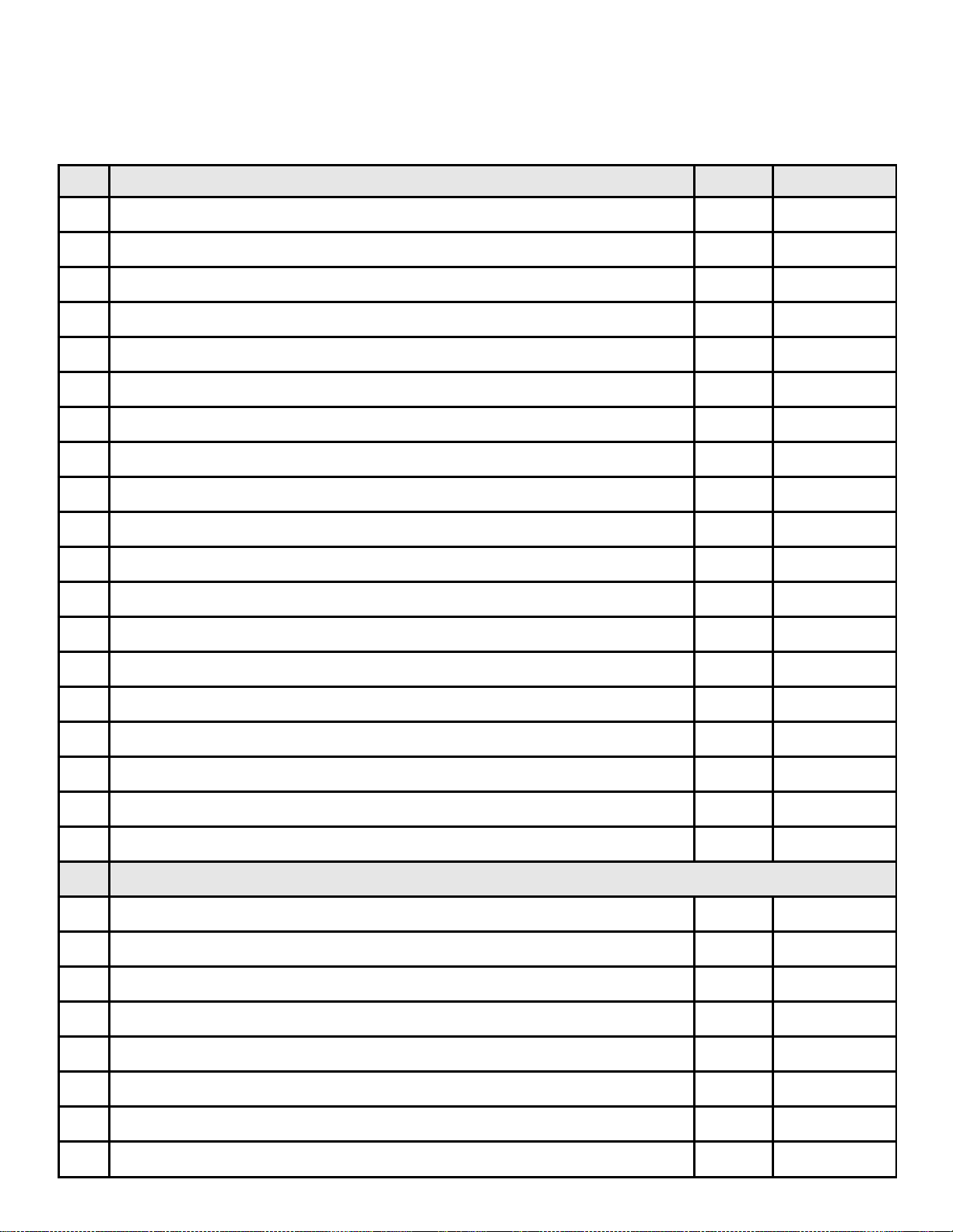
CFX-36T (NG) Service Parts List / CFX-36T (GN) Liste des pièces de rechange
IMPORTANT: THIS IS DATED INFORMATION. The most current information is located on your dealers VIP site. When ordering, supply serial and model numbers to ensure correct service parts. / IMPORTANT : L'information fournie dans cette brochure
n'est valide que pendant une courte période. Les sites VIP des distributeurs disposent des renseignements les plus récents.
Lors d'une commande, veuillez fournir les numéros de série et de modèles pour un remplacement adéquat des pièces.
ITEM /
PIÈCE
DSI IGNITION / ALLUMAGE DSI
SERIAL # /
N° DE S ÉRIE
PART NUMBER
/ N° DE PIÈCE
O N/OFF Wall Switch / Inter rupteur mural Marche/Arrêt 130-511
Wall Switch Cover Plate / Cache de l'interrupteur mural 130-512
High Temp Limit Switch / Interrupteur de détection thermique 066-531
Burner Orifice NG (#25) / Orifice de brûleur GN (#25) 492-800
Bimetallic Flue Damper / Registre de tuyau bimétallique 492-110A
1 Burner NG / Brûleur GN 492-710A
2 Grate / Grille 492-361
3 Refractory / Réfract aire SRV492-722
4 Log Set Assembly / Jeu de Bûches LOGS-CFX
5 Log 1 / Bûche 1 SRV492-701
6 Log 2 / Bûche 2 SRV492-702
7 Log 3 / Bûche 3 SRV492-703
8 Log 4 / Bûche 4 SRV492-704
9 Log 5 / Bûche 5 SRV446-706
10 Log 6 / Bûche 6 SRV446-704
11 Junction Box / Boîtier de raccordement 100-254A
Valve NG / Valve GN 492-500
Electrode / Électrode 501-591
Module / Module 501-592
ACCESSORIES / ACC ES SOIRES
Cabinet Doors / Portes à battant GDA-CFXT
Bi-Fold Glass Door / Porte en verre pliante GDA-CFXT-BF
Remote Control Kit / Commande à distance RC-STAT
Remote Control Kit / Commande à distance SMART-STAT
Mesh Assembly / Écran MESH-CFX
Manual Flue Damper / Registre de tuyan manuel 492-210A
Make-up Ai r Ki t / Module de prise d'air de compensation AK-CFX
LP Conversion Kit / Module de conversion au propane LPK-CFXT
6
1Approvals and Codes
Homologations et codes
Approvals Listing and Codes
Appliance Certification
The Heat-N-Glo fireplace models discussed in this Installers
Guide have been tested to certification standards and listed
by the applicable laboratories.
CERTIFICATION STANDARD
MODEL CFX-36T
LABORATORY Underwriters Laboratories
TYPE Vented Decorative
STANDARD ANSIZ21.50CGA2.22
Installation Codes
The fireplace installation must conform to local codes. Before
installing the fireplace, consult the local building code agency
to ensure that you are in compliance with all applicable
codes, including permits and inspections. In the absence of
local codes, the fireplace installation must conform to the
National Fuel Gas Code ANSI Z223.1 (in the United States)
or the CAN/CGA-B149 Installation Codes (in Canada). The
appliance must be electrically grounded in accordance with
local codes or, in the absence of local codes with the National
Electric Code ANSI/NFPA No. 70 (in the United States), or
to the CSA C22.1 Canadian Electric Code (in Canada).
This model (natural gas and propane) can be installed in a
bedroom (in the United States) which has a total volume of
unconfined space appropriate to the particular installation.
Refer to the National Fuel Gas Code ANSI Z223.1/NFPA54
(current edition), the Uniform Mechanical Code (current
edition), and local Building Officials for the options allowed
in obtaining an effective bedroom volume of unconfined space.
This model (natural gas and propane) can be installed in a
bedroom (in Canada) if a thermostat (Model WH-STAT) is
installed with the unit. Consult local code authorities. Detailed
installation instructions for Model WH-STAT are included with
the kit.
Homologations et codes
Homologation de lappareil
Les modèles de foyer Heat-N-Glo dont il est question dans
ce Guide dinstallation ont été testés conformément aux
normes dhomologation et ont été approuvés par les
laboratoires compétents.
NORME DHOMOLOGATION
MODÈLES CFX-36T
LABORATOIRE Underwriters Laboratories
TYPE Foyer décoratif à système
dévacuation
NORMES ANSIZ21.50CGA2.22
Codes dinstallation
Linstallation du foyer doit être conforme aux codes locaux.
Avant dinstaller le foyer, consultez les autorités locales en
matière de codes de construction afin de vous assurer que
vous respectez tous les codes en vigueur, y compris les
permis de construire et les inspections. En labsence de
codes locaux, linstallation du foyer doit être conforme au
code américain National Fuel Gas Code ANSI Z223.1 (aux
États-Unis) ou aux Codes des installations CAN/CGA-B149
(au Canada). Lappareil doit être muni dun fil de terre
conformément aux codes locaux ou, en labsence de codes
locaux, au code américain National Electric Code ANSI/
NFPA n°70 (aux États-Unis) ou au Code électrique canadien
CSA C22.1 (au Canada).
Ce modèle (gaz naturel et propane) peut être installé dans
une chambre à coucher (aux États-Unis) ayant un volume
total despace libre adéquat pour linstallation en question.
Reportez-vous au code américain National Fuel Gas Code
ANSI Z223.1/NFPA54 (édition en vigueur). Consultez The
Uniform Mechanical Code (édition en vigueur) et les autorités
locales en matière de construction pour connaître les options
autorisées afin dobtenir un volume despace libre suffisant
dans une chambre à coucher.
Ce modèle (gaz naturel et propane) peut être installé dans
une chambre à coucher (au Canada) si un thermostat (modèle
WH-STAT) est installé avec lappareil. Consultez les autorités
locales. Des instructions détaillées dinstallation du modèle
WH-STAT sont incluses avec le module.
7
Approvals and Codes (continued)
Homologations et codes (suite)
High Altitude Installations
U.L. Listed fireplaces are tested and approved for elevations
from 0 to 2,000 feet in the U.S.A. and are tested and approved
for elevations from 0 to 4,500 feet in Canada.
When installing this fireplace at an elevation above 2,000
feet (in the United States), it may be necessary to decrease
the input rating by changing the existing burner orifice to a
smaller size. Input should be reduced four percent (4%) for
each 1,000 feet above sea level, unless the heating value of
the gas has been reduced, in which case this general rule
will not apply. To identify the proper orifice size, check with
the local gas utility.
When installing this fireplace at an elevation between 2,000
and 4,500 feet (in Canada), the input rating must be reduced
by ten percent (10%).
When installing this fireplace at an elevation above 4,500
feet (in Canada), check with local authorities. Consult your
local gas utility for assistance in determining the proper
orifice for your location.
Installation à haute altitude
Les foyers homologués U.L. ont été testés et approuvés
pour fonctionner entre 0 et 610 mètres daltitude aux ÉtatsUnis et entre 0 et 1.370 mètres daltitude au Canada.
Si ce foyer est installé à une altitude supérieure à 610 mètres
(aux États-Unis), il peut savérer nécessaire de réduire
ladmission du gaz en diminuant louverture de lorifice du
brûleur. Ladmission doit être réduite de quatre pour cent
(4%) par 305 mètres au-dessus du niveau de la mer, à moins
que le pouvoir calorifique du gaz ait été réduit. Dans ce cas,
cette règle générale ne sapplique pas. Pour connaître
louverture de lorifice qui convient, consultez le service local
de distribution de gaz.
Si ce foyer est installé entre 610 et 1.370 mètres daltitude
(au Canada), ladmission du gaz doit être réduite de dix
pour cent (10%).
Si ce foyer est installé à une altitude supérieure à 1.370
mètres (au Canada), consultez les autorités locales.
Consultez votre service local de distribution de gaz afin de
déterminer le diamètre de lorifice requis pour votre région.
8
2
Getting Started
Comment débuter
Introducing the
Heat-N-Glo Gas Fireplaces
These gas fireplaces are designed to operate with all exhaust gases expelled to the outside of the building. The vent
system for these fireplaces must be 8-inch Class A chimney as shown in the venting section of this manual.
The information contained in this Installers Guide, unless
noted otherwise, applies to all models and gas control systems. Gas fireplace diagrams, including the dimensions, are
shown in this section.
Pre-installation Preparation
This gas fireplace and its components are tested to perform
only when installed in accordance with this Installers Guide.
Report to your dealer any parts damaged in shipment,
particularly the condition of the glass. Do not install any
unit with damaged, incomplete, or substitute parts.
WARNING: THESE FIREPLACES ARE FACTORY
!
EQUIPPED FOR NATURAL GAS ONLY. PROPANE CONVERSION COMPONENTS AND INSTRUCTIONS ARE INCLUDED IN THE LPK-CFXT
PROPANE CONVERSION KIT. THIS CONVERSION MUST BE DONE IF YOU INTEND TO OPERATE THE CFX-36T WITH PROPANE.
The vent system components are shipped in separate packages.
The gas logs are shipped with the unit and installed per log
instructions. Read all of the instructions before starting
the installation. Follow these instructions carefully
during the installation to ensure maximum safety and
benefit. Failure to follow these instructions will void
the owners warranty and may present a fire hazard.
WARNING: IF THERE IS ANY NOTICEABLE DAM-
!
AGE TO THE FIBER FIREBOX PLEASE CONTACT
YOUR DEALER FOR FURTHER INSTRUCTIONS.
Présentation des
foyers à gaz Heat-N-Glo
Ces foyers à gaz sont conçus pour expulser tous les gaz de
combustion en dehors de lédifice. Ces foyers doivent
comporter, comme système dévacuation, une cheminée de
catégorieA, de 203mm, telle que celle qui est représentée
dans la section de ce manuel sur le système dévacuation.
Les informations contenues dans ce Guide dinstallation, sauf
dans le cas de mention contraire, sappliquent à tous les
modèles et à tous les systèmes de commande de gaz. Cette
section comprend des schémas du foyer, avec ses dimensions.
Préparation avant linstallation
Ce foyer à gaz et ses éléments ont été testés pour être utilisés
seulement dans des conditions dinstallation conformes à ce
Guide dinstallation. Signalez à votre concessionnaire toutes
pièces endommagées lors du transport, en particulier sil
sagit de la porte en verre. Ninstallez aucun appareil dont
des pièces sont endommagées, sont incomplètes ou
ont été remplacées par des pièces différentes.
AVERTISSEMENT: CES FOYERS SONT
!
ÉQUIPÉS EN USINE POUR FONCTIONNER
UNIQUEMENT AVEC DU GAZ NATUREL. LES
ÉLÉMENTS ET LES INSTRUCTIONS DE CONVERSION AU PROPANE SONT INCLUS DANS
LE MODULE DE CONVERSION AU PROPANE
LPK-CFXT. CETTE CONVERSION DOIT ÊTRE
EFFECTUÉE SI VOUS SOUHAITEZ UTILISER DU
PROPANE AVEC LE FOYER CFX-36T.
Les éléments du système dévacuation sont expédiés dans
différents colis. Les bûches à gaz sont expédiées avec
lappareil et doivent être installées conformément aux instructions qui sy rapportent. Lisez toutes les instructions
avant de commencer linstallation. Suivez
attentivement ces instructions pendant linstallation afin
dassurer une sécurité et une efficacité optimales. Si
ces instructions ne sont pas suivies, la garantie sera
annulée et vous pourriez causer un incendie.
AVERTISSEMENT: SI LE FOYER EN FIBRES
!
EST VISIBLEMENT ENDOMMAGÉ, VEUILLEZ
CONTACTER VOTRE DISTRIBUTEUR, QUI VOUS
EXPLIQUERA LES MESURES À PRENDRE.
9
Getting Started (continued)
Comment débuter (suite)
The Heat-N-Glo Warranty will be voided by, and Heat-N-Glo
disclaims any responsibility for, the following actions:
Installation of any damaged fireplace or vent system com-
ponent.
Modification of the fireplace or vent system.
Installation other than as instructed by Heat-N-Glo.
Improper positioning of the gas logs or the glass doors.
Installation and/or use of any component part not manu-
factured and approved by Heat-N-Glo, not withstanding
any independent testing laboratory or other party approval of
such component part or accessory.
ANY SUCH ACTION MAY POSSIBLY CAUSE A FIRE HAZARD.
When planning a fireplace installation, its necessary to
determine:
Where the unit is to be installed.
The vent system configuration to be used.
Gas supply piping.
La garantie Heat-N-Glo sera annulée par les actes suivants,
pour lesquels Heat-N-Glo décline toute responsabilité:
Installation déléments endommagés dans le foyer ou dans
le système dévacuation.
Modification du foyer ou du système dévacuation.
Installation différente de celle indiquée par Heat-N-Glo.
Placement incorrect des bûches à gaz ou de la porte en
verre.
Installation et/ou utilisation de pièces nayant pas été
fabriquées et approuvées par Heat-N-Glo, même si cette
pièce ou cet accessoire a été homologué par un laboratoire
dessais indépendant ou un autre organisme compétent.
CES ACTES POURRAIENT CAUSER UN INCENDIE.
Avant de commencer linstallation du foyer, il est nécessaire
de déterminer:
Lemplacement de lappareil.
La configuration du système dévacuation qui sera utilisée.
La tuyauterie dalimentation en gaz.
Electrical wiring.
Framing and finishing details.
Whether optional accessoriesdevices such as a remote
controlare desired.
If the fireplace is to be installed on carpeting or tile, or on any
combustible material other than wood flooring, the fireplace
should be installed on a metal or wood panel that extends
the full width and depth of the fireplace.
Le filage électrique.
Les détails dencadrement et de finition.
Si vous désirez installer des accessoires facultatifs
(dispositifs tels quune commande à distance).
Si le foyer doit être installé sur du tapis, du carrelage ou des
matériaux combustibles autres que du parquet en bois, il
doit être installé sur une plaque métallique ou un panneau
en bois aux dimensions du foyer.
10

Getting Started (continued)
Comment débuter (suite)
Figure 1. Diagram of CFX-36T
Figure 1. Schéma du foyer CFX-36T
11

3
Installing the Fireplace
Installation du foyer
Step 1
Locating the Fireplace
The diagram below shows space and clearance requirements
for locating a fireplace within a room.
Clearance
Requirements
The top, back, and sides of
the fireplace are defined by
stand-offs.
The minimum clearance to a
perpendicular wall extending
past the face of the fireplace is
one inch (25 mm).
The back of the fireplace may
be recessed 19 1/4 inch
(48.9cm) into combustible
construction.
Minimum Clearances from
the Class A Chimney Vent
Pipe to Combustible Materials is 2 inches (51mm) all
around the pipe.
The distance from the unit to
combustible constructions is
to be measured from the unit
outer wrap surface to the combustible construction, NOT
from the screw heads that
secure the unit together.
Figure 2.
Dimensions, Location and
Space Requirements
Étape 1
Emplacement du foyer
Le schéma ci-dessous indique les spécifications de
dégagement à respecter dans le choix de lemplacement
du foyer dans une pièce.
Spécifications de
dégagement
Le dégagement au-dessus, à
larrière et sur les côtés du
foyer est défini par des
entretoises.
Le dégagement minimal entre le foyer et un mur perpendiculaire dépassant la façade
du foyer est de 25mm.
Larrière du foyer peut être
encastré de 48,9cm dans une
structure combustible.
Le dégagement minimal
entre le conduit de cheminée de catégorieA et les
matériaux combustibles
est de 51mm tout autour
du conduit.
La distance entre lappareil et
toute structure combustible
doit être mesurée de la
surface de la paroi extérieure
de lappareil à la structure
combustible, et NON PAS
depuis les têtes de vis qui
assemblent les différentes
Figure 2.
Dimensions, emplacement
et spécifications de dégagement
parties de lappareil.
Minimum Clearances
from the Fireplace to Combustible Materials
Inches/ m m
Glass Front 36 914 Porte en verre
Floor 0 0 Plancher
Back 1/2 13 Arrière
Sides 1/2 13 Côtés
Top *4 *102 Dessus
Ceiling** 50 1270 Plafond**
*Using supplied non-combustible board on top of front face.
** The clearance to the ceiling is measured from the top of
the unit, excluding the standoffs and collar.
12
entre le foyer et les matériaux combustibles
* Avec la plaque non combustible fournie sur la façade.
** Le dégagement entre lappareil et le plafond se mesure à
partir du dessus de lappareil, à lexclusion des entretoises
et du collet.
Dégagement minimal

Installing the Fireplace
(continued)
Installation du foyer (suite)
Step 2
Framing the Fireplace
Fireplace framing can be built before or after the fireplace is
set in place. Framing should be positioned to accommodate
wall coverings and fireplace facing material. The diagram
below shows framing reference dimensions.
CAUTION:
MEASURE FIREPLACE DIMENSIONS, AND VERIFY
FRAMING METHODS AND WALL COVERING DETAILS,
BEFORE FRAMING CONSTRUCTION BEGINS.
Framing should be constructed of 2 X 4 lumber
or heavier. If using heavier framing you may
need to cut away, to meet 2 inch (51mm) clearance around vent pipe.
(Lencadrement doit être construit en bois de 5
X 10cm ou plus. Si vous utilisez une boutisse
plus grosse, vous aurez peut-être besoin de la
découper, afin de laisser un dégagement de
51mm autour du conduit dévacuation.)
Étape 2
Encadrement du foyer
Lencadrement du foyer peut être construit avant ou après
la mise en place du foyer. Lemplacement de lencadrement
doit laisser suffisamment despace pour les revêtements
du mur et du foyer. Le schéma ci-dessous indique les
dimensions de référence de lencadrement.
ATTENTION: MESUREZ LES DIMENSIONS DU FOYER
ET VÉRIFIEZ LES MÉTHODES DENCADREMENT,
AINSI QUE LES DÉTAILS CONCERNANT LE
REVÊTEMENT MURAL, AVANT DE COMMENCER LA
CONSTRUCTION DE LENCADREMENT.
Inches (mm)
Model A B C D
CFX-36T 36 3/4 35
(933 mm) (910 mm) (489 mm) (760 mm)
Figure 3. Framing Dimensions
NOTE: You must place the supplied (required) non-com-
bustible board on the top front face of the unit once the unit
is in place. See Figure 12.
13/16
19 1/4 29 15/16
Step 3
Negative Pressure Make-up Air
Negative Pressure Warning: When negative pressure is
present, an atmospherically vented fireplace may not
function properly and it may down draft. In the case of a
gas appliance, spillage of the combustion gases may occur.
This may create a dangerous carbon monoxide
situation in the house.
Figure 3. Dimensions de lencadrement
REMARQUE: Une fois lappareil en place, vous devez
placer, sur la façade supérieure de lappareil, la plaque non
combustible (exigée) qui est fournie. Voir Figure12.
Étape 3
Air de compensation en cas de
pression négative dans la pièce
Avertissement en cas de pression négative dans la
pièce: En cas de pression négative, un foyer à système
dévacuation atmosphérique risque de ne pas fonctionner
correctement et le tirage peut être inversé. Dans le cas
dappareils à gaz, léchappement des gaz de combustion
pourrait se produire. Cette situation risque dentraîner
un taux dangereux de monoxyde de carbone dans la
maison.
13

Installing the Fireplace (continued)
Installation du foyer (suite)
The causes of negative pressure to a house can include the
following:
Stack effect in the building.
Exhaust only appliances (mechanically and atmospheri-
cally vented).
Inadequate make-up air (which is increasingly more
prevalent in new construction).
THIS UNIT DOES CONTAIN A HIGH TEMPERATURE
LIMIT SWITCH THAT WILL TURN OFF THE FIREPLACE IF THE FLUE DAMPER IS NOT OPEN OR IN
A NEGATIVE PRESSURE SITUATION.
Negative Air Pressure Within the Structure:
This fireplace will operate correctly only if adequate ventilation is provided to allow proper draft to the fireplace system.
Heat-N-Glo assumes no responsibility for the improper performance of the fireplace system caused by inadequate draft
due to environmental conditions, down drafts, tight sealing
construction of the structure, or mechanical exhausting devices which create a negative air pressure within the structure where the fireplace is located.
It is recommended that
all natural venting nonair tight gas fireplaces
have outside air connected to them. It is
also recommended that
the building be mechanically or passively balanced to allow atmospherically vented appliances, such as atmospherically vented gas
fireplaces, to draft properly. If the home experiences negative pressure
or is likely to experience
negative pressure, connection to an outside air
source is mandatory.
Figure 4. Make-up Air
Installing Outside Make-up Air:
This unit is equipped to accept outside air. It is RECOMMENDED that an AK-CFX air kit be used with this appli-
ance. The 4-inch (102mm) side collar for the air kit will
come mounted to the fireplace. See Figure 4.
This appliance also contains a make-up air damper which is
manually opened and closed from inside of the firebox. Pull
forward to open, push back to close. See Figure 4.
CAUTION: DO NOT OPERATE THE AIR DAMPER WHEN
UNIT IS HOT.
Les causes de pression négative dans une résidence peuvent
inclure les conditions suivantes:
Effet de cheminée dans lédifice.
Appareils à système (mécanique et atmosphérique)
dévacuation ne possédant pas de prise dair de
compensation.
Air de compensation insuffisant (ce qui est de plus en
plus courant dans les édifices récents).
CET APPAREIL EST ÉQUIPÉ DUN INTERRUPTEUR
DE DÉTECTION THERMIQUE QUI ÉTEINDRA LE
FOYER SI LE REGISTRE DU TUYAU NEST PAS
OUVERT, OU EN CAS DE PRESSION NÉGATIVE.
Decompression À Lintérieur De La Structure:
Ce foyer fonctionne correctement uniquement avec une aération
adéquate pour permettre larrivée dun flux dair approprié dans
le foyer. Heat-N-Glo dégage toute responsabilité en cas de
mauvaises performances du foyer, provoquées par un flux dair
inadéquat dû aux conditions environnementales, une rupture
de tirage, la construction étanche de la structure ou des
systèmes dévacuation mécaniques qui créent une
décompression à lintérieur de la structure où se trouve le foyer.
Il est conseillé que tous les foyers à gaz non-hermétiques à
évacuation naturelle
soient munis dune prise
dair extérieur. Il est
également conseillé que
la pression de lédifice
soit mécaniquement ou
passivement équilibrée
afin que les appareils à
système dévacuation
atmosphérique, tels que
les foyers à gaz à
système dévacuation
atmosphérique, tirent
correctement. Si des
pressions négatives se
produisent chez vous,
ou sil risque de sen
produire, il est
obligatoire de raccorder
Figure 4. Air de compensation
le foyer à une source
dair extérieur.
Installation dune prise dair de compensation
extérieur:
Cet appareil est conçu de façon à pouvoir accepter une prise
dair extérieur. Il est CONSEILLÉ dutiliser un module de
prise dair extérieur AK-CFX avec cet appareil. Le collet latéral
de 102mm, prévu pour le raccord du module de prise dair
extérieur, est fixé en usine sur le foyer. Voir Figure4.
Cet appareil comprend également un registre dair de compensation qui souvre et se ferme manuellement de lintérieur
du foyer. Tirez pour ouvrir, poussez pour fermer. Voir Figure4.
ATTENTION: NACTIONNEZ PAS LE REGISTRE DAIR
LORSQUE LAPPAREIL EST CHAUD.
14

Installing the Fireplace (continued)
Installation du foyer (suite)
WARNING: IN A NEGATIVE PRESSURE CON-
!
DITION (LIKELY TO OCCUR IN NEW HOMES
THAT DO NOT HAVE ADEQUATE MAKE-UP
AIR) THE OUTSIDE AIR KIT MUST BE INSTALLED
TO OBTAIN PROPER PERFORMANCE AND TO HELP
PREVENT SPILLAGE OF COMBUSTION GASES.
Detailed installation instructions for Model AK-CFX Outside
Air kit are found in the kit. Follow these instructions to complete the installation.
Step 4
Installing the Vent System
A. Vent System Approvals
This model is approved to use Heat-N-Glo H300 or Heatilator
300 2-wall Series 8-inch Class A Chimney ONLY. NO OTHER
VENT CAN BE USED. NOTE: The installer MUST refer to
the installation procedure included with the approved chimney system used. The chimney MUST be installed according to its instructions.
AVERTISSEMENT: EN CAS DE PRESSION
!
NÉGATIVE (SITUATION SUSCEPTIBLE DE SE
PRODUIRE DANS LES MAISONS NEUVES OÙ
LAIR DE COMPENSATION EST INSUFFISANT), LE
MODULE DE PRISE DAIR EXTÉRIEUR DOIT ÊTRE
INSTALLÉ POUR OBTENIR DES PERFORMANCES SATISFAISANTES ET EMPÊCHER LÉCHAPPEMENT
DES GAZ DE COMBUSTION.
Les instructions détaillées dinstallation du module de prise
dair extérieur modèle AK-CFX accompagnent le module.
Suivez ces instructions pour effectuer linstallation.
Étape 4
Installation du système dévacuation
A. Homologation du système dévacuation
Ce modèle est approuvé pour un raccordement à une
cheminée de catégorieA de 203mm, de série Heat-N-Glo
H300 ou Heatilator 300 à double paroi SEULEMENT. AUCUN
AUTRE SYSTÈME DÉVACUATION NE PEUT ÊTRE
UTILISÉ. REMARQUE: Linstallateur DOIT consulter la
procédure dinstallation incluse avec le système dévacuation
approuvé utilisé. La cheminée DOIT être installée
conformément aux instructions qui laccompagnent.
B. System Components
Chimney System Configuration
MAXIMUM TOTAL VERTICAL OFFSET = 15 FT.
MINIMUM TOTAL VERTICAL RISE = 10 FT.
MAXIMUM TOTAL VERTICAL RISE = 60 FT.
MAXIMUM NO. OF OFFSET/RETURN PAIRS: 2-30o or 4-15
MAXIMUM UNSUPPORTED CHIMNEY LENGTH
BETWEEN OFFSET/RETURN = 6 FT.
Plan and install the chimney system using the parameters
shown above.
WARNING: YOU MUST NOT EXCEED THESE
!
PARAMETERS.
B. Éléments du système
Configuration du système dévacuation
DÉVOIEMENT VERTICAL TOTAL MAXIMAL = 457cm.
LONGUEUR VERTICALE TOTALE MINIMALE = 305cm.
LONGUEUR VERTICALE TOTALE MAXIMALE = 18,3m.
o
NOMBRE MAXIMAL DE PAIRES DE PIÈCES DE
DÉVOIEMENT/REDRESSEMENT: 2 de 30o ou 4 de 15
LONGUEUR MAXIMALE DE CHEMINÉE NON SOUTENUE
ENTRE LES PAIRES DE PIÈCES DE DÉVOIEMENT/
REDRESSEMENT = 183cm.
Préparez et effectuez linstallation du système dévacuation
en utilisant les paramètres ci-dessus.
AVERTISSEMENT: VOUS NE DEVEZ PAS
!
DÉPASSER CES PARAMÈTRES.
o
15

Installing the Fireplace (continued) Installation du foyer (suite)
Connect the first chimney component to the flue outlet collar. Look at top inside of the firebox to check that the chimney is attached to the unit.
NOTE: It is always better to first attach a straight section of chimney to the unit before attaching an elbow.
Avoid using elbows in the chimney system if possible.
Using Offsets and Returns
To bypass any overhead obstructions, the chimney may be
offset using a 150 offset/return (HSL315) or a 300 offset/return (HSL330). An offset can be attached directly to the fireplace followed by a return or a chimney section(s) can be
used between the offset and return. A maximum of 2 - 30
offset/return pairs or 4 - 150 offset/return pairs can be used
in the system if necessary, but the TOTAL MAXIMUM ver-
tical offset for the system is 15-feet. The TOTAL MINIMUM
vertical rise for the system is 10-feet and the TOTAL
MAXIMUM vertical rise for the system is 60-feet. See Figure 5.
WARNING: DO NOT COMBINE OFFSETS TO
!
CREATE AN OFFSET GREATER THEN 300 FROM
VERTICAL. THIS MAY CREATE A FIRE HAZARD
SINCE THE NATURAL DRAFT MAY BE RESTRICTED.
Branchez le premier élément de la cheminée au collet de
raccordement de tuyau. Vérifiez que la cheminée est fixée
à lappareil en regardant à lintérieur du foyer, sur la paroi
supérieure.
REMARQUE: Il est toujours préférable dinstaller
dabord une section droite de cheminée sur lappareil
avant dutiliser un coude. Évitez, si possible,
lutilisation de coudes dans le système dévacuation.
Utilisation de pièces de dévoiement et de
redressement
0
Pour contourner les obstacles qui se trouvent au-dessus du
foyer, la cheminée peut être déviée à laide dune pièce de
dévoiement/redressement de 150 (HSL315) ou dune pièce
de dévoiement/redressement de 300 (HSL330). Une pièce
de dévoiement peut être raccordée directement au foyer,
suivie dune pièce de redressement ou alors une ou plusieurs
section(s) de cheminée peu(ven)t être utilisée(s) entre la
pièce de dévoiement et la pièce de redressement. Deux
paires de pièces de dévoiement/redressement de 300 ou
quatre paires de pièces de dévoiement/redressement de 15
peuvent être utilisées au maximum dans le système, si
nécessaire, mais le dévoiement vertical TOTAL MAXIMAL
du système est de 457cm. La longueur verticale TOTALE
MINIMALE du système est de 305cm et la longueur verticale
TOTALE MAXIMALE du système est de 18,3m. Voir Figure5.
0
AVERTISSEMENT: NASSOCIEZ PAS DE
!
PIÈCES DE DÉVOIEMENT DE FAÇON À CRÉER
UN DÉVOIEMENT SUPÉRIEUR À 300 PAR RAPPORT À LA VERTICALE. UN RISQUE DINCENDIE POURRAIT EN RÉSULTER CAR LE TIRAGE
NATUREL POURRAIT ÊTRE RESTREINT.
16

Installing the Fireplace (continued) Installation du foyer (suite)
Class A Chimney
Cheminée de
catégorieA
VENTING WITH ELBOWS
(SYSTÈME DÉVACUATION À COUDES)
H = 15ft. (4,6 m) MAX.
V = 10ft. (3,05 m) MIN.
V = 60ft. (18,3 m) MAX.
NOTE: A MAXIMUM OF
0
2 - 30
OFFSET/RETURN PAIRS OR
4 - 150 OFFSET/RETURN PAIRS CAN BE USED.
NOTE: CHIMNEY SUPPORTS MUST BE USED
EVERY 20 FEET.
REMARQUE: AU MAXIMUM,
2 PAIRES DE PIÈCES DE DÉVOIEMENT/
REDRESSEMENT DE 300 OU
4 PAIRES DE PIÈCES DE DÉVOIEMENT/
REDRESSEMENT DE 150 PEUVENT ÊTRE
UTILISÉES.
REMARQUE: DES SUPPORTS DE CHEMINÉE
DOIVENT ÊTRE UTILISÉS TOUS LES 610CM.
Figure 5. Chimney System Attachment
Figure 5. Fixation du système dévacuation
17

Installing the Fireplace (continued) Installation du foyer (suite)
Perform the following steps to determine the correct chimney
component combination for your particular installation.
1. Measure how far the chimney needs to be shifted to
enable it to avoid the overhead obstacle. See Figure 6
dimension A.
2. After determining the offset dimension, refer to Table 1
on the following page, and find the A dimension closest
to but not less than the distance of shift needed for your
installation.
3. The B dimensions that coincide with the A dimensions
represent the required vertical clearance that is needed
to complete the offset and return.
4. Read across the chart and find the number of chimney
sections required and the model number of those
particular chimney parts.
5. Whenever the chimney penetrates a floor/ceiling, a firestop
spacer must be installed.
Example: Your A dimension from Figure 6 is 14 1/2. Using
Table 1, the dimension closest to but not less than 14 1/2
is 14 5/8 using a 300 offset/return. It is then determined
from the table that you would need 33 1/16 (Dimension B)
between the offset and return. The chimney components
that best fit your application are two HSL312s.
Suivez la méthode ci-dessous pour déterminer la
combinaison déléments de cheminée qui correspond à votre
installation particulière.
1. Mesurez la longueur dont la cheminée doit être déviée
afin déviter lobstacle qui se trouve au-dessus. Voir
Figure6, dimension«A».
2. Après avoir déterminé la longueur de dévoiement, reportezvous au Tableau1 de la page suivante et cherchez la
longueur «A» la plus proche, mais pas inférieure à la
longueur de décalage nécessaire pour votre installation.
3. La longueur «B» qui correspond à la longueur «A»
représente le dégagement vertical nécessaire pour
effectuer le dévoiement et le redressement.
4. Suivez la ligne du tableau pour trouver le nombre de
sections de cheminée nécessaires et le numéro de
modèle de ces pièces de cheminée particulières.
5. À chaque fois que la cheminée traverse un plancher ou
un plafond, un coupe-feu doit être installé.
Exemple: Sur votre installation, la longueur «A»
représentée sur la Figure6 est 141/2. Daprès le Tableau1,
la longueur la plus proche, mais pas inférieure à 141/2 est
145/8, avec un dévoiement/redressement de 300. Vous
déterminez ensuite grâce au tableau que vous avez besoin
de 331/16 (longueur«B») entre la pièce de dévoiement
et la pièce de redressement. Les éléments de cheminée
qui conviennent le mieux à votre application sont deux
éléments HSL312.
Figure 6.
Chimney Offset/Return
Figure 6.
Devoiement/redressement
de cheminée
18

Installing the Fireplace (continued) Installation du foyer (suite)
Table 1. Offset Chart (Dimensions in inches)
Offset Chart* / Tableau de dévoiement*
0
15
A B A B
1 5/8
2 7/8
4 7/16
6
7 3/16
10 5/8
11 7/8
13 3/4
15
16 1/2
18 1/16
22 3/4
24
25 7/8
13 3/8
17 3/4
-
-
-
-
-
-
-
-
-
23 9/16
-
29 3/8
34
-
-
46 3/4
51 3/8
58 3/8
62 15/16
68 3/4
74 9/16
-
91 7/8
96 1/2
103 1/2
3 7/8
6 1/4
8 5/8
9 1/4
11 5/8
12 1/4
14 5/8
15 1/4
17 5/8
20 5/8
21 1/4
23 5/8
26 5/8
27 1/4
29 5/8
32 5/8
35 5/8
38 5/8
44 5/8
50 5/8
0
30
14 7/16
18 9/16
22 11/16
23 3/4
27 7/8
28 15/16
33 1/16
34 1/8
38 1/4
43 7/16
44 9/16
48 11/16
53 13/16
55 3/4
59 1/16
64 1/4
69 7/16
74 5/8
41
47
78 3/4
85 1/16
89 1/8
95 7/16
HSL
306
1
2
1
-
-
1
-
1
-
1
-
-
1
1
-
Tableau 1. Tableau de dévoiement
(dimensions en pouces)
HSL
312
2
HSL
318
-
-
1
1
-
-
-
-
-
-
-
-
1
-
-
-
-
-
-
HSL
324
-
-
-
-
1
-
-
2
-
-
-
-
-
1
-
-
-
-
-
HSL
336
-
-
-
-
-
-
1
1
-
-
-
2
-
-
-
1
1
-
-
-
HSL
348
-
-
-
-
-
-
-
-
-
1
1
-
-
-
-
-
-
1
1
-
-
-
-
-
-
-
-
-
-
-
-
-
1
1
1
1
1
1
1
1
2
* Proper assembly of air cooled chimney parts
result in an overlap at chimney joints of 1 1/4.
Effective length is built into this chart.
Continue to add chimney components, until the vent run is
completed. CHIMNEY SUPPORTS MUST BE USED EV-
ERY 20 FEET ABOVE THE TOP OF THE FIREPLACE.
WARNING: YOU MUST NOT EXCEED A TOTAL
!
MAXIMUM VERTICAL OFFSET OF 15 FEET FOR
THE ENTIRE CHIMNEY SYSTEM.
NOTE: The chimney termination must be in a vertical
position and the termination cap must be listed for the
chimney pipe used.
Consult local building code officials and codes for proper
chimney system installations.
WARNING: THIS GAS FIREPLACE MUST NEVER
!
BE VENTED BY CONNECTING TO A CHIMNEY
FLUE SERVING A SEPARATE SOLID FUEL
BURNING APPLIANCE.
* Si les pièces de cheminée refroidie à lair sont
bien assemblées, elles doivent se chevaucher sur
32mm aux joints de la cheminée. Ce tableau
prend en compte la longueur effective.
Continuez à ajouter des éléments de cheminée jusquà ce
que le conduit soit complet. DES SUPPORTS DE CHEMINÉE
DOIVENT ÊTRE UTILISÉS TOUS LES 610CM AUDESSUS DU HAUT DU FOYER.
AVERTISSEMENT: VOUS NE DEVEZ PAS
!
DÉPASSER UN DÉVOIEMENT VERTICAL TOTAL
DE 457CM DANS LE SYSTÈME DÉVACUATION
TOUT ENTIER.
REMARQUE: La terminaison de la cheminée doit être
placée verticalement et le capuchon doit être
homologué pour le conduit de cheminée utilisé.
Consultez les autorités locales et les codes de construction pour connaître les installations correctes des systèmes
dévacuation.
AVERTISSEMENT: CE FOYER NE DOIT
!
JAMAIS ÊTRE RACCORDÉ À UN TUYAU DE
CHEMINÉE DESSERVANT UN AUTRE APPAREIL
À COMBUSTIBLE SOLIDE.
19

Installing the Fireplace (continued)
Installation du foyer (suite)
C. Bedroom Installation in Canada
This model MUST NOT be vented into a chimney system
installed exterior to a building. The part of the chimney
system above the roof line can be exterior to the building.
D. Chimney Termination
WARNING: MAJOR U.S. BUILDING CODES
!
SPECIFY MINIMUM CHIMNEY AND/OR VENT
HEIGHT ABOVE THE ROOF TOP. THESE
MINIMUM HEIGHTS ARE NECESSARY IN THE
INTEREST OF SAFETY. FIGURE 7 AND TABLE
SHOW MINIMUM HEIGHTS, PROVIDED THE
TERMINATION CAP IS AT LEAST 7-FEET FROM
A VERTICAL WALL.
C. Installation dans une chambre à coucher au
Canada
Les gaz de combustion de ce modèle NE DOIVENT PAS
être évacués par un système dévacuation installé à
lextérieur de lédifice. La partie du système dévacuation
située au-dessus de la ligne du toit peut être extérieur à
lédifice.
D. Terminaison de cheminée
AVERTISSEMENT: LES PRINCIPAUX CODES
!
DE CONSTRUCTION AMÉRICAINS DÉFINISSENT LA HAUTEUR MINIMALE DE LA CHEMINÉE ET/OU DU CONDUIT DÉVACUATION AUDESSUS DU TOIT. CES HAUTEURS MINIMALES
SONT NÉCESSAIRES POUR DES RAISONS DE
SÉCURITÉ. LA FIGURE 7 ET LE TABLEAU
INDIQUENT LES HAUTEURS MINIMALES À
RESPECTER LORSQUE LA TERMINAISON DU
SYSTÈME DÉVACUATION EST ÉLOIGNÉE
DAU MOINS 213CM DUN MUR VERTICAL.
ROOF PITCH H (MIN.) FT.
Flat to 6/12 1.0
6/12 to 7/12 1.25
Over 7/12 to 8/12 1.5
Over 8/12 to 9/12 2.0
Over 9/12 to 10/12 2.5
Over 10/12 to 11/12 3.25
Over 11/12 to 12/12 4.0
Over 12/12 to 14/12 5.0
Over 14/12 to 16/12 6.0
Over 16/12 to 18/12 7.0
Over 18/12 to 20/12 7.5
Over 20/12 to 21/12 8.0
Figure 7. Chimney Termination
PENTE DU TOIT H (MINI.) EN CM
De plat à 6/12 30
De 6/12 à 7/12 38
De plus de 7/12 à 8/12 46
De plus de 8/12 à 9/12 61
De plus de 9/12 à 10/12 76
De plus de 10/12 à 11/12 99
De plus de 11/12 à 12/12 122
De plus de 12/12 à 14/12 152
De plus de 14/12 à 16/12 183
De plus de 16/12 à 18/12 213
De plus de 18/12 à 20/12 229
De plus de 20/12 à 21/12 244
Figure 7. Terminaison de cheminée
20

Installing the Fireplace
(continued)
Installation du foyer
(suite)
Step 5
Positioning, Leveling, and
Securing Fireplace
1. Place the fireplace into position.
2. Level the fireplace from
side to side and from front
to back.
3. Shim the fireplace with
non-combustible material,
such as sheet metal, as
necessary.
4. Secure the fireplace to the
framing by nailing or
screwing using the nailing
tabs.
NON-COMBUSTIBLE BOARD
PROVIDED WITH THE UNIT.
See Figures 3 and 13.
PLAQUE NON
COMBUSTIBLE
FOURNIE AVEC
LAPPAREIL.
Voir Figures 3 et 13.
NOTE: 1/2 (13mm)
clearance must be
maintained.
REMARQUE: Un
dégagement de 13mm
doit être respecté.
Figure 8
Positioning, Leveling
& Securing Fireplace
Step 6
The Gas Control System
WARNING: THIS UNIT IS NOT FOR USE
!
WITH SOLID FUEL.
These models use a Direct Spark Ignition (DSI) gas control system.
Direct Spark Ignition (DSI) System
The DSI system includes a 110VAC control valve, electronic
module, and spark ignitor/flame sensor.
WARNING: 110-120 VAC MUST BE WIRED TO
!
THE FIREPLACE JUNCTION BOX IN A DSI
SYSTEM.
Étape 5
Emplacement, nivellement et
solidification du foyer
1. Placez le foyer à lemplacement désiré.
2. Nivelez le foyer dun côté à
lautre et de lavant à larrière.
3. Calez le foyer à laide dun
matériau non combustible,
tel que de la tôle, selon les
besoins.
4. Clouez ou vissez le foyer à
lencadrement à laide des
languettes de clouage.
Figure 8
Emplacement, nivellement et solidification du foyer
Étape 6
Système de commande de gaz
AVERTISSEMENT: CET APPAREIL NE DOIT
!
PAS ÊTRE UTILISÉ AVEC DES COMBUSTIBLES SOLIDES.
Ces modèles utilisent un système de commande de gaz à
allumage par étincelle directe (DSI).
Système dallumage par étincelle directe (DSI)
Le système DSI comprend une valve de commande à
110VCA, un module électronique et un allumeur à étincelle/
détecteur de flamme.
AVERTISSEMENT: SUR UN SYSTÈME DSI,
!
UNE ALIMENTATION CONTINUE DE 110120VCA DOIT ÊTRE BRANCHÉE À LA BOÎTE
DE DÉRIVATION DU FOYER.
Figure 9. Control System Figure 9. Système de commande
21

Installing the Fireplace (continued)
Installation du foyer (suite)
Step 7 The Gas Supply Line
NOTE: Have the gas supply line installed in accordance
with local building codes by a qualified installer
approved and/or licensed as required by the locality.
NOTE: Before the first firing of the fireplace, the gas
supply line should be purged of any trapped air.
NOTE: Consult local building codes to properly size
the gas supply line leading to the 1/2 inch
(13mm) hook-up at the unit.
This gas fireplace is designed to accept a 1/2 inch
(13mm) gas supply line. To install the gas supply line:
A listed (and State of Massachusetts approved) 1/2 inch
(13mm) tee-handle manual shut-off valve and a listed
flexible gas connector are connected to the 1/2 inch
(13mm) inlet of the control valve. NOTE: If substituting
for these components, please consult local codes for
compliance.
The gas line may be run from either side of the fireplace
provided the hole in the outer wrap does not exceed 2
inches in diameter and it does not penetrate the airtight
firebox.
The gap between the supply piping and gas access hole
can be plugged with non-combustible insulation to prevent cold air infiltration.
Locate the gas line access hole in the outer casing of
the fireplace.
Access the fireplace controls compartment, insert the
gas supply line through the gas line hole, and connect
it to the shut-off valve.
When attaching the pipe, support the control so that
the lines are not bent or torn.
After the gas line installation is complete, use a soap
solution to carefully check all gas connections for leaks.
WARNING: DO NOT USE AN OPEN FLAME TO
!
CHECK FOR GAS LEAKS.
At the gas line access hole, use insulation to re-pack
the space around the gas pipe.
Insert insulation from the outside of the fireplace and
pack the insulation tightly to totally seal between the
pipe and the outer casing.
Étape 7 Conduit à gaz
REMARQUE : Le conduit gaz doit être installé
conformément aux codes de construction locaux.
L'installation doit être effectuée par un technicien
qualifié et/ou muni d'une licence de manière à respecter les règlements municipaux.
REMARQUE: Avant dallumer le foyer pour la première
fois, toutes les bulles dair doivent être évacuées du
conduit à gaz.
REMARQUE: Consultez les codes de construction
locaux pour choisir correctement le diamètre du
conduit à gaz sacheminant vers le raccord de 13mm
du foyer.
Ce foyer à gaz est conçu pour accepter un conduit à gaz
de 13mm. Pour installer le conduit à gaz:
Un robinet manuel à poignée en T de 13 mm (1/2 po)
homologué (et approuvé par l'État du Massachusetts)
et un tuyau à gaz flexible homologué sont branchés à
l'orifice d'admission de la valve de commande de 13 mm
(1/2 po). REMARQUE : Veuillez consulter les codes
locaux pour vous assurer que les éléments de
remplacement sont réglementaires.
Le conduit à gaz peut arriver dun côté ou de lautre du
foyer, à condition que lorifice pratiqué dans lextérieur
du foyer ne dépasse pas 50,8mm de diamètre et que
le conduit ne pénètre pas dans le foyer hermétique.
Lécart entre la tuyauterie dapprovisionnement et lorifice
daccès du conduit à gaz peut être bouché à laide disolant
non combustible pour empêcher linfiltration dair froid.
Repérez lorifice daccès du conduit à gaz dans la paroi
extérieure du foyer.
Ouvrez la grille inférieure du foyer, insérez le conduit à
gaz dans lorifice daccès du conduit à gaz et branchezle au robinet.
Pour brancher le tuyau, soutenez la commande afin que
les conduits ne soient pas tordus ou rompus.
Une fois linstallation du conduit à gaz terminée, utilisez
une solution savonneuse pour détecter des fuites sur
tous les raccords de gaz.
AVERTISSEMENT: NUTILISEZ PAS DE
!
FLAMME NUE POUR DÉTECTER DES FUITES
DE GAZ.
Au niveau de lorifice daccès du conduit à gaz, utilisez de
lisolant afin de regarnir lespace autour du conduit à gaz.
Insérez lisolant par
lextérieur du foyer et
tassez-le bien afin de
boucher hermétiquement
lespace entre le tuyau
et la paroi extérieure.
Figure 10. Gas Supply Line
Figure 10. Conduit à gaz
22

Installing the Fireplace (continued)
Installation du foyer (suite)
Step 8
Gas Pressure Requirements
Pressure Natural Gas Propane
Minimum 5.0 inches 11.0 inches
Inlet Pressure w.c. w.c.
Maximum Inlet 14.0 inches 14.0 inches
Gas Pressure w.c. w.c.
Manifold 3.5 inches 10.0 inches
Pressure w.c. w.c.
A one-eighth (1/8) inch (3 mm) N.P.T. plugged tapping is
provided on the inlet and outlet side of the gas control for a
test gauge connection to measure the manifold pressure.
The fireplace and its individual shut-off valve MUST be
disconnected from the gas supply piping system during
any pressure testing of the system at test pressures in
excess of one-half (1/2) psig (3.5 kPa).
The fireplace MUST be isolated from the gas supply piping
system by closing its individual shut-off valve during any
pressure testing of the gas supply piping system at test
pressures equal to or less than one-half (1/2) psig (3.5 kPa).
Step 9
Wiring the Fireplace
NOTE: Electrical wiring must be installed by a licensed
electrician.
Appliance Requirements
This appliance requires that 110-120 VAC be wired to the
factory installed junction box. Maintain correct polarity when
wiring the junction box.
Remote Wall Switch
Position the remote wall switch (shipped with the fireplace) in
the desired position on a wall. Run 16 A.W.G. minimum Romex
wire and connect it to the pigtail wires on the fireplace.
Étape 8
Spécifications de la pression du gaz
Pression Gaz naturel Propane
Pression minimale 127mm 279mm
dapprovisionnement CE CE
Pression maximale 356mm 356mm
dapprovisionnement CE CE
Pression du 89 mm 254 mm
collecteur CE CE
Une dérivation de visite NPT de 3mm est prévue sur le
côté dadmission et sur le côté de sortie de la commande
de gaz, afin dy brancher un manomètre pour mesurer la
pression du collecteur.
Le foyer et son robinet individuel DOIVENT être isolés de
la tuyauterie dalimentation en gaz pendant les contrôles
de pression du système à des pressions dessai supérieures
à 3,5kPa.
Le foyer DOIT être isolé de la tuyauterie dalimentation en
gaz en fermant son robinet individuel pendant les contrôles
de pression de la tuyauterie dalimentation en gaz à des
pressions dessai inférieures ou égales à 3,5kPa.
Étape 9
Filage électrique du foyer
REMARQUE: Le filage électrique doit être effectué
par un électricien agréé.
Spécifications de lappareil
Cet appareil exige une alimentation de 110-120VCA à la
boîte de dérivation livrée avec lunité. Respectez la polarité
correcte lors du branchement de la boîte de dérivation.
Interrupteur mural de commande à distance
Placez linterrupteur mural (livré(e) avec le foyer) à
lemplacement désiré sur un mur. Déployez un câble Romex
de calibre 16 AWG minimum et connectez-le aux câbles
du raccord flexible sur le foyer.
WARNING: ON/OFF PIGTAIL WIRES CARRY
!
110-120 VAC. SUITABLE 16 A.W.G. MINIMUM
ROMEX WIRE MUST BE USED WHEN INSTALLING A REMOTE WALL SWITCH.
Optional Accessories
Optional remote control kits require that 110-120 VAC be
wired to the fireplace junction box.
WARNING: TO AVOID POTENTIAL OVERHEAT-
!
ING TO THE REMOTE CONTROL RECEIVER,
IT MUST BE PLACED ON THE RIGHT-HAND SIDE
OF THE JUNCTION BOX. THE HEAT SHIELD PROVIDED WITH THE REMOTE CONTROL KIT MUST
ALSO BE INSTALLED ABOVE THE REMOTE CONTROL. SEE REMOTE KIT INSTRUCTIONS.
AVERTISSEMENT : LES CÂBLES MARCHE/
!
ARRÊT DU RACCORD FLEXIBLE TRANSMETTENT
UN COURANT DE 110-120VCA. UN CÂBLE ROMEX
DE CALIBRE 16 AWG MINIMUM DOIT ÊTRE UTILISÉ
LORS DE LINSTALLATION DUN INTERRUPTEUR
MURAL DE COMMANDE À DISTANCE.
Accessoires facultatifs
Les ensembles facultatifs de commande distance
nécessitent un courant électrique de 110-120VCA à la boîte
de dérivation du foyer.
AVERTISSEMENT: POUR ÉVITER UNE
!
SURCHAUFFE POSSIBLE DU RÉCEPTEUR DE
LA COMMANDE À DISTANCE, PLACEZ CETTE
DERNIÈRE À DROITE DE LA BOÎTE DE DÉRIVATION.
LÉCRAN THERMIQUE FOURNI AVEC LE MODULE
DE LA COMMANDE À DISTANCE DOIT, LUI AUSSI,
ÊTRE INSTALLÉ AU-DESSUS DE LA COMMANDE À
DISTANCE. REPORTEZ-VOUS AUX INSTRUCTIONS
DE LA COMMANDE À DISTANCE.
23

Installing the Fireplace (continued)
Installation du foyer (suite)
CAUTION: DISCONNECT REMOTE CONTROLS IF YOU
ARE ABSENT FOR EXTENDED TIME PERIODS. THIS
WILL PREVENT ACCIDENTAL FIREPLACE OPERATION.
CAUTION: LABEL ALL WIRES PRIOR TO DISCONNECTION WHEN SERVICING CONTROLS. WIRING ERRORS
CAN CAUSE IMPROPER AND DANGEROUS OPERATION.
VERIFY PROPER OPERATION AFTER SERVICING.
ATTENTION: DÉBRANCHEZ LES COMMANDES À DISTANCE SI VOUS VOUS ABSENTEZ POUR DES
PÉRIODES PROLONGÉES. DE CETTE FAÇON, LE FOYER
NE POURRA PAS SALLUMER ACCIDENTELLEMENT.
ATTENTION: ÉTIQUETEZ TOUS LES FILS AVANT DE
LES DÉBRANCHER POUR LE SERVICE DES
COMMANDES. LES ERREURS DE FILAGE RISQUENT
DENTRAÎNER UN FONCTIONNEMENT ANORMAL ET
DANGEREUX. VÉRIFIEZ LE BON FONCTIONNEMENT
DE LAPPAREIL APRÈS CHAQUE SERVICE.
Figure 11. Direct Spark Ignition (DSI) Wiring Diagram
Figure 11. Schéma de filage de lallumage par
24
étincelle directe (DSI)

Installing the Fireplace (continued)
Installation du foyer (suite)
Step 10
Finishing
The following diagram shows the minimum vertical and corresponding maximum horizontal dimensions of fireplace
mantels or other combustible projections above the top front
edge of the fireplace. See Figures 2 and 3 for other fireplace clearances.
Only non-combustible materials may be used to
cover the black fireplace
front, sides, top and bottom.
Étape 10
Finition
Le schéma suivant indique le dégagement vertical minimal
et les dimensions horizontales maximales correspondantes
des habillages de foyer et autres saillies combustibles audessus du bord supérieur avant du foyer. Voir Figures 2 et 3
pour connaître les autres
spécifications de dégagement
du foyer.
Seuls des matériaux non
combustibles peuvent être
utilisés pour couvrir la
façade, les côtés, le haut et
le bas noirs du foyer.
Figure 12.
Minimum Vertical and
Maximum Horizontal Dimensions of Combustibles
above Fireplace
CAUTION: IF JOINTS BETWEEN THE FINISHED WALLS
AND THE FIREPLACE SURROUND (TOP AND SIDES)
ARE SEALED, A 300° F. MINIMUM SEALANT MATERIAL MUST BE USED. THESE JOINTS ARE NOT REQUIRED TO BE SEALED. ONLY NON-COMBUSTIBLE
MATERIAL (USING 300° F. MINIMUM ADHESIVE, IF
NEEDED) CAN BE APPLIED AS FACING TO THE FIREPLACE SURROUND. SEE FIGURE 13.
1. Seal the joints.
2. Apply only non-combustible facing material to the fireplace surround.
Figure 12.
Dégagement vertical
minimal et dimensions
horizontales maximales
des matériaux combustibles au-dessus du foyer
ATTENTION:SI LES JOINTS ENTRE LES MURS FINIS
ET LENTOURAGE DE FOYER (DESSUS ET CÔTÉS)
SONT SCELLÉS, UN PRODUIT DE SCELLAGE POUVANT
RÉSISTER À 149°C MINIMUM DOIT ÊTRE UTILISÉ. IL
NEST PAS NÉCESSAIRE DE SCELLER CES JOINTS.
SEULS DES MATÉRIAUX NON COMBUSTIBLES
(UTILISANT UN ADHÉSIF POUVANT RÉSISTER À 149°C
MINIMUM, SI NÉCESSAIRE) PEUVENT ÊTRE APPLIQUÉS
COMME REVÊTEMENT SUR LENTOURAGE DU FOYER.
VOIR FIGURE 13.
1. Rendez les joints hermétiques.
2. Appliquez seulement un revêtement non combustible
sur lentourage du foyer.
25

Installing the Fireplace (continued) Installation du foyer (suite)
Figure 13. Sealing Joints
WARNING: IF NON-COMBUSTIBLE MATERIAL
!
SUCH AS BRICK IS USED TO COVER THE
BLACK FACE OF THE FIREPLACE SURROUNDS, THE JOINTS BETWEEN THE FACING
MATERIAL (BRICK, ETC.) AND THE FIREPLACE
MUST BE THOROUGHLY SEALED OR A FIRE
COULD RESULT.
Hearth Extensions
A hearth extension may be desirable for aesthetic reasons.
However, ANSI or CAN/CGA testing standards do not re-
quire hearth extensions for gas fireplace appliances.
Step 11
Installing Trim, Logs and Ember
Material
Installing the Trim
Combustible materials may be brought up to the specified
clearances on the side and top front edges of the fireplace,
but MUST NEVER overlap onto the front face. The joints
between the finished wall and the fireplace top and sides
can only be sealed with a 300° F. (149° C) minimum sealant.
Install optional marble and brass trim surround kits as
desired. Marble, brass, brick, tile, or other non-combustible
materials can be used to cover up the gap between the
sheet rock and the fireplace.
Figure 13. Joints détanchéité
AVERTISSEMENT: SI DES MATÉRIAUX NON
!
COMBUSTIBLES TELS QUE LA BRIQUE SONT
UTILISÉS POUR RECOUVRIR LA FAÇADE
NOIRE DE LENTOURAGE DU FOYER, LES
JOINTS ENTRE LE REVÊTEMENT (BRIQUE,
ETC.) ET LE FOYER DOIVENT ÊTRE PARFAITEMENT HERMÉTIQUE AFIN DÉVITER TOUT
RISQUE DINCENDIE.
Prolongement de lâtre
Un prolongement de lâtre peut être souhaitable pour des
raisons esthétiques. Cependant, les normes dessai ANSI et
CAN/CGA nexigent pas de prolongement de lâtre pour les
foyers à gaz.
Step 11
Installation de la garniture, des
bûches et des braises
Installation de la garniture
Les matériaux combustibles peuvent être placés à proximité
des bords latéraux et supérieur avant du foyer, en respectant
le dégagement spécifié, mais ils NE DOIVENT JAMAIS
chevaucher la façade avant. Le mur fini et le haut et les
côtés du foyer ne peuvent être hermétiquement joints
quavec du produit de scellage résistant à 149°C minimum.
Installez les ensembles dentourage facultatifs en marbre
et en laiton, de la manière désirée. Le marbre, le laiton, la
brique, le carrelage ou tout autre matériau non combustible peuvent être utilisés pour combler lécart entre les
panneaux muraux et le foyer.
26

Installing the Fireplace (continued)
Installation du foyer (suite)
Positioning the Logs
If the gas logs have been factory installed they should not
need to be positioned.
If the logs have been packaged separately, refer to the installation instructions that accompany the logs. Save the
log instructions with this manual.
If sooting occurs, the logs might need to be repositioned
slightly to avoid excessive flame impingement.
Placing the Ember Material
Two separate bags of ember material are shipped with this
gas fireplace:
The bag labeled Golden Ember (GE-93) is flame colorant
material.
The bag labeled Glowing Ember (050-721) is standard
glowing ember material.
To place the ember material:
Open or remove the glass door from the unit.
Cover the top of the burner with a single layer of ember
material. Then sprinkle GE-93 on top of the burner.
Save the remaining ember materials for use during fire-
place servicing.
Replace or close the glass door.
Mise en place des bûches
Si les bûches à gaz ont été placées en usine, elles nont
pas besoin dêtre replacées.
Si les bûches ont été emballées séparément, reportez-vous
aux instructions dinstallation qui accompagnent les bûches.
Conservez les instructions relatives aux bûches avec
ce manuel.
En cas de formation de suie, il est possible que les bûches
aient besoin dêtre légèrement repositionnées afin déviter
un empiètement excessif sur les flammes.
Mise en place des braises
Deux sacs différents de braises sont livrés avec ce foyer à
gaz:
Le sac étiqueté Golden Ember (GE-93) est un colorant
de flammes.
Le sac étiqueté Glowing Ember (050-721) est une imi-
tation standard de braises incandescentes.
Pour mettre les braises en place:
Ouvrez ou retirez la porte en verre de lunité.
Couvrez le dessus du brûleur dune seule couche de
braises, puis saupoudrez le brûleur de GE-93.
Conservez le reste des braises afin de pouvoir les utiliser
lors de lentretien du foyer.
Remettez ou fermez la porte en verre.
Installing Glass Doors *(Optional)
Attach u-channel and door clips on top door ledge per
installation instructions. See Figure 14.
Slide bottom door shaft into the hole on bottom door
panel. Slide top door shaft down spring clip until the
door shaft positions in spring clip hole.
NOTE: Some door styles may have different assembly
methods, so follow the instructions provided with the
doors.
The doors may be used both FULLY open or FULLY
closed.
* PLEASE NOTE: Glass doors are an optional component and are not required.
GLASS SPECIFICATIONS:
CFX-36T 22 1/4 X 33 3/4 TEMPERED
The glass door assembly SHALL ONLY be replaced as a
complete unit, as supplied by the gas fireplace manufacturer.
Installation des portes en verre *(Facultatif)
Fixez la glissière et les attaches de porte sur le rebord
supérieur des portes en suivant les instructions. Voir
Figure14.
Faites glisser le gond inférieur de la porte dans lorifice
situé au bas de lencadrure de la porte. Enfoncez le
gond supérieur de la porte sur le ressort jusquà ce que
le gond de la porte se mette en place dans son orifice.
REMARQUE: La méthode de montage peut varier selon
le type de porte. Suivez les instructions fournies avec
les portes.
Les portes peuvent être utilisées toutes les deux
COMPLÈTEMENT ouvertes ou COMPLÈTEMENT
fermées.
* Veuillez prendre en note que les portes en verre sont un
élément facultatif et ne sont pas indispensables.
SPÉCIFICATIONS DE LA VITRE:
CFX-36T 565 mm X 857 mm TREMPÉE
La porte en verre DOIT être changée UNIQUEMENT en tant
quunité complète, telle quelle est fournie par le fabricant du
foyer à gaz.
27

Installing the Fireplace (continued)
Installation du foyer (suite)
1. Figure 14 shows cabinet
style doors for illustration
only. See Accessories Section of this manual for door
options available.
Figure 14.
Glass Assembly
1. La Figure14 représente des
portes à battant, à des fins
dillustration seulement.
Consultez la section de ce
manuel intitulée «Accessoires» pour connaître les
options de porte disponibles.
Figure 14.
Porte en verre
1. Place the ember material
onto the top of the burner.
Figure 15.
Placement of the Ember
Material
1. Placez les braises
sur le brûleur.
Figure 15.
Mise en place des braises
28

Installing the Fireplace (continued)
Installation du foyer (suite)
Step 12
Before Lighting the Fireplace
Before lighting the fireplace, do the following:
Remove all paperwork and documents from under-
neath the fireplace.
Review safety warnings and cautions
Read the Safety and Warning Information section at
the beginning of this Installers Guide.
Double-check for gas leaks
Before lighting the fireplace, double-check the unit for
possible gas leaks.
Double-check vent terminations and front of the
fireplace for obstructions.
Before lighting the fireplace, double-check the unit for
possible obstructions that could be blocking the vent
termination or the front of the fireplace.
Double-check for faulty components
Any component that is found to be faulty MUST BE
replaced with an approved component. Tampering with
the fireplace components is DANGEROUS and voids all
warranties.
A small amount of air will be in the gas supply lines. When
first lighting the fireplace, it will take a few minutes for the
lines to purge themselves of this air. Once the purging is
complete, the fireplace will light and will operate normally.
Subsequent lightings of the fireplace will not require this
purging of air from the gas supply lines, unless the manual
shut-off valve has been turned to the OFF position, in
which case the air would have to be purged.
NOTE: The fireplace should be run for 8 hours on the initial
start-up. This will help to cure the chemicals used in the
paint and logs.
Étape 12
Avant dallumer le foyer
Avant dallumer le foyer, effectuez les opérations suivantes:
Retirez tous les papiers et tous les documents qui
pourraient se trouver sous le foyer.
Revisez les consignes de sécurité et les mises en garde.
Lisez la section Consignes de sécurité et mises en
garde au début de ce Guide dinstallation.
Vérifiez quil ny ait pas de fuites de gaz.
Avant dallumer le foyer, vérifiez à nouveau quil ny ait
pas de fuites de gaz sur lappareil.
Vérifiez quil ny ait pas dobstructions dans les
terminaisons du système dévacuation et devant le
foyer.
Avant dallumer le foyer, vérifiez une fois de plus quil ny
ait pas dobstructions dans les terminaisons du système
dévacuation et devant le foyer.
Vérifiez quil ny ait pas déléments défectueux.
Tout élément défectueux DOIT ÊTRE remplacé par un
élément approuvé. Il est DANGEREUX de modifier les
éléments du foyer et ceci annule toutes les garanties.
Les conduits à gaz contiendront une petite quantité dair.
La première fois que vous allumerez le foyer, il faudra
quelques minutes pour que les conduits se purgent de cet
air. Une fois la purge terminée, le foyer sallumera et
fonctionnera normalement.
Les prochaines fois que vous allumerez le foyer, les conduits
à gaz ne contiendront pas dair à évacuer, à moins que la
valve de commande nait été fermée. Dans ce cas, lair
devra être évacué.
REMARQUE: Vous devez faire fonctionner le foyer pendant
8 heures la première fois que vous lallumez. Cela permet
de mieux éliminer les produits chimiques utilisés dans la
peinture et les bûches.
Step 13
Lighting the Fireplace
Youve reviewed all safety warnings, youve checked the
fireplace for gas leaks, you know the vent system is
unobstructed, and youve checked for faulty components.
Now youre ready to light the fireplace.
WARNING: PLEASE REFER TO THE USERS
!
MANUAL FOR ALL CAUTIONS, SAFETY AND
WARNING INFORMATION PERTAINING TO THE
LIGHTING AND OPERATION OF THE FIREPLACE.
After the Installation
LEAVE THIS INSTALLATION MANUAL WITH THE
APPLIANCE FOR FUTURE REFERENCE.
Étape 13
Allumage du foyer
Vous avez revisé toutes les consignes de sécurité, vous
avez vérifié que le foyer ne présentait aucune fuite de gaz,
vous savez que le système dévacuation est bien dégagé et
vous avez vérifié quaucun élément nétait défectueux. Vous
êtes désormais prêt à allumer le foyer.
AVERTISSEMENT: VEUILLEZ VOUS REPORTER
!
AU MODE DEMPLOI POUR CONNAÎTRE TOUTES
LES CONSIGNES DE SÉCURITÉ RELATIVES À
LALLUMAGE ET AU FONCTIONNEMENT DU FOYER.
Après linstallation
GARDEZ CE MANUEL DINSTALLATION AVEC
LAPPAREIL POUR POUVOIR VOUS Y REPORTER
ULTÉRIEUREMENT.
29

4
Maintaining and
Servicing Your Fireplace
Entretien et service de
votre foyer
Fireplace Maintenance
Although the frequency of your fireplace servicing and
maintenance will depend on use and the type of installation,
you should have a qualified service technician perform an
appliance check-up at the beginning of each heating season.
Specific guidelines regarding each fireplace maintenance task
are listed below.
IMPORTANT: TURN OFF THE GAS BEFORE SERVICING
YOUR FIREPLACE.
Replacing old ember material
Frequency: Once annually, during the checkup.
By: Qualified service technician.
Task: Brush away loose ember material near the burner.
Replace old ember material with new dime-size and shape
pieces of Golden Ember (DE-93) and Glowing Ember (050-
721). New ember material should be placed alternately on
top of the burner - a layer of Golden Ember, a layer of Glowing
Ember, and so on. Save the remaining ember material and
repeat this procedure at your next servicing. For more
information, see Placing Ember Material in the Installers
Guide.
Entretien du foyer
Bien que la fréquence de lentretien et des services de votre
foyer dépende de son utilisation et du type dinstallation, il
est conseillé de demander à un technicien de service qualifié
dinspecter lappareil au début de chaque saison de
chauffage. Vous trouverez, ci-dessous, des directives
spécifiques à chaque opération de maintenance du foyer.
IMPORTANT: FERMEZ LE GAZ AVANT TOUT SERVICE
DENTRETIEN DE VOTRE FOYER.
Remplacement des braises usagées
Fréquence: Une fois lan, lors du service.
Par: Technicien de service qualifié.
Tâche: À laide dune brosses, nettoyez les résidus de
braises aux environs du brûleur. Remplacez les braises
usagées par de nouveaux morceaux de braises Golden
Ember (DE-93) et Glowing Ember (050-721), de la taille et
de la forme dune pièce de dix cents. Alternez les couches
de braises sur le brûleur: une couche de Golden Ember,
une couche de Glowing Ember, etc. Conservez la balance
des braises et répétez lopération lors du prochain service
dentretien. Pour plus dinformations, voir Mise en place
des braises dans le Guide dinstallation.
Cleaning Burner and Controls
Frequency: Once annually.
By: Qualified service technician.
Task: Brush or vacuum the control compartment, fireplace
logs and burner areas surrounding the logs.
Checking Flame Patterns, Flame Height
Frequency: Periodically.
By: Qualified service technician/Home owner.
Task: Make a visual check of your fireplaces flame patterns.
Make sure the flames are steady - not lifting or floating. See
Figure 16. The flame sensor (DSI) tips should be covered
with flame. See Figure 17.
Checking Vent System
Frequency: Before initial use and at least annually thereafter,
more frequently if possible.
By: Qualified service technician/Home owner.
Task: Inspect the external vent cap on a regular basis to
ensure that no debris is interfering with the flow of air. Inspect
entire vent system for proper function.
Nettoyage du brûleur et des commandes
Fréquence: Une fois lan.
Par: Technicien de service qualifié.
Tâche: Nettoyez au moyen dune brosse ou dun aspirateur
le boîtier de commandes, les bûches du foyer et les environs
du brûleur à proximité des bûches.
Vérification de la forme et de la hauteur des flammes
Fréquence: Périodiquement.
Par: Technicien de service qualifié/Propriétaire.
Tâche: Vérifiez visuellement la forme des flammes de votre
foyer. Assurez-vous que les flammes soient régulières: elles
ne doivent pas sélever ou flotter. Voir Figure 16. Les pointes
du détecteur de flammes (DSI) doivent être entourées de
flammes. Voir Figure 17.
Vérification du système dévacuation
Fréquence: Avant la première utilisation, puis au moins
une fois lan, plus souvent si possible.
Par: Technicien de service qualifié/Propriétaire.
Tâche: Inspectez régulièrement le capuchon dévacuation
externe afin de vérifier que la circulation de lair ne soit pas
entravée par des débris. Inspectez lensemble du système
dévacuation afin de vérifier quil fonctionne correctement.
30

Maintaining and Servicing
Your Fireplace (continued)
Entretien et service
de votre foyer (suite)
Cleaning Glass Door
Frequency: As necessary
By: Home owner.
Task: Clean as necessary, particularly after adding new
ember (flame colorant) material. Film deposits on the inside
of the glass door should be cleaned off using a household
glass cleaner. NOTE: DO NOT handle or attempt to clean
the door when it is hot and DO NOT use abrasive
cleaners.
MAKE SURE THE
FLAMES ARE STEADY
NOT LIFTING OR
FLOATING.
Nettoyage de la porte en verre
Fréquence: Selon les besoins.
Par: Propriétaire.
Tâche: Nettoyez selon les besoins, en particulier après
avoir ajouté des braises (colorant de flammes). Nettoyez la
pellicule de dépôts sur lintérieur de la porte en verre avec
du nettoyeur à vitre. REMARQUE: Ne manipulez et
nessayez PAS de net-toyer la porte lorsquelle est
chaude et nutilisez PAS de produit dentretien abrasif.
ASSUREZ-VOUS QUE
LES FLAMMES
SOIENT RÉGULIÈRES,
QUELLES NE
SÉLÈVENT PAS ET NE
FLOTTENT PAS.
Figure 16.
Burner Flame Patterns
NOTE: FLAMES TOO CLOSE TO THE
CERAMIC INSULATORS CAN CAUSE
NUISANCE LOCKOUTS AND
ELECTRODE FAILURE.
REMARQUE: DES FLAMMES TROP
PROCHES DES ISOLATEURS EN
CÉRAMIQUE RISQUENT DENTRAÎNER
DES ARRÊTS DE FONCTIONNEMENT
ENNUYEUX DU GAZ ET LE DÉFAUT DE
LÉLECTRODE.
Figure 16.
Forme des flammes du brûleur
DSI IGNITION
(ALLUMAGE DSI)
Figure 17. Ignitor Flame Patterns
Figure 17. Forme des flammes de
lallumeur
31

Heat-N-Glo Quality Systems
registered by SGS ICS
Heat-N-Glo Quality Systems
registered by SGS ICS
Please contact your Heat-N-Glo dealer for any questions or concerns. For the number of your nearest
Heat-N-Glo dealer, please call 612-985-6000.
Heat-N-Glo, a division of Hearth Technologies Inc.
20802 Kensington Boulevard, Lakeville, MN 55044
Printed in U.S.A. Copyright 2000
This product is covered by one or more of the following patents: (United States) 4,112,913; 4,408,594;
4,422,426; 4,424,792; 4,520,791; 4,793,322; 4,852,548; 4,875,464; 5,000,162; 5,016,609; 5,076,254
5,191,877; 5,218,953; 5,328,356; 5,429,495; 5,452,708; 5,542,407; 5,613,487; (Australia) 543790; 586383;
(Canada) 1,123,296; 1,297,746; 2,195,264; (Mexico) 97-0457; (New Zealand) 200265; or other U.S. and
foreign patents pending.
Contacter le concessionnaire Heat-N-Glo pour toute
question ou tout probl
téléphone
proche,
Heat-N-Glo, division de Hearth Technologies Inc.
20802 Kensington Boulevard, Lakeville, MN 55044
Imprimé aux États-Unis Copyright 2000
Ce produit est protégé par un our plusieurs des brevets suivants: (États-Unis) 4,112,913; 4,408,594;
4,422,426; 4,424,792; 4,520,791; 4,793,322; 4,852,548; 4,875,464; 5,000,162; 5,016,609; 5,076,254
5,191,877; 5,218,953; 5,328,356; 5,429,495; 5,452,708; 5,542,407; 5,613,487; (Australie) 543790; 586383;
(Canada) 1,123,296; 1,297,746; 2,195,264; (Mexique) 97-0457; (Nouvelle-Zélande) 200265; et autres
brevets américains et étrangers en instance.
32
du concessionnaire Heat-N-Glo le plus
téléphoner
è
me. Pour obtenir le numéro de
au 612-985-6000.
 Loading...