

Heat Glo CERONA-36, CERONA-36-IFT User Manual
LOGS-CERONA36
MODELS: CERONA-36, CERONA-36-IFT
Installation Instructions
Leave this manual with party responsible for use
and operation.
CAUTION! Risk of Cuts or Abrasions. Wear protective
gloves and safety glasses during installation.
CAUTION: Logs are fragile, handle with care.
NOTICE: To simplify the installation process, use
Figure 1 to positively identify each individual log
before beginning installation.
Note: Logs may appear dierent than previous
CERONA-36 logs.
33
44
55
66
11
22
MODEL: CREONA-36, CERONA-36-IFT
LOGS-CERONA36
LOG ID SRV PART #
1 SRV2106-701
2 SRV2106-703
3 SRV2106-705
4 SRV2106-704
5 SRV2106-702
6 SRV2106-706
11
Figure 1
Figure 2
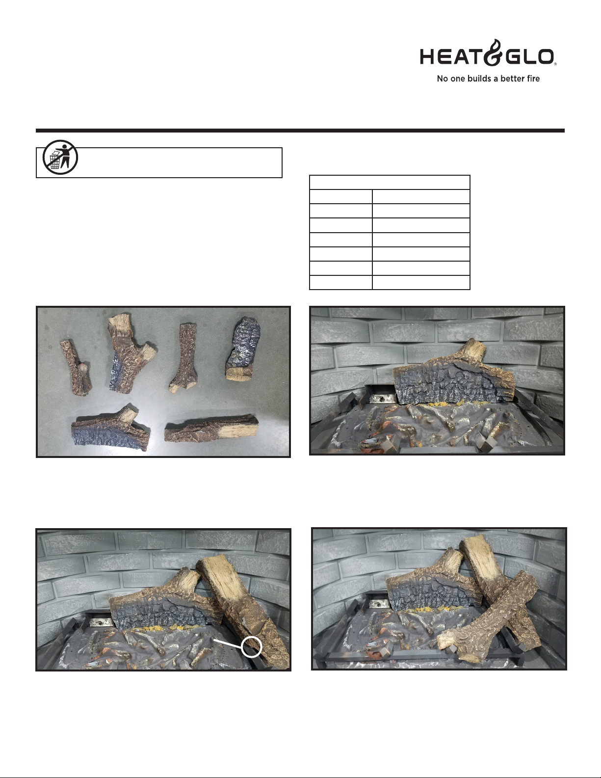
STEP 1. LOG #1 (SRV2106-701): Place the notch on the left underside of log #1, over the log tab that is located on
the right side of the pilot bracket. Move the right end of log #1 forward until it hits the stick on the burner. The closer the log
is to the burner the more glow you will get. Don’t place the log too close to the burner or sooting may occur.
AA
22
33
FORMEDFORMED
GROOVEGROOVE
Figure 3
STEP 2. LOG #2 (SRV2106-703): Fit log #2 on the
top branch of log #1 (A). Rest the formed groove of the lower
part of the log on the grate. It may be necessary to tilt Log
#1 forward to properly engage with Log #2.
Heat & Glo • LOGS-CERONA36 Installation Instructions • 2106-935 Rev. D • 1/21
Figure 4
STEP 3. LOG #3 (SRV2106-705): Place the “Y” portion
of the log in the grate tine and rest the log on the formed
portion of log #2.
1
44
Figure 4 Figure 5
55
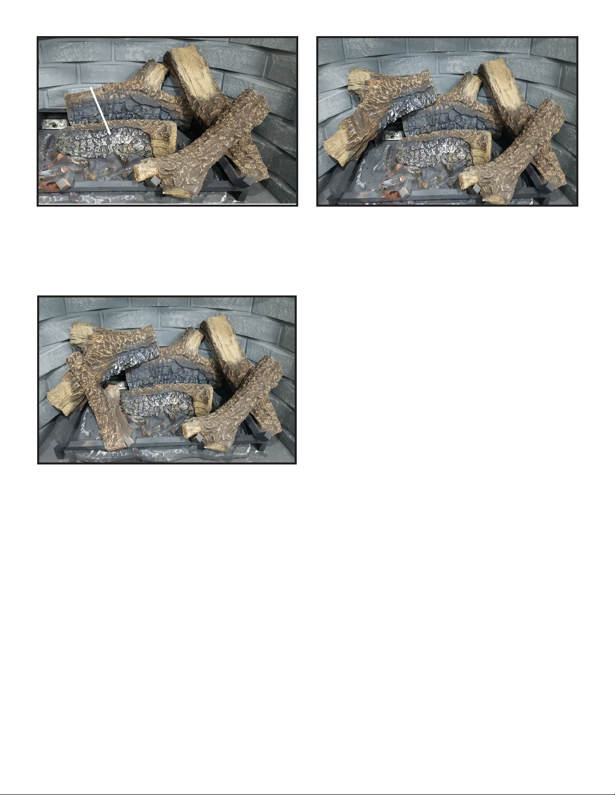
STEP 4. LOG #4 (SRV2106-704): Log #4 is form
tted to the burner. It sits on the middle portion of the
burner as shown.
AA
66
Figure 6
STEP 6. LOG #6 (SRV2106-706): Rest bottom notch
of log #6 on the grate tine and the top part on formed section
of log #5 (A).
STEP 5. LOG #5 (SRV2106-702): Place the right
portion of log #5 on the formed area of log #1. Place the left
side on the grate. Set the notch of the log on the grate.
2
Heat & Glo • LOGS-CERONA36 Installation Instructions • 2106-935 Rev. D • 1/21
 Loading...