

Page 1
OWNERS MANUAL AND
INSTALLATION INSTRUCTIONS
BCBR36
B-VENT GAS APPLIANCE
WARNING: If the information in this manual
is not followed exactly, a fire or explosion may
result causing property damage, personal injury or loss of life.
Do not store or use gasoline or other flammable
vapors and liquids in the vicinity of this or any other
appliance.
What to do if you smell gas
Do not try to light any appliance.
Do not touch any electrical switch; do not use
any phone in your building.
Immediately call your gas supplier from a
neighbors phone. Follow the gas suppliers
instructions.
If you cannot reach your gas supplier, call the
fire department.
Installation and service must be performed by a
qualified installer, service agency or the gas
supplier.
CAUTION:
Do not expose the appliance to
the elements (such as rain, etc.).
WARNING!
Installation and service must be performed by a qualified installer, service agency or the gas supplier. Improper installation,
adjustment, alteration, service or maintenance can cause injury or property damage. Refer to this manual. For assistance or
additional information, consult a qualified installer, service agency or the gas supplier.
06-03 35020 Rev G 1
This manual must be used for installation of the
BCBR36 Gas Appliance and retained by the
homeowner for operation and maintenance
instructions.
Page 2

BCBR36 B-VENT GAS APPLIANCE
Please retain this manual for future use.
TABLE OF CONTENTS
Design and Installation Considerations for B-Vents .................................................................................................... 3
A. Appliance Specifications ............................................................................................................................................... 4
B. Location and Clearances .............................................................................................................................................. 5
C. Framing ......................................................................................................................................................................... 6
D. Setting the Appliance .................................................................................................................................................... 6
E. Venting .......................................................................................................................................................................... 7
F. Utilities ......................................................................................................................................................................... 10
G. Finishing ...................................................................................................................................................................... 14
H. Appliance Preparation ................................................................................................................................................. 14
I. Lighting Instructions .................................................................................................................................................... 16
J. Seasonal Checklist ...................................................................................................................................................... 17
K. Start-up Issues ............................................................................................................................................................ 18
L. Maintenance Instructions ............................................................................................................................................ 19
M. Log Removal/Replacement ......................................................................................................................................... 21
N. Optional Components ................................................................................................................................................. 22
O. Replacement Parts ...................................................................................................................................................... 23
Index ............................................................................................................................................................................ 27
Limited Lifetime Warranty ........................................................................................................................................... 28
WARNING!
DO NOT use this appliance if any part has been under water. Immediately call a qualified service technician to
inspect the appliance and to replace any part of the control system and any gas control which has been under
water.
SAFETY PRECAUTIONS
1. Please read these installation instructions completely before beginning installation procedures. Failure to follow them
could cause an appliance malfunction resulting in serious injury and/or property damage.
2. Installation and repair should be done by a qualified service person. This appliance should also be inspected annually
by a qualified service person. More frequent inspections/cleaning may be required due to excessive lint from carpeting,
bedding materials, etc. It is imperative that the control compartment, burners and circulating air passageways of the
appliance be kept clean.
3. This is a vented decorative gas appliance. Do not burn wood or other material in this appliance.
4. NEVER leave children unattended when there is a fire burning in the appliance.
5. This appliance must be vented with a 5 B-vent system and must terminate above the roof line. Venting must not be
connected to a chimney flue servicing a solid fuel burning appliance.
6. Use only the fuel gas specified on the rating label of this gas appliance.
7. The appliance area shall be kept clear and free from combustible materials, gasoline and other flammable vapors and
liquids.
8. While servicing this appliance, always shut off all electricity and gas to the appliance. This will prevent possible
electrical shock or burns. Also, make sure the appliance is completely cooled before servicing.
9. Do not use this appliance if any part has been under water. Immediately call a qualified service technician to inspect
the appliance and to replace any part of the control system and any gas control which has been under water.
10. Be sure to provide adequate clearances around the air openings into the combustion chamber and adequate
accessibility clearances for servicing and proper operation.
11. Provisions shall be made to provide adequate combustion and ventilation air. The flow of combustion and ventilation
air should not be obstructed.
2 35020 Rev G 06-03
Page 3
BCBR36 B-VENT GAS APPLIANCE
DESIGN AND INSTALLATION CONSIDERATIONS FOR B-VENTS
When selecting a location for your B-Vent appliance, it is important to evaluate a number of considerations. Modern
construction techniques can create conditions that may not allow your vent to draft properly. This may result in spillage
from your B-Vent appliance, as well as cause other combustion appliances to operate incorrectly.
Tightly sealed construction is important for energy efficiency. Unfortunately, a great deal of effort has been directed to
tightening up sidewall construction, while considerably less attention has been paid to tightening upper portions of the
warm air envelope (insulated ceilings). This has increased the Stack Effect, a condition that increases the negative
pressure generated by the structure. This negative pressure will directly affect the drafting performance of a B-Vent
appliance vent. To minimize the negative pressure generated by stack effect, make certain that all ductwork installed in
the attic spaces is sealed airtight. Minimize the number of recessed light fixtures installed in the insulated ceiling and use
sealed recessed light fixtures. Finally, make certain the whole house fans and attic access panels are tightly sealed.
These are important design considerations that must be observed during the design and construction stage of the home.
If you desire to put an appliance in your basement, we recommend that you consider a direct vent gas appliance. Basements
always have a significant negative air pressure that causes the B-Vent system to be more susceptible to spillage and cold
flue backdrafting. Since direct vent gas appliances are sealed, they are not affected by the negative pressure that exists
in basements.
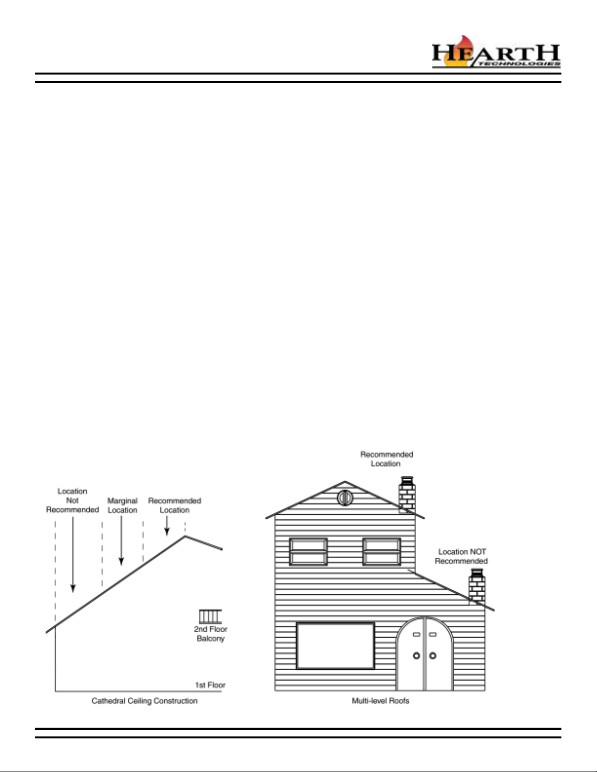
Finally, a B-Vent appliance performs best when the vent (roof termination) is located on the upper half of the roof, especially
when cathedral ceilings are present. Vents that are located on the lower half of the roof realize what is known as lazy flue
and will not draft as well as a vent that is located in the upper portion of the roof. The reason for this is that the stack effect
generated by the overall height of the living spaces inside the house will exceed the draft generated by the vent system.
If you desire to place an appliance in a location where the termination cap would be located on the lower half of a roof;
such as on an outside wall at the base of a cathedral ceiling, we recommend that you consider using a direct vent gas
appliance. This will ensure an appliance that operates correctly.
These properties do not affect just your B-Vent appliance. They can cause any woodburning fireplace as well as any
conventionally vented (B-Vent) gas appliance to operate improperly. Careful planning at this stage of your project will
ensure satisfaction with the operation of your appliance once it is completed.
06-03 35020 Rev G 3
Page 4
BCBR36 B-VENT GAS APPLIANCE
A. APPLIANCE SPECIFICATIONS
U.S. and Canada Certification
The BCBR36 Gas Appliance has been tested in accordance
with the standards ANSI Z21.50-2000 and CSA 2.22-2000,
and has been listed by Underwriters Laboratories Inc. for
installation and operation as described in this manual. All
components are UL, AGA, CGA, or CSA safety certified.
Local Codes
This installation must conform with local codes. In the
absence of local codes comply with the National Fuel Gas
Code ANSI Z223.1-latest edition in the U.S.A., and the
CAN/CGA B149 Installation Codes in Canada.
If you need assistance during installation, please contact
your local dealer or the Technical Services Department,
Hearth & Home Technologies, 1915 W. Saunders Street,
Mt. Pleasant, Iowa 52641, 1-800-843-2848.
We strongly recommend that you DO NOT install BVent Gas Appliances in strong negative air locations,
such as a basement or a public facility. Living rooms
with cathedral ceilings could be susceptible to a
negative air situation, but such installations can be
overcome through raising the termination,
depending on specific installations. This appliance
uses room air for normal operation and could have
problems establishing a positive draft in a negative
air location. In lieu, we recommend a Direct Vent Gas
Appliance.
Note: Minimum and maximum clearances must be main-
tained at all times. Illustrations throughout these instructions reflect typical installations and are for design purposes only. Actual installation may vary slightly due to
individual design preferences.
The illustrations and diagrams used throughout these
installation instructions are not drawn to scale.
Tools and building supplies normally required for
installation:
Saw Wall-finishing materials
Pliers Framing material
Hammer Appliance surround
Phillips screwdriver Caulking material
Tape measure Safety gloves
Plumb line Electric drill/bits
Level Framing Square
BCBR36 Nomenclature
#golataCnoitpircseD
CBeciohCsredliuB
BtneV-B
RtnaidaR
63ecnailppA"63
WARNING!
This appliance is tested and listed for use only with
the optional accessories listed in these instructions. Use of optional accessories not specifically
tested for this appliance could void the warranty
and/or result in a safety hazard.
Typical Installation Components
4 35020 Rev G 06-03
Page 5
BCBR36 B-VENT GAS APPLIANCE
B. LOCATION AND CLEARANCES
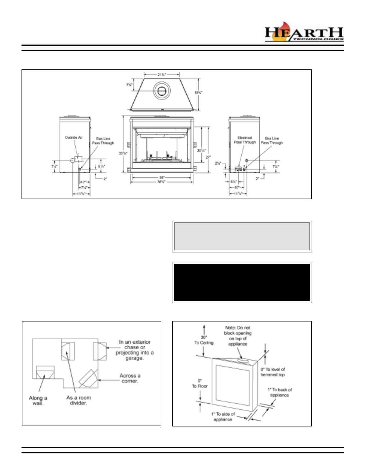
Appliance Dimensions
1. Appliance Locations and Space Requirements
Figure 1 illustrates a variety of ways the appliance may
be located in a room. The BCBR36 may be installed
directly on the floor or raised on a hearth. These
appliances are certified for installation in a bedroom
or bed/sitting room in the U.S. and Canada, provided
that the bedroom or bathroom has a volume of at least
1150 cubic feet.
2. Clearances
Figure 2 shows all clearances that must be maintained
around the appliance.
CAUTION:
Do not expose the appliance to the elements (such
as rain, etc.).
WARNING!
Due to high temperatures, the appliance should be
located out of traffic and away from furniture and
draperies.
Figure 1 - Appliance Locations
Appliance Clearances to Combustible Materials
06-03 35020 Rev G 5
Figure 2
Page 6
BCBR36 B-VENT GAS APPLIANCE
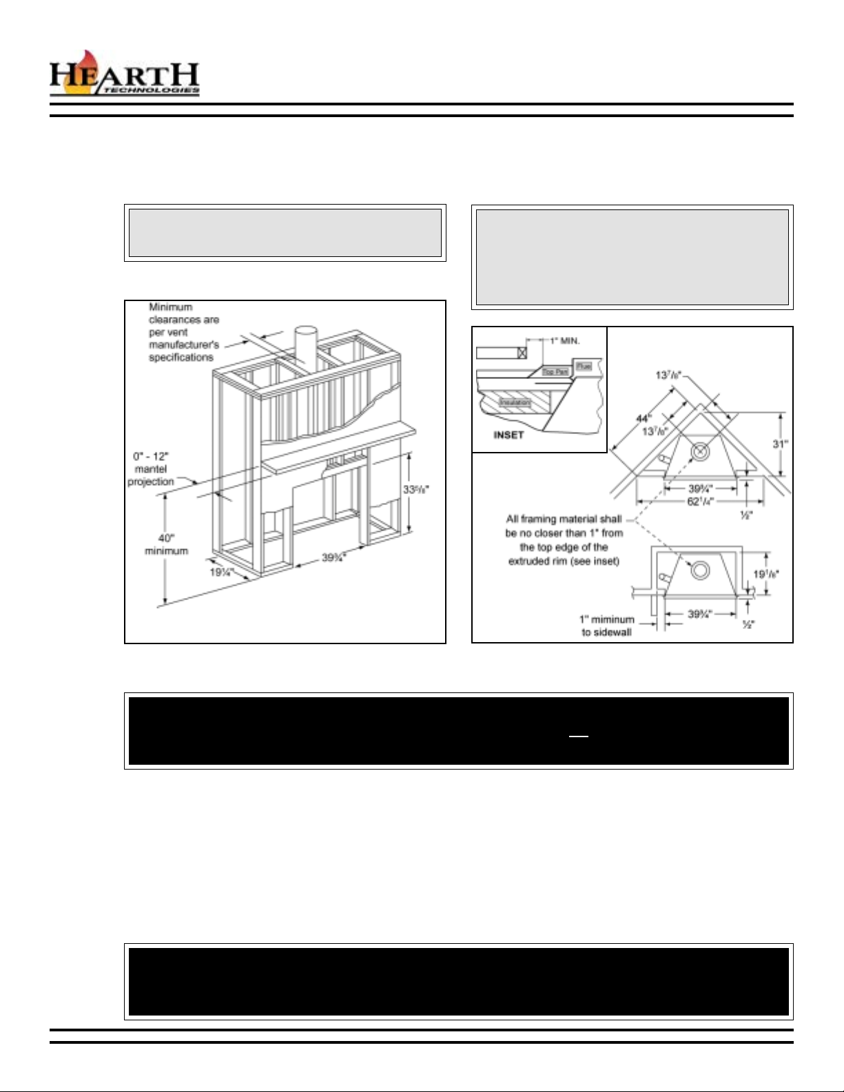
C. FRAMING
Figure 3 shows typical framing of this appliance using combustible materials and the minimum mantel heights. All required
clearances to combustibles must be adhered to. Figure 4 shows rough framing dimensions.
CAUTION:
Wear gloves and safety glasses for protection.
Header and mantel
heights are measured
from the base of the
appliance.
Figure 3 - Framing
CAUTION:
Provide adequate clearances around the air openings into the combustion chamber and adequate
accessibility clearances for servicing and proper
operation.
Figure 4 - Rough Framing Dimensions
WARNING!
To prevent contact with sagging or loose insulation, the appliance must not be installed against vapor barriers or exposed insulation.
D. SETTING THE APPLIANCE
This appliance may be placed on a smooth combustible or noncombustible continuous, flat surface. When the appliance
is installed directly on carpeting, tile, or a combustible material other than wood flooring, the appliance shall be
installed on a metal or wood panel extending the full width and depth of the appliance. Slide the appliance into
position and level the appliance from side-to-side and front-to-back. Shim with noncombustible material as necessary.
Secure the appliance by bending out the nailing flanges on each side of the appliance and nail to framing. The nailing
flanges have been positioned ½ back from the front of the appliance to allow the addition of drywall.
WARNING!
This appliance may only use an approved B-Vent chimney system. It must not be connected to a chimney flue
servicing a separate solid fuel or gas fuel burning appliance.
6 35020 Rev G 06-03
Page 7
BCBR36 B-VENT GAS APPLIANCE
E. VENTING
Note: This appliance requires a 5 B-vent for operation. Never down-size pipe.
1. Clearances
Vent clearances are per vent manufacturers specifications.
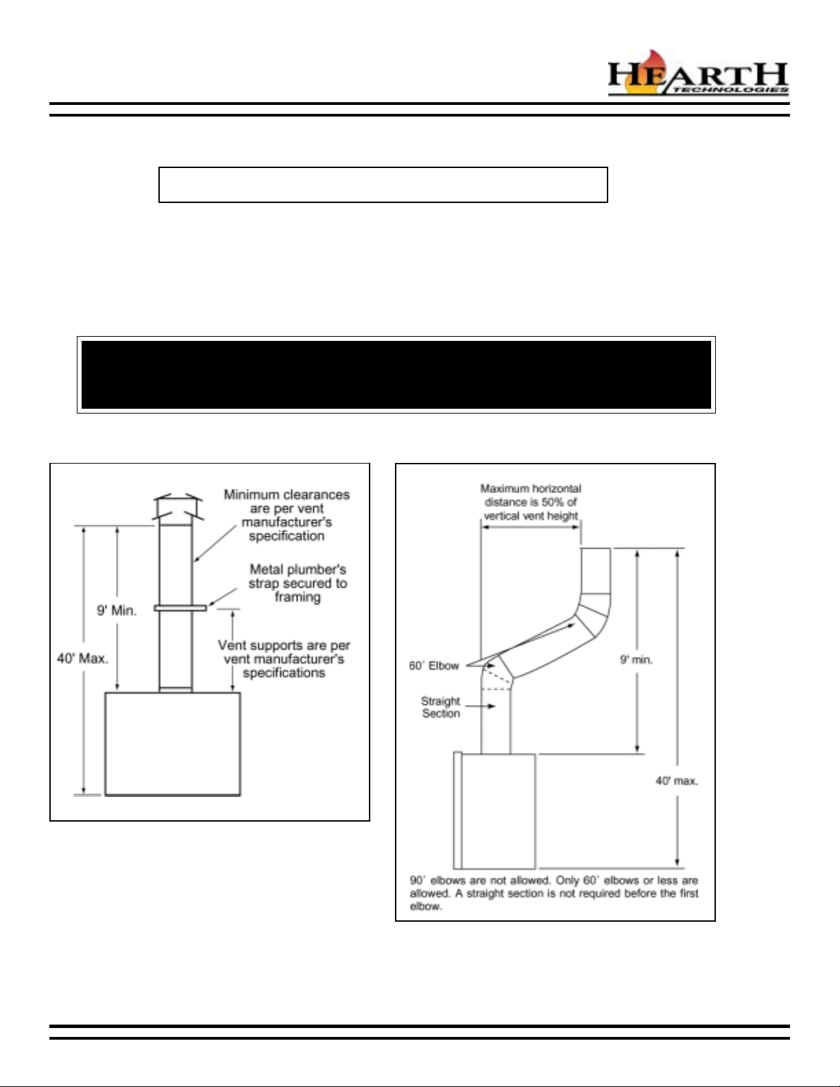
2. Vent Lengths
Various venting configurations are shown in Figures 5 and 6 from which maximum vent runs can be determined.
WARNING - RISK OF FIRE!
Always maintain minimum clearances or greater around the vent system. Do not pack air spaces with
insulation or other material.
Figure 5
Vertical Termination Vent Lengths
Figure 6
Venting off the Top of the Appliance
06-03 35020 Rev G 7
Page 8
BCBR36 B-VENT GAS APPLIANCE
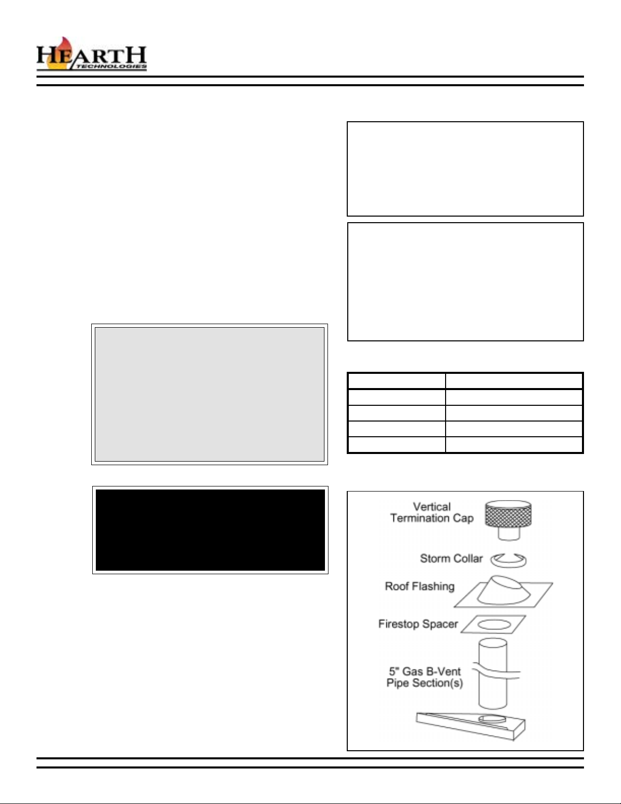
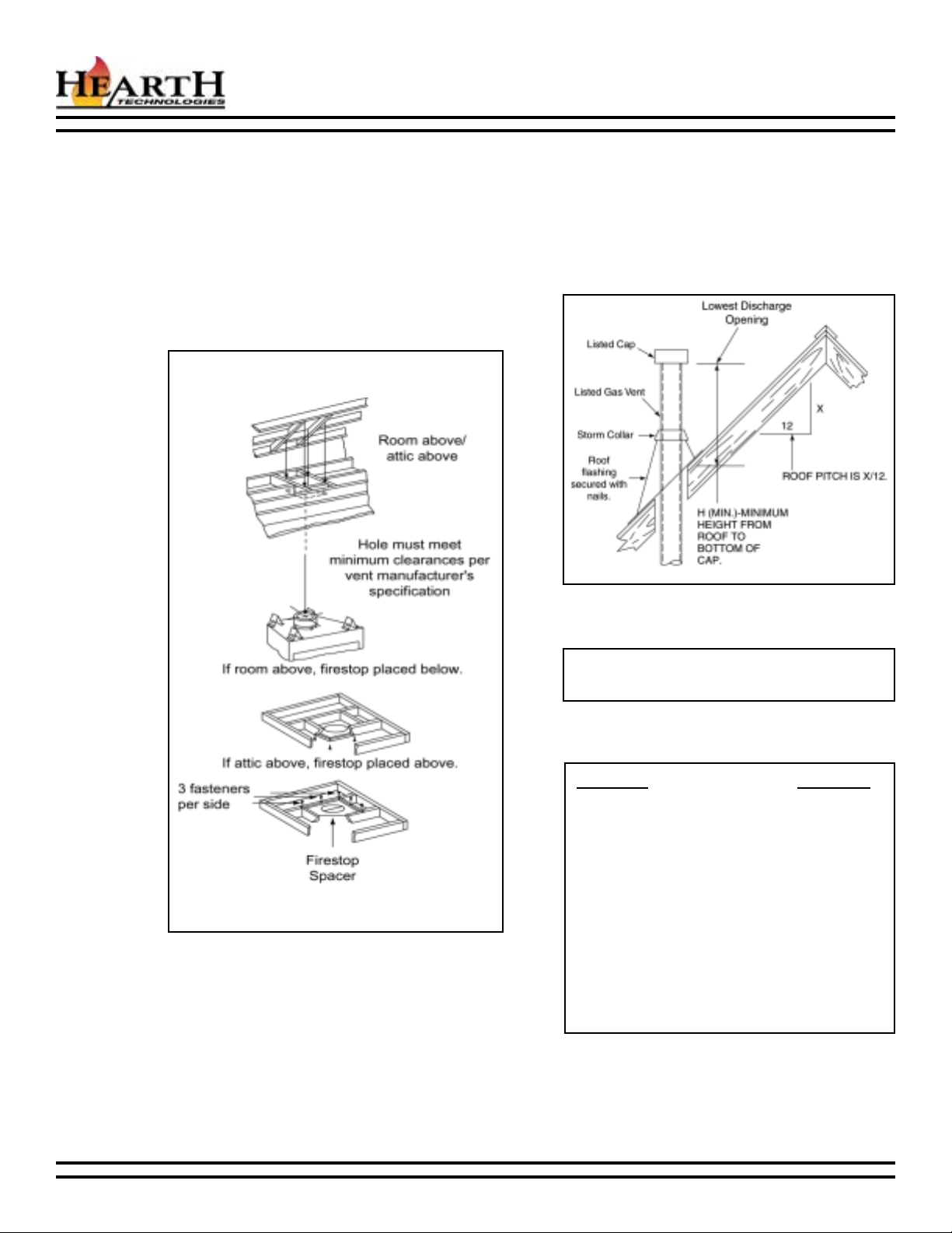
3. Firestop Spacer/Vent Installation
Frame an opening and install a firestop spacer
whenever the vent penetrates a ceiling/floor area, as
shown in Figure 7. Frame the opening with the same
sized lumber as used in the ceiling/floor joists. Unless
the flue is offset, the hole should be directly above the
appliance. DO NOT pack insulation around the vent.
Assemble vent sections as per manufacturers
specifications.
4. Chase/Termination Installation
Figure 8 and Table 1 specify minimum vent heights for
various pitched roofs.
These vent heights are necessary for safety and do
not ensure draft-free operation. Trees, buildings,
adjoining roof lines, adverse conditions, etc. may create
a need for a taller vent should down drafting occur.
Figure 8
Vent Height for Vertical Termination
Figure 7
Installing the Firestop Spacer
Note: To ensure proper operation, verify all venting
and the termination are unobstructed.
Roof Pitch H (Min.) Ft.
Flat to 6/12 ................................................ 1.0
6/12 to 7/12 ............................................... 1.25
Over 7/12 to 8/12 ...................................... 1.5
Over 8/12 to 9/12 ...................................... 2.0
Over 9/12 to 10/12 .................................... 2.5
Over 10/12 to 11/12 .................................. 3.25
Over 11/12 to 12/12 .................................. 4.0
Over 12/12 to 14/12 .................................. 5.0
Over 14/12 to 16/12 .................................. 6.0
Over 16/12 to 18/12 .................................. 7.0
Over 18/12 to 20/12 .................................. 7.5
Over 20/12 to 21/12 .................................. 8.0
Table 1
Vent Height
8 35020 Rev G 06-03
Page 9
BCBR36 B-VENT GAS APPLIANCE
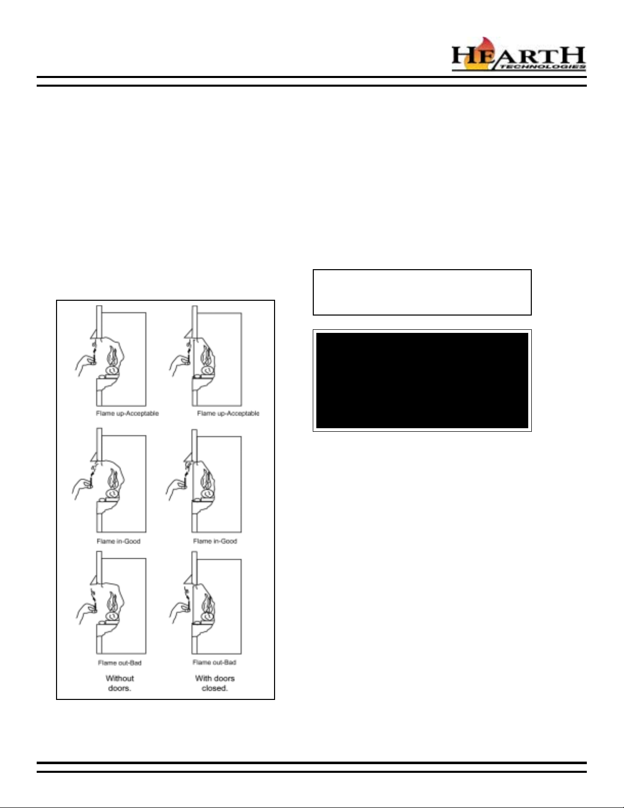
5. Checking the Vent System
Test the venting system periodically to assure proper
operation. This can be done with a match while the
appliance is operating.
Hold a lighted match at the top edge of the appliance
opening. If the flames and smoke remain upright,
ventilation is acceptable. If the flames and smoke are
drawn into the appliance, this means ventilation is
good. If the flames and smoke are forced away from
the appliance, this may indicate a ventilation blockage
or down draft resulting in gas spillage into your home.
If this occurs, turn off the appliance and do not burn it
until it has been inspected by a qualified service
person.
If you have installed optional doors, close the doors
and conduct the test following the same instructions
above. See Figure 9.
6. Outside Air Kit Installation
An outside air kit is available as an optional feature
with this appliance. An outside air kit helps to decrease
the amount of room air taken, by utilizing outside air
for combustion. It is strongly recommended that it be
installed. An outside air kit can be installed only on the
left side.
It is recommended to utilize the shortest duct run to
optimize the performance of the outside air kit. The
outside air kit inlet thimble should be positioned at least
four feet above the ground level, in a manner that will
not allow snow, leaves, etc. to block the inlet.
To install the outside air kit, refer to the installation
instructions provided with the kit.
Note: The outside air kit can terminate at any level
with the exception that it must terminate at least one
foot below the vent termination cap.
WARNING!
Exhaust products of gasoline engines are hazardous. The outside air must not be taken from
a garage space, attic spaces, basements, or
above the roofing where other heating appliances, fans, or chimneys exhaust or utilize air.
Figure 9
Testing Ventilation
06-03 35020 Rev G 9
Page 10

BCBR36 B-VENT GAS APPLIANCE
F. UTILITIES
1. High Altitude Installation
For U.S. installation, appliances are tested and approved for elevations from 0-2000 feet. When installing this appliance
at an elevation above 2000 feet, National Fuel Gas Codes require a decrease of the input rating by changing the
existing burner orifice to a smaller size. Input should be reduced 4% for each 1000 feet above sea level. Check with
the local gas utility for proper orifice size identification. The correct orifice is available from your Hearth & Home
Technologies distributor.
For Canada, appliances are certified for elevations from 0-4500 feet. When installing this appliance at an elevation
between 0-4500 feet in Canada, the input rating does not need to be reduced. When installing this appliance at an
elevation above 4500 feet in Canada, check with local authorities.
2. Gas Line Connection
The appliance is provided with a stainless steel flexible connector and a listed (and Commonwealth of Massachusetts
approved) T-handle manual shutoff valve.
You may plumb this appliance from either the right or left side of the appliance. The incoming gas line should be piped
into the valve compartment and connected to the 1/2 FIP connection provided on the manual shutoff valve. See
Figure 10 to connect the gas line. Optional: Seal around the gas line to prevent cold air leakage.
All connections must be tightened and checked for leaks with a soap and water solution or a leak detector.
Bleed the gas line to extract any air that may have been trapped inside the pipe.
Note: Have the gas supply line installed in accordance with building codes by a qualified installer approved and/or
licensed as required by the locality. In the Commonwealth of Massachusetts, installation must be performed by a
licensed plumber or gas fitter.
Note: This appliance and its manual shutoff valve must be disconnected from the gas supply piping system during any
pressure testing of that system at test pressures in excess of 1/2 psi (3.5 kPa). The appliance must be isolated from the
gas supply piping system by closing its manual shutoff valve during any pressure testing of the gas supply piping
system at test pressures equal to or less than 1/2 psi (3.5 kPa).
Figure 10 - Gas Line
10 35020 Rev G 06-03
Page 11

BCBR36 B-VENT GAS APPLIANCE
WARNING!
This valve has been preset at the factory. Altering
settings may result in fire hazard or bodily injury.
3. Gas Pressure
On the intermittent pilot gas control valve, a pressure tap is included on the front face of the valve. Pressure taps are
immediately upstream of the gas supply connection and accessible for test gauge connection. See Table 2.
4. Gas Conversions
Natural or propane gas conversions necessary to meet the application need to be made by a qualified technician
using Hearth & Home Technologies specified and approved parts.
In the event your appliance must be converted to use propane, you must use a DCKP conversion kit. To be converted
to use natural gas, you must use a DCKN conversion kit.
63RBCB
)GN(erusserPylppuSsaGtelnI.c.w.ni).xam(0.7-).nim(5.4
)GN(sserPdlofinaMlamitpO.c.w.ni5.3
)PL(erusserPylppuSsaGtelnI.c.w.ni).xam(0.41-).nim(0.11
)PL(erusserPdlofnaMmumitpO.c.w.ni01
Table 2
63RBCB
)GN(etaRtupnI.rh/UTB000,32
)PL(etaRtupnI.rh/UTB000,32
)PL(eziSecifirOmm24.1/650.
)GN(eziSecifirOmm62.2/980.
Table 3
06-03 35020 Rev G 11
Page 12

BCBR36 B-VENT GAS APPLIANCE
5. Ignition System
This appliance is equipped with an intermittent pilot control valve which operates on a 3 volt system. See wiring
diagram, Figure 11.
The appliance is supplied with a battery pack and a 3 volt AC transformer, which requires the installation of the
supplied JK9 Junction Box Kit. It is highly recommended that the JK9 be installed at this time to avoid reconstruction.
The battery pack requires two D cell batteries (not included). Batteries cannot be placed in the battery pack while
using the 3 volt AC transformer. Conversely, the transformer must be unplugged if the battery pack is used.
Note: This appliance must be electrically wired and grounded in accordance
with local codes or, in the absence of local codes, with National Electric Code
ANSI/NFPA 70-latest edition or the Canadian Electric Code, CSA C22l.1.
Battery polarity must be correct or control module
damage will occur.
5.
CAUTION:
Figure 11 - Intermittent Pilot Ignition Wiring Diagram
12 35020 Rev G 06-03
Page 13

BCBR36 B-VENT GAS APPLIANCE
6. JK9 Junction Box Installation
Your appliance is supplied with a JK9 Junction Box. To operate the appliance with the supplied 3V AC transformer
and/or remote control option, it is recommended that the junction box be installed and wired at this time to avoid
reconstruction.
a. Refer to installation instructions included with the JK9 Junction Box.
b. Wire the junction box per the diagram in Figure11.
c. Prior to attaching the junction box to the appliance, the heat shield supplied with your appliance must be installed.
Insert the top flange of the heat shield through the electrical knockout hole from the inside (Figure12), then insert
the JK9 through the hole and attach with three screws. See Figure 13.
Figure 12 - Attaching the Heat Shield
Figure 13 - Attaching the Junction Box
06-03 35020 Rev G 13
Page 14

G. FINISHING
1. Combustible Finishing Material
Material made of or surfaced with wood, compressed
paper, plant fibers, plastics, or any material capable
of igniting and burning, whether flame proofed or not,
plastered or unplastered (this includes drywall).
2. Noncombustible Finishing Material
Material which will not ignite and burn. Such materials
are those consisting entirely of steel, iron, brick, tile,
concrete, slate, glass or plasters, or any combination
thereof, or have a UL fire rating of zero (0).
3. High Temperature Sealant Material
Sealants that will withstand high temperatures: General
Electric RTV103 (Black) or equivalent. Rutland, Inc.
Appliance Mortar #63, or equivalent.
A high temperature sealant, 1/8 wide minimum bead,
must be used to close off gaps between the appliance
and facing to prevent cold air leaks. See Figure 14.
A combustible mantel may be installed. Please refer
to Figure 3, page 6.
BCBR36 B-VENT GAS APPLIANCE
Figure 14
WARNING!
Air slots on this appliance cannot, in any way, be
covered as it may create a fire hazard.
H. APPLIANCE PREPARATION
1. Appliance Preparation
The log set should look similar to that in Figure 26, page 21. Remove the control access panel from its shipping location
(Figure 15) by removing the two screws holding it in place. Replace the two screws. Put the control access panel in place
by sliding one end on the appliance bottom by means of slots in the control access panel. Slide the other end onto the
appliance bottom. See Figure 16.
Figure 15 - Control Access Panel Shipping Location
Figure 16 - Control Access Panel Installation/
Removal
14 35020 Rev G 06-03
Page 15

BCBR36 B-VENT GAS APPLIANCE
2. Placing the Lava Rock and Vermiculite
Place lava rock on top of control access panel, in front of, under and around burner. When placing vermiculite,
sprinkle it evenly over the area covered by the lava rock. See Figures 17-18.
It is not necessary to use all the lava rock and vermiculite. Save the remainder for future use.
3. Placing the Rock Wool
Place approximately 1/2 diameter pieces of rock wool under the front log, on the lower portion of the burner tube.
Place the rock wool the full length of the burner. Do not pack the wool tightly against the burner. This appliance is
supplied with one bag of rock wool. It is not necessary to use all the wool. Save the remaining amount for future use.
See Figure 19.
Figure 17
Placing the Lava Rock
Figure 18
Placing the Vermiculite
Figure 19
Placing the Rock Wool
06-03 35020 Rev G 15
Page 16

BCBR36 B-VENT GAS APPLIANCE
I. LIGHTING INSTRUCTIONS
WARNING!
If you do not follow these instructions exactly, a fire or explosion may result causing property damage,
personal injury or loss of life.
A. This appliance is equipped with an ignition device which automatically lights the pilot. Do not try to light the pilot
by hand.
B. BEFORE LIGHTING smell all around the appliance area for gas. Be sure to smell next to the floor because some
gas is heavier than air and will settle on the floor.
WHAT TO DO IF YOU SMELL GAS:
Do not try to light any appliance.
Do not touch any electric switch; do not use any phone in your building.
Immediately call your gas supplier from a neighbors phone. Follow the suppliers instructions.
If you cannot reach your gas supplier, call the fire department.
C. Use only your hand to close the gas line. Never use tools. If the knob will not push in or turn by hand, dont try to
repair it; call a qualified service technician. Force or attempted repair may result in a fire or explosion.
D. Do not use this appliance if any part has been under water. Immediately call a qualified service technician to
inspect the appliance and to replace any part of the control system and any gas control which as been under
water.
INTERMITTENT PILOT IGNITION LIGHTING INSTRUCTIONS
1. Turn wall switch to the OFF position.
2. This appliance is equipped with an ignition device which automatically lights the pilot. Do not try to light the pilot
by hand.
3. Wait five minutes to clear out any gas. If you then smell gas, STOP! Follow B in the safety information above on
this label. If you do not smell gas, go on to the next step.
4. Turn the wall switch to the ON position.
5. If the appliance will not operate, follow the instructions TO TURN OFF THE GAS TO THE APPLIANCE and call
your service technician or gas supplier.
6. If using the battery pack and the appliance will not operate, check the batteries for sufficient charge and replace
if necessary.
TO TURN OFF THE GAS TO THE APPLIANCE
1. Turn off the wall switch.
2. Open control access panel. Turn manual shutoff
valve to the CLOSED position. Do NOT force.
3. Close control access panel.
16 35020 Rev G 06-03
Page 17

BCBR36 B-VENT GAS APPLIANCE
J. SEASONAL CHECKLIST
WARNING!
Children and adults should be alerted to the hazards of high surface temperatures and should stay away to
avoid burns or clothing ignition. Young children should be carefully supervised when they are in the same
room as the appliance.
CAUTION:
Any safety screen or guard removed for servicing an appliance must be replaced prior to operating this
appliance.
Clothing or other flammable material should not be placed on or near the appliance.
Installation and repair should be done by a qualified service person. The appliance should be inspected
before use and at least annually by a qualified service person. More frequent cleaning may be required
due to excessive lint from carpeting, bedding material, etc. It is imperative that control compartments,
burners and circulating air passageways of the appliance be kept clean.
Before operating this appliance, have a qualified technician:
1. Review proper placement of logs, rock wool and vermiculite (pages 15 and 21).
2. Check wiring (page 12).
3. Check air shutter adjustment (page 19).
4. Ensure there are no gas leaks (page 10).
5. Ensure the flow of combustion and ventilation air is not obstructed.
WARNING!
Keep the area near the appliance clear and free from combustible materials, gasoline and other flammable vapors and liquids.
06-03 35020 Rev G 17
Page 18

BCBR36 B-VENT GAS APPLIANCE
1. Intermittent Pilot ignition Operation
a. Lighting the Appliance During Regular Use
Turn the wall switch to ON.
b. Shutdown During Regular Use
Turn the wall switch to OFF.
c. To Shut Down the Appliance for a Long Period
of Time
Turn all wall switches to OFF.
Turn the gas line to CLOSED.
d. To relight the appliance, see page 16.
2. Fuel Conversion Instructions
a. Do not burn wood or other material in this
appliance.
b. Natural or propane gas conversions necessary to
meet the application need to be made by a
qualified technician using Hearth & Home
Technologies specified and approved parts.
c. In the event you must convert your appliance to
propane, refer to Section F, #4. Gas Conversions
(page 11).
3. Operating the Outside Air Kit
The outside air kit is supplied as an optional feature
with this appliance. The outside air kit helps decrease
the amount of room air taken by utilizing outside air for
combustion. It is strongly recommended that it be
installed.
To operate the outside air kit, before starting the
appliance: Grasp the small, black handle located on
the left side of the appliance. See Figure 20. Lift the
handle and move it to the left. When through burning
the appliance, grasp the handle and move it to the right
to close the outside air door.
CAUTION:
The air kit handle may get hot while burning the
appliance. Use care when operating the handle.
WARNING!
Do not use this appliance if any part has been under water. Immediately call a qualified service technician to inspect the appliance and to replace any
part of the control system and any gas control which
has been under water.
K. START-UP ISSUES
EUSSISNOITULOS
.1ehtnonoitasnednoC
sroodssalg
.2semalfeulB.2otnigeblliwsemalfehtdnanoitarepolamronfotluserasisihT
.3ecnailppaehtmorfrodO.3ehtrofrodonaesaeleryamecnailppasiht,detarepotsrifnehW
.4ehtnomliF
sroodssalg
.1sA.snoitairaverutarepmetdnanoitsubmocsagfotluserasisihT
.4.sgoldnatniapehtfossecorpgnirucehtfotluserlamronasisihT
Figure 20 - Operating the Outside Air Kit and
Circulating Air Passageway
.raepasiddluohsnoitasnednocsiht,smrawecnailppaeht
.nrubotdewollasiecnailppaehtsawolley
dnatniapehtfognirucehtybdesuacsisihT.sruohlarevestsrif
.gnirutcafunammorfgniniamerslioynafoffogninrubeht
gninrublaitinifosruoh6-4nihtiwdenaelcebdluohssroodssalG
A.ssecorpgnirutcafunamehtmorfslioybtfelstisopedevomerot
.yrassecenebyamossarBsahcusrenaelcevisarba-non
WARNING!
Never use gasoline, gasoline-type lantern fuel, kerosene, charcoal lighter fluid or similar liquids in
this appliance. Keep any flammable liquids a safe distance from the appliance.
18 35020 Rev G 06-03
Page 19

BCBR36 B-VENT GAS APPLIANCE
L. MAINTENANCE INSTRUCTIONS
1. Cleaning the Burner and Control Compartment
Keep the burner and control compartment clean by
brushing and vacuuming at least once a year. Always
turn off the wall switch (or remote control) and gas valve
before cleaning.
2. Checking the Vent System
Inspect the flame of the burner periodically, making
sure the flames are steady, not lifting or floating. The
flame color should be blue with yellow tips. The sensor
tip should be covered with flame. See Figure 21.
If the vent configuration is installed incorrectly, the vent
may cause the flames inside the appliance to lift or
ghost, a dangerous situation. Inspect the flames after
installation to ensure proper performance. See
Figure22. If the vent configuration is correct, yet the
flames are lifting or ghosting, shut off gas to the
appliance and contact a qualified service technician.
Air Shutter Adjustment
To reduce the possibility of soot, we have equipped
your appliance with an adjustable air shutter. See
Figure 23. Your air shutter is provided in the closed
position for natural gas and 1/8 open for propane.
Figure 21 - Intermittent Pilot Ignition Assembly
Note: The look of the flames and embers may differ
based on the type of fuel and venting assembly that
is required.
3. Proper Operation of Optional Glass Doors
While operating your appliance, you should either have
the doors completely open or completely closed, but
never partially open. See Figure 24.
Figure 22 - Flame Patterns
Figure 23 - Air Shutter
Figure 24 - Correct Operation of Doors
06-03 35020 Rev G 19
Page 20

4. High Limit Safety Switch
This appliance is equipped with an auto reset high limit
switch which will shut down the appliance if it becomes
too hot. If this happens, turn the appliance off and shut
off the gas supply. Do not attempt to operate the
appliance until it has been examined by a qualified
service technician. See Figure 25 for limit switch
location.
5. Glass Breakage/Cleaning
It is recommended to wear gloves while handling or
removing glass. DO NOT REMOVE GLASS WHEN
IT IS HOT!
a. Clean glass after initial 4-6 hours burning time.
This is to remove any film that develops from oils
and log burn. After initial cleaning, clean as
needed.
b. Handle glass panel with care to avoid striking or
scratching it on hard objects.
c. To clean the glass, use a nonabrasive, mild
cleaning solution (i.e. Brasso). Apply an adequate
amount to the glass and wipe off per
manufacturers instructions. Contact your local
stove shop or fireplace accessories store for
further recommendations.
d. In the event of glass breakage, carefully remove
the glass frame. This will allow the removal of all
glass fragments and sheet metal edge protection
strips. Vacuum all remaining glass pieces with a
shop vac. DO NOT VACUUM IF PIECES ARE
HOT! Replace glass doors only with a Hearth &
Home Technologies glass door assembly ordered
through your local distributor/dealer. Never use
substitute material. Only fully tempered soda lime
safety glass may be used on this appliance.
BCBR36 B-VENT GAS APPLIANCE
WARNING!
Gas appliances equipped with doors should be operated only with doors fully open or doors fully
closed. If doors are left partially open, gas and flame
may be drawn out of the firebox opening, creating
risks of both fire and spillage.
Figure 25 - Limit Switch Location
Note: When cleaning the glass, NEVER use
abrasive materials. NEVER clean glass when it
is hot. Keep pets and children a safe distance
away.
20 35020 Rev G 06-03
Page 21

BCBR36 B-VENT GAS APPLIANCE
M. LOG REMOVAL/REPLACEMENT
1. Remove the lava rock from the appliance and save.
2. The top log is simply placed and located by indents in
the front log.
3. For removal of the front grate/log assembly remove
two screws (one per side) from the hearth pan. Pull
the grate/log assembly forward. See Figure26. Pull
forward on the assembly to remove it from the
appliance and set it aside, being careful not to damage
any of the logs. See Figure 27.
4. To remove the back log, remove two screws and
carefully lift off. See Figure 28.
5. Reverse the order to reinstall the logs.
Figure 26
Unscrewing the Log/Grate Assembly
from the Hearth Pan
Figure 27
Log Removal
06-03 35020 Rev G 21
Figure 28
Back Log Removal
Page 22

AK22 - Air Kit
BCBR36 B-VENT GAS APPLIANCE
N. OPTIONAL COMPONENTS
RC-SMART-HTL
Remote Control
RC-BATT-HTL
Battery-Operated Remote
Control
(Standing Pilot)
RCT-MLT-HTL
Multi-Function
Remove Control
SMART-STAT-HTL
Remote Control with
Thermostat Control
SMART-BATT-HTL
Battery-Operated Remote
Control
with Thermostat Control
DCKN Propane to
Natural Gas
Conversion Kit
DM1036
DM1036B
DM1036S
Bifold Doors
DCKP Natural to
Propane Gas
Conversion Kit
WSK-21
Wall Switch Kit
WSK-21-W
Wall Switch Kit (White)
BCRK36
Refractory
22 35020 Rev G 06-03
Page 23

BCBR36 B-VENT GAS APPLIANCE
O. REPLACEMENT PARTS
Replacement parts are available from your distributor/dealer.
Gas Log Assembly
Valve Assembly
METI#TRAPNOITPIRCSED.YTQ
164943goLtnorF1
284943goLpoT1
374943goLkcaB1
33341looWkcoR1
11982kcoRavaL1
64782etilucimreV1
456843ylbmessAetarG1
564041GN980.ecifirO1
54831PL650.ecifirO1
681241pilCdroC1
762341xelF-09rotcennoCssarB1
869651eniLsaGxelF"011
979651evlaVffO/nO1
0142571woblEssarB1
1108491epaTcitengaM1
2119432paCtsuD1
3161843hctiwStimiL1
4159333etalPevlaV1
51295-395lortnoCnoitingI1
61A495-395kcaPyrettaB1
71500-1204saGlarutaN-.yssAtoliPMI1
600-1204PL-.yssAtoliPMI1
A095-395ssenraHeriW1
81A395-395gulProtpadAV31
91005-395saGlarutaN-evlaV1
105-395PL-evlaV1
0223043ebuTrenruB1
1296843MF06ULB1H.yssAeriW1
2273943MF06KLB1H.yssAeriW1
20682hctiwSllaW.yssAeriW1
Visit our Website at
06-03 35020 Rev G 23
www.fireplaces.com for a dealer/distributor near you!
Page 24

BCBR36 B-VENT GAS APPLIANCE
HOMEOWNERS NOTES
24 35020 Rev G 06-03
Page 25

BCBR36 B-VENT GAS APPLIANCE
HOMEOWNERS NOTES
06-03 35020 Rev G 25
Page 26

BCBR36 B-VENT GAS APPLIANCE
HOMEOWNERS NOTES
26 35020 Rev G 06-03
Page 27

BCBR36 B-VENT GAS APPLIANCE
Index
A
Air Kit 22
Installation 9
Operation 18
Air Shutter 19
Air Shutter Adjustment 19
Appliance Preparation 14
B
Bifold Doors 22
BTUs 11
Building Codes 4
C
Certification 4
Chase Installation 8
Checklist 17
Cleaning
Burner & Control Compartment
19
Clearances 4, 5, 6, 7
Codes 4
Building 4
Electric 12
Gas 4
Combustible Finishing Material 14
Combustible Material 6
Conversion Kits 11, 22
E
Electric Codes 12
F
Finishing 14
Firestop Spacer 8
Flame
Patterns 19
Flames
Blue 18
Framing 6, 8
Fuel Conversion Instructions
11, 18
G
Gas Codes 4
Gas Conversions 11, 18
Gas Line Connection 10
Gas Pressure 11
Glass
Cleaning 20
Condensation 18
Film 18
Glass Doors 19
H
Heat Shield 13
High Altitude Installation 10
High Limit Safety Switch 20
High Surface Temperatures 17
I
Input Rate 11
Inspection 17
Insulation 7, 8
Intermittent Pilot Ignition 19
Operation 18
J
Junction Box 13
L
Lava Rock 15
Lighting Instructions 16
Location and Clearances 5
Log/Grate Assembly 21, 23
Logs
Removal/Replacement 21
M
Maintenance 19
Mantel 14
Minimum Heights 6
N
Nailing Flanges 6
Natural Gas 18
O
Odor 18
Outside Air Kit 22
Installation 9
Operation 18
P
Propane Gas 18
R
Refractory 22
Remote Control 22
Rock Wool 15
S
Sealant Material 14
Space Requirements 5
Start-up Issues 18
T
Termination Installation 8
Testing
Vent System 9
Typical Installation 4
U
Utilities 10
V
Vent Lengths 7
Vent System
Checking 19
Vermiculite 15
Vertical Termination 8
W
Water 18
Website 23
Wiring Diagram 12
06-03 35020 Rev G 27
Page 28

Gas Appliance (Fireplace)
LimiLifetime Warranty
HEARTH & HOME TECHNOLOGIES INC. (HHT) extends the following warranty for Hearth Technologies Inc. gas appliances installed in the United States of America or Canada (the Appliance). Dealers and employees of HHT have no authority
to make any warranty or authorize any remedies in addition to or inconsistent with the terms of this warranty.
Limited Lifetime Warranty
HHT warrants the Appliance for component failure due to a manufacturing defect of any of the following components: combustion chamber, burner pan, and logs. The Limited Lifetime Warranty specified above is subject to the conditions, exclusions and
limitations listed below, is for the period the Appliance is owned by the original homeowner only, and is nontransferable.
1 Year Limited Warranty
HHT warrants the Appliance to be free from failure of any of the following components for a period of one year after installation: valve, flexible gas line connector, glass panel, fan, direct vent chimney components, factory paint, gasket, piezo ignitor,
thermopile, thermocouple, junction box, pilot assembly, shutoff valve, high limit switch, refractory liners, transformer, and
control box. If the HHT Appliance is found to be defective in either material or workmanship within one year of the date of
original installation, HHT will provide replacement parts at no charge and pay reasonable labor and freight costs, and is for the
period of one year following the date of original installation of the Appliance.
Conditions, Exclusions, & Limitations of Liability
A. Both the Limited Lifetime and 1 Year Limited Warranties supplied by HHT apply only while the Appliance is in its location
of original installation. HHTs obligation under this warranty does not extend to damages resulting from (1) installation,
operation or maintenance of the Appliance not in accordance with the Installation Instructions, Operating Instructions, and
the Listing Agent Identification Label furnished with the Appliance; (2) installation which does not comply with local
building codes; (3) shipping, improper handling, improper operation, abuse, misuse, accident or unworkmanlike repairs;
(4) environmental conditions, inadequate ventilation or drafting caused by tight sealing construction of the structure, air
handling devices such as exhaust fans or forced air furnaces, or other causes; (5) use of fuels other than those specified
in the Operating Instructions; (6) installation or use of components not supplied with the Appliance or any other components not expressly authorized and approved by HHT; and/or (7) modification of the Appliance not expressly authorized
and approved by HHT in writing. This warranty is limited to only the component parts manufactured or supplied by HHT.
B. HHTs liability under both the Limited Lifetime Warranty and the 1 Year Limited Warranty is limited to the replacement and
repair of defective components or workmanship during the applicable period. HHT may fully discharge all of its obligations under such warranties by repairing the defective component(s) or at HHTs discretion, providing replacement parts
at no charge and paying reasonable labor and freight costs.
C. EXCEPT TO THE EXTENT PROVIDED BY LAW, HHT MAKES NO EXPRESS WARRANTIES OTHER THAN THE
WARRANTY SPECIFIED HEREIN. THE DURATION OF ANY IMPLIED WARRANTY IS LIMITED TO DURATION OF
THE WARRANTY SPECIFIED ABOVE.
D. Some states do not allow exclusions or limitations of incidental or consequential damages, so those limitations may not
apply to you. This warranty gives you specific rights; you may also have other rights which vary from state to state.
How to Obtain Service
To obtain service under this warranty you must:
1. Send written notice of the claimed condition to the Technical Service Department, Hearth & Home Technologies, 1915 W.
Saunders Street, Mt. Pleasant, Iowa 52641-1563. You may also register your claim online at www.heatilator.com/
contact.asp.
2. Provide proof of purchase, model number, serial number, and manufacturing date code to HHT.
3. Provide HHT reasonable opportunity to investigate the claim, including reasonable opportunity to inspect the Appliance
prior to any repair or replacement work and before the Appliance or any component of the Appliance has been removed
from the place of original installation.
4. Obtain HHTs consent to any warranty work before the work is done.
Additional Information:. If you would like information on current HHT products or want to locate a dealer in your area, call
1-800-843-2848.
28 35020 Rev G 06-03
 Loading...