

Page 1
Underwriters Laboratories Listed
Homologué Underwriters Laboratories
Installers Guide
Guide dinstallation
Model/Modèle:
AT-ZC-B
WARNING: If the information in these
instructions is not followed exactly, a
fire or explosion may result causing
property damage, personal injury or
death.
- Do not store or use gasoline or other
flammable vapors and liquids in the vicinity of this or any other appliance.
- WHA T TO DO IF YOU SMELL GAS:
• Do not try to light any appliance.
• Do not touch any electrical switch.
• Do not use any phone in your
building.
• Immediately call your gas supplier
from a neighbor's phone. Follow the
gas supplier's instructions.
• If you cannot reach your gas supplier , call the fire department.
- Installation and service must be
performed by a qualified installer,
service agency , or the gas supplier .
AVERTISSEMENT: Si ces instructions
ne sont pas suivies à la lettre, un
incendie ou une explosion pourraient en
résulter, causant des dommages
matériels, des blessures ou la mort.
Nentreposez ou nutilisez jamais
dessence ou autres vapeurs et liquides
inflammables à proximité de cet appareil
ou de tout autre appareil.
QUE FAIRE SI VOUS SENTEZ UNE
ODEUR DE GAZ:
Ne tentez dallumer aucun appareil.
Ne touchez aucun interrupteur
électrique.
Nutilisez aucun téléphone dans votre
édifice.
Appelez immédiatement votre
fournisseur de gaz vous servant du
téléphone dun voisin. Suivez les instructions du fournisseur de gaz.
Si vous ne pouvez pas atteindre votre
fournisseur de gaz, appelez le service
des incendies.
Linstallation et lentretien doivent être
effectués par un installateur qualifié, une
agence de maintenance ou le four-
nisseur de gaz.
1. This appliance may be installed in an aftermarket, permanently located, manufactured
(mobile) home, where not prohibited by local
codes.
2. This appliance is only for use with the type of
gas indicated on the rating plate. This appliance is not convertible for use with other
gases, unless a certified kit is used.
1. Cet appareil peut être installé dans un mobile
home préfabriqué, qui a été vendu et ne sera
plus déplacé, si les codes locaux lautorisent.
2. Cet appareil est conçu pour être utilisé
seulement avec le type de gaz indiqué sur la
plaque signalétique. Cet appareil ne peut être
converti à lutilisation dautres gaz quavec un
module homologué.
1
485-981EFB 9/01
Page 2
WARNING: Improper installation, adjustment, alteration, service or maintenance can cause injury or property
damage. Refer to this manual.
For assistance or additional information consult a qualified installer, service
agency or the gas supplier.
Read this manual before installing or
operating this appliance. This Installers
Guide must be left with appliance for
future reference.
AVERTISSEMENT: Une installation, un
réglage, une modification, une
réparation ou un service incorrects
risquent dentraîner des blessures ou
des dommages matériels. Consultez ce
manuel.
Pour obtenir de laide ou des informations supplémentaires, consultez un
installateur qualifié, une agence de
maintenance ou le fournisseur de gaz.
Lisez ce manuel avant dinstaller ou
dutiliser cet appareil. Ce Guide
dinstallation doit rester avec lappareil
pour référence ultérieure.
!
INFORMATION
!
!
!
!
!
!
SAFETY AND WARNING
READ and UNDERSTAND all instructions
carefully before starting the installation. FAILURE
TO FOLLOW these installation instructions may
result in a possible fire hazard and will void the
warranty.
Prior to the first firing of the fireplace, READ the
Using Your Fireplace section of the Owners Guide.
DO NOT USE this appliance if any part has been
under water. Immediately CALL a qualified
service technician to inspect the unit and to
replace any part of the control system and any
gas control which has been under water.
THIS UNIT IS NOT FOR USE WITH SOLID FUEL.
Installation and repair should be PERFORMED
by a qualified service person. The appliance and
venting system should be INSPECTED before
initial use and at least annually by a professional
service person. More frequent cleaning may be
required due to excessive lint from carpeting,
bedding material, etc. It is IMPERATIVE that the
units control compartment, burners, and
circulating air passageways BE KEPT CLEAN
to provide for adequate combustion and ventilation
air.
Always KEEP the appliance clear and free from
combustible materials, gasoline, and other
flammable vapors and liquids.
CONSIGNES DE SÉCURITÉ ET
!
MISES EN GARDE
LISEZ ATTENTIVEMENT toutes les instructions
!
avant de commencer linstallation. Si ces
instructions dinstallation ne sont pas suivies, un
risque dincendie pourrait en résulter et la garantie
sera annulée.
Avant lallumage initial, LISEZ la section du Guide
!
de lutilisateur intitulée Utilisation de votre foyer.
NUTILISEZ PAS cet appareil si une pièce a été
!
submergée. APPELEZ immédiatement un
technicien de service qualifié pour linspection de
lappareil et le remplacement de toute pièce qui
fut submergée.
CET APPAREIL NEST PAS CONÇU POUR
!
ÊTRE UTILISÉ AVEC DES COMBUSTIBLES
SOLIDES.
Linstallation et les réparations doivent être
!
EFFECTUÉES par un technicien de service
qualifié. Lappareil et le système dévacuation
doivent être INSPECTÉS avant la première
utilisation et au moins une fois lan par un
technicien professionnel. Un nettoyage plus
fréquent peut savérer nécessaire en cas
daccumulation de fibres de tapis, de literie, etc.
Il est IMPÉRATIF que le boîtier de commandes,
les brûleurs et les conduits dair de circulation de
lappareil RESTENT PROPRES afin de permettre
une circulation suffisante dair de combustion et
de ventilation.
Ne PLACEZ jamais de matériaux combustibles,
!
essence ou autres vapeurs ou liquides
inflammables à proximité de lappareil.
2
Page 3
NEVER OBSTRUCT the flow of combustion and
!
ventilation air. Keep the front of the appliance
CLEAR of all obstacles and materials for servicing
and proper operations.
N’OBSTRUEZ JAMAIS
!
combustion et de ventilation. Maintenez l’avant de
l’appareil
d’en permettre le service et le bon fonctionnement.
DÉGAGÉ
de tout obstacle et matériau afin
la circulation d’air de
Due to the high temperature, the appliance should
!
be LOCATED out of traffic areas and away from
furniture and draperies. Clothing or flammable
material SHOULD NOT BE PLACED on or near
the appliance.
Children and adults should be ALERTED to the
!
hazards of high surface temperature and should
STAY AWAY to avoid burns or clothing ignition.
Young children should be CAREFULLY
SUPERVISED when they are in the same room as
the appliance.
These units MUST use one of the vent systems
!
described in the Installing the Insert section of the
Installers Guide. NO OTHER vent systems or
components MAY BE USED.
This gas fireplace and vent assembly MUST be
!
vented directly to the outside and MUST NEVER
be attached to a chimney serving a separate solid
fuel burning appliance. Each gas appliance MUST
USE a separate vent system. Common vent
systems are PROHIBITED.
INSPECT the external vent cap on a regular basis
!
to make sure that no debris is interfering with the
air flow.
The glass door assembly MUST be in place and
!
sealed, and the trim door assembly MUST be in
place on the fireplace before the unit can be placed
into safe operation.
DO NOT OPERATE this appliance with the glass
!
door removed, cracked, or broken. Replacement
of the glass door should be performed by a
licensed or qualified service person. DO NOT strike
or slam the glass door.
The glass door assembly SHALL ONLY be
!
replaced as a complete unit, as supplied by the
gas fireplace manufacturer. NO SUBSTITUTE
material may be used.
DO NOT USE abrasive cleaners on the glass door
!
assembly. DO NOT ATTEMPT to clean the glass
door when it is hot.
Turn off the gas before servicing this appliance. It
!
is recommended that a qualified service technician
perform an appliance check-up at the beginning of
each heating season.
Any safety screen or guard removed for servicing
!
must be replaced before operating this appliance.
DO NOT place furniture or any other combustible
!
household objects within 36 inches of the fireplace front.
En raison de la température élevée, l’appareil doit
!
SE TROUVER
à bonne distance des meubles et des rideaux.
PLACEZ JAMAIS DE
inflammables sur l’appareil ou à proximité.
Les enfants et les adultes doivent être AVERTIS
!
des risques que présentent les surfaces à haute
température et doivent RESTER À L’ÉCART afin
d’éviter les brûlures et l’enflammement de
vêtements. Les enfants en bas âge doivent être
SURVEILLÉS ATTENTIVEMENT lorsqu’ils se
trouvent dans la même pièce que l’appareil.
Ces appareils
!
d’évacuation décrits dans la section intitulée
Installation de la cassette dans le
d’installation. AUCUN AUTRE
d’évacuation
Cet appareil à gaz et ce système d’évacuation
!
DOIVENT
directement à l’extérieur et
être raccordés à une cheminée desservant un autre
appareil à combustible solide. Chaque appareil à gaz
DOIT UTILISER
L’utilisation de systèmes d’évacuation en commun
est
INTERDITE
INSPECTEZ
!
ation extérieur afin de vous assurer que la circulation
de l’air ne soit pas entravée par des débris.
La porte en verre
!
tiquement fermée, et l’ensemble de la porte de
garniture
l’appareil puisse fonctionner en toute sécurité.
NE FAITES P AS FONCTIONNER
!
porte en verre est démontée, fêlée ou brisée. La
porte en verre doit être changée par un technicien
de service agréé ou qualifié.
claquez
La porte en verre
!
en tant qu’unité complète, telle qu’elle est fournie
par le fabricant du foyer à gaz.
SUBSTITUTION
N’UTILISEZ PAS
!
sur la porte en verre.
la porte en verre lorsqu’elle est chaude.
Fermez le gaz avant d’effectuer le service de cet
!
appareil. Il est conseillé qu’un technicien de service
qualifié inspecte l’appareil au début de chaque saison
de chauffage.
T ous les écrans et dispositifs de protection démontés
!
pour le service doivent être remis en place avant
l’utilisation de cet appareil.
en dehors des zones de passage et
vêtements OU matériaux
DOIVENT
NE PEUT ÊTRE UTILISÉ
évacuer les gaz de combustion
utiliser l’un des systèmes
système ou élément
.
NE DOIVENT JAMAIS
un système d’évacuation distinct.
.
régulièrement le capuchon d’évacu-
DOIT
être en place et hermé-
DOIT
être en place sur le foyer pour que
cet appareil si la
NE
frappez et
PA S
la porte en verre.
DOIT
être changée
ne peut être utilisé.
de produits d’entretien abrasifs
N’ESSA YEZ PAS
UNIQUEMENT
AUCUN
matériau
de nettoyer
NE
Guide
NE
DE
NE placez NI meubles, NI autres objets ménagers
combustibles à moins de 91,44cm (36 pouces) de la
!
façade du foyer.
3
Page 4

Table of Contents
Table des matières
Safety and Warning Information ............................... 2
Service Parts List ........................................................5
u
Section 1: Approvals and Codes ...............................7
Appliance Certification ....................................................7
Installation Codes .......................................................... 7
High Altitude Installations ............................................... 8
Section 2: Getting Started ......................................... 9
Introducing the Heat-N-Glo Gas Appliances .....................9
Pre-installation Preparation .............................................9
Venting and Installation ................................................ 10
Section 3: Installing the Insert .................................12
Step 1 Installing the Vent System ............................... 12
Vent System Approvals ................................... 12
Step 2 Positioning, Leveling, and
Securing the Insert .......................................... 17
Step 3 The Gas Control Systems ............................... 17
Step 4 The Gas Supply Line ....................................... 18
Step 5 Gas Pressure Requirements ............................ 19
Step 6 Wiring the Fireplace ........................................ 20
Step 7 Installing Logs and Ember Material .................. 22
Positioning the Logs ........................................ 22
Placing the Ember Material ..............................22
Step 8 Installing the Trim Surrounds ........................... 24
Step 9 Before Lighting the Appliance........................... 26
Step10 Lighting the Appliance ..................................... 26
After the Installation......................................... 26
Consignes de sécurité et mises en garde.................. 2
Liste des pièces de rechange ................................... 5
u
Section 1: Homologations et codes .......................... 7
Homologation de lappareil ............................................... 7
Codes dinstallation ......................................................... 7
Installation à haute altitude .............................................. 8
Section 2: Comment débuter..................................... 9
Présentation des appareils à gaz Heat-N-Glo ................... 9
Préparation avant linstallation .......................................... 9
Évacuation et installation ............................................... 10
Section 3: Installation de la cassette ...................... 12
Étape 1 Installation du système dévacuation ............... 12
Homologation du système dévacuation .......... 12
Étape 2 Emplacement, nivellement et solidification
de la cassette ................................................ 17
Étape 3 Systèmes de commande de gaz .................... 17
Étape 4 Conduit à gaz ................................................ 18
Étape 5 Spécifications de la pression du gaz ............... 19
Étape 6 Filage électrique du foyer ............................... 20
Étape 7 Installation des bûches et des braises ............ 22
Mise en place des bûches ............................. 22
Mise en place des braises ............................. 22
Étape 8 Installation des entourages ............................. 24
Étape 9 Avant dallumer lappareil ................................ 26
Étape 10 Allumage de lappareil .................................... 26
Après linstallation .......................................... 26
Section 4: Maintaining and Servicing
Your Appliance .......................................27
u = Contains updated information.
Section 4 : Entretien et service de votre appareil .. 27
u = Contient des informations mises à jour.
4
Page 5
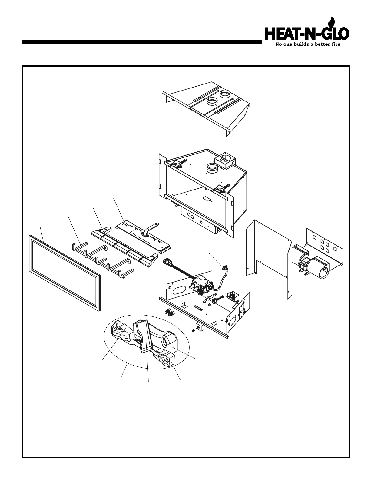
Service Parts
AT-ZC-B (NG, LP) Exploded Parts Diagram / AT-ZC-B (GN, PL) Vue éclatée des pièces
2
5
4
3
10
1
8
7
11
9
Part number list on following page.
*
La liste des numéros de pièce se trouve à la page suivante.
*
5
Page 6
AT-ZC-B (NG, LP) Service Parts List / AT-ZC-B (GN, PL) Liste des pièces de rechange
IMPORTANT: THIS IS DATED INFORMATION. The most current information is located on your dealers VIP site. When ordering,
supply serial and model numbers to ensure correct service parts. / IMPORTANT : L'information fournie dans cette brochure n'est
valide que pendant une courte période. Les sites VIP des distributeurs disposent des renseignements les plus récents. Lors
d'une commande, veuillez fournir les numéros de série et de modèles pour un remplacement adéquat des pièces.
ITE M /
PIÈCE
STANDING PILOT IGNITION SIT VALVE
/ ALLUMAGE UNE VEILLEUSE SIT VALVE
SERIAL # /
N° DE SÉRIE
PART NUMBER
/ N° DE PIÈCE
Valve NG / Valve GN 571-500
Valve LP / Valve PL 571-501
Pilot Assembly NG / Module de veilleuse GN 571-510A
Pilot Assembly PL / Module de veilleuse PL 571-511A
Pilot Orifice NG / Orifice de veilleuse GN 571-516
Pilot Orifice PL / Orifice de veilleuse PL 571-517
Thermocouple / Thermocouple 571-511
Thermopile / Thermopile 060-512
COMMON PARTS / PIÉCES COMMUNES
Piezo Ignitor / Allumag e Pi ézo 418-513
Junction Box - Pilot / Boîtier de ra ccordement - de veilleuse 040-250A
1 Burner Orifice NG (#42A) / Ori fice de brûleur GN (#42A ) 060-800
1 Burner Orifice LP (#53A) / Orifice de brûleur PL (#53A ) 060-801
2 Burner NG / Brûleur GN 485-275A
2 Burner LP / B rûleur PL 485-275A
3 Glass Door Assembly / Module de Porte en verre GLA-ATZC
4 Log Grate / Grille de Bûche 485-360A
5 Refractory / Réfr actair e SRV485-700
7 Log Set Assembly / Jeu de Bûches SRV485-701A
8 Log 1 / Bûche 1 SRV485-701
9 Log 2 / Bûche 2 SRV446-702
10 Log 3 / Bûche 3 SRV446-703
11 Log 4 / Bûche 4 SRV485-702
Conversion Kit NG / Module de conversion GN NGK-ATZC-CD N
Conversion Kit LP / Module de conversion PL LPK-ATZC-CDN
6
Page 7
1Approvals and Codes
Homologations et codes
Approval Listing and Codes
Appliance Certification
The Heat-N-Glo models discussed in this Installers Guide
have been tested to certification standards and listed by the
applicable laboratories.
CERTIFICATION STANDARD
MODEL AT-ZC-B
LABORATORY Underwriters Laboratories
TYPE Direct Vent Gas Fireplace Heater
STANDARD ANSI Z21.88CSA2.33UL307B
Installation Codes
The appliance installation must conform to local codes. Before
installing the appliance, consult the local building code
agency to ensure that you are in compliance with all
applicable codes, including permits and inspections.
In the absence of local codes, the appliance installation must
conform to the National Fuel Gas Code ANSI Z223.1 (in the
United States) or the CAN/CGA-B149 Installation Codes (in
Canada). The appliance must be electrically grounded in
accordance with local codes or, in the absence of local codes
with the National Electric Code ANSI/NFPA No. 70 (in the
United States), or to the CSA C22.1 Canadian Electric Code
(in Canada).
These models may be installed in a bedroom or bed-sitting
room in the U.S.A. and Canada.
Homologations et codes
Homologation de lappareil
Les modèles Heat-N-Glo dont il est question dans ce Guide
dinstallation ont été testés conformément aux normes
dhomologation et ont été approuvés par les laboratoires
compétents.
NORME DHOMOLOGATION
MODÈLE AT-ZC-B
LABORATOIRE Underwriters Laboratories
TYPE Cassette de cheminée à gaz à
système dévacuation directe
NORMES ANSI Z21.88CSA2.33UL307B
Codes dinstallation
Linstallation de lappareil doit être conforme aux codes
locaux. Avant dinstaller lappareil, consultez les autorités
locales en matière de codes de construction afin de vous
assurer que vous respectez tous les codes en vigueur, y
compris les permis de construire et les inspections.
En labsence de codes locaux, linstallation de lappareil doit
être conforme au code américain National Fuel Gas Code
ANSI Z223.1 (aux États-Unis) ou aux Codes des installations
CAN/CGA-B149 (au Canada). Lappareil doit être muni dun
fil de terre conformément aux codes locaux ou, en labsence
de codes locaux, au code américain National Electric Code
ANSI/NFPA n°70 (aux États-Unis) ou au Code électrique
canadien CSA C22.1 (au Canada).
Ces modèles peuvent être installés dans une chambre à
coucher ou une chambre-salon aux États-Unis et au Canada.
7
Page 8

Approvals and Codes (continued)
Homologations et codes (suite)
High Altitude Installations
U.L. Listed gas appliances are tested and approved for
elevations from 0 to 2,000 feet in the U. S. A. and are tested
and approved for elevations from 0 to 4,500 feet in Canada.
When installing this appliance at an elevation above 2,000
feet (in the United States), it may be necessary to decrease
the input rating by changing the existing burner orifice to a
smaller size. Input should be reduced four percent (4%) for
each 1,000 feet above sea level, unless the heating value of
the gas has been reduced, in which case this general rule
will not apply. To identify the proper orifice size, check with
the local gas utility.
When installing this appliance at an elevation between 2,000
and 4,500 feet (in Canada), the input rating must be reduced
by ten percent (10%).
When installing this appliance at an elevation above 4,500
feet (in Canada), check with local authorities.
Consult your local gas utility for assistance in determining
the proper orifice for your location.
Installation à haute altitude
Les appareils à gaz homologués U.L. ont été testés et
approuvés pour fonctionner entre 0 et 610 mètres daltitude
aux États-Unis et entre 0 et 1.370 mètres daltitude au
Canada.
Si cet appareil est installé à une altitude supérieure à 610
mètres (aux États-Unis), il peut savérer nécessaire de
réduire ladmission du gaz en diminuant louverture de lorifice
du brûleur. Ladmission doit être réduite de quatre pour cent
(4%) par 305 mètres au-dessus du niveau de la mer, à moins
que le pouvoir calorifique du gaz ait été réduit. Dans ce cas,
cette règle générale ne sapplique pas. Pour connaître
louverture de lorifice qui convient, consultez le service local
de distribution de gaz.
Si cet appareil est installé entre 610 et 1.370 mètres daltitude
(au Canada), ladmission du gaz doit être réduite de dix
pour cent (10%).
Si cet appareil est installé à une altitude supérieure à 1.370
mètres (au Canada), consultez les autorités locales.
Consultez votre service local de distribution de gaz afin de
déterminer le diamètre de lorifice requis pour votre région.
8
Page 9

2
Getting Started
Comment débuter
Introducing the
Heat-N-Glo Gas Appliances
Heat-N-Glo direct vent gas appliances are designed to operate with all combustion air siphoned from outside of the building and all exhaust gases expelled to the outside. The information contained in this Installers Guide, unless noted otherwise, applies to all models and gas control systems. Gas
appliance diagrams, including the dimensions, are shown in
this section.
Pre-installation Preparation
This gas insert and its components are tested and safe when
installed in accordance with this Installers Guide. Report to
your dealer any parts damaged in shipment, particularly the
condition of the glass. Do not install any unit with
damaged, incomplete, or substitute parts.
The vent system components and trim surrounds are shipped
in separate packages. The gas logs are packaged separately
and must be field installed. Read all of the instructions
before starting the installation. Follow these instructions
carefully during the installation to ensure maximum
safety and benefit. Failure to follow these instructions
will void the owners warranty and may present a fire
hazard.
The Heat-N-Glo, a division of Hearth Technologies Inc.
Warranty will be voided by, and Heat-N-Glo disclaims any
responsibility for, the following actions:
Installation of any damaged appliance or vent system
component.
Modification of the appliance or direct vent system.
Installation other than as instructed by Heat-N-Glo.
Improper positioning of the gas logs or the glass door.
Installation and/or use of any component part not manu-
factured and approved by Heat-N-Glo, not withstanding
any independent testing laboratory or other party approval
of such component part or accessory.
ANY SUCH ACTION MAY POSSIBLY CAUSE A FIRE HAZARD.
Présentation des appareils à gaz
Heat-N-Glo
Les appareils à gaz à évacuation directe Heat-N-Glo sont
conçus pour aspirer tout lair de combustion de lextérieur de
lédifice et expulser tous les gaz de combustion en dehors
de lédifice. Les informations contenues dans ce Guide
dinstallation, sauf dans le cas de mention contraire,
sappliquent à tous les modèles et à tous les systèmes de
commande de gaz. Cette section comprend des schémas
de lappareil à gaz, avec ses dimensions.
Préparation avant linstallation
Cette cassette à gaz et ses éléments ont été testés et ne
présentent aucun danger sils sont installés conformément
à ce Guide dinstallation. Signalez à votre concessionnaire
toutes pièces endommagées lors du transport, en particulier
sil sagit de la porte en verre. Ninstallez aucun appareil
dont des pièces sont endommagées, sont incomplètes
ou ont été remplacées par des pièces différentes.
Les éléments du système dévacuation et les entourages
sont expédiés dans différents colis. Les bûches à gaz sont
emballées séparément et doivent être installées sur place.
Lisez toutes les instructions avant de commencer
linstallation. Suivez attentivement ces instructions
pendant linstallation afin dassurer une sécurité et une
efficacité optimales. Si ces instructions ne sont pas
suivies, la garantie sera annulée et vous pourriez
causer un incendie.
La garantie Heat-N-Glo, division de Hearth Technologies Inc.,
sera annulée par les actes suivants, pour lesquels Heat-NGlo décline toute responsabilité:
Installation déléments endommagés dans lappareil ou
dans le système dévacuation.
Modification de lappareil ou du système dévacuation
directe.
Installation différente de celle indiquée par Heat-N-Glo.
Placement incorrect des bûches à gaz ou de la porte en
verre.
Installation et/ou utilisation de pièces nayant pas été
fabriquées et approuvées par Heat-N-Glo, même si cette
pièce ou cet accessoire a été homologué par un laboratoire
dessais indépendant ou un autre organisme compétent.
CES ACTES POURRAIENT CAUSER UN INCENDIE.
9
Page 10

Getting Started (continued)
Comment débuter (suite)
VENTING AND INSTALLATION
1. Heat-N-Glo gas inserts are designed for recessed installations into solid fuel Masonry or Factory Built Non Combustible fireplaces that have been installed in accordance
with the National, Provincial, State and local building
codes.
2. Minimum fireplace opening requirements are shown in
Figure 1 of this installation manual. The firebrick (refractory) can be removed from a factory built fireplace in order
to gain minimum gas insert opening requirements.
3. To assure top performance, safety and efficiency, inserts
must be installed with an approved flue liner as per CAN/
CGA B-149 or National Fuel Code ANSI Z223 and these
instructions.
WARNING: THE SOLID FUEL FIREPLACE HAS
!
BEEN CONVERTED FOR USE WITH GAS ONLY
AND CANNOT BE USED FOR BURNING WOOD
OR SOLID FUELS UNLESS ALL ORIGINAL PARTS
HAVE BEEN REPLACED AND THE FIREPLACE HAS
BEEN REAPPROVED BY THE AUTHORITY HAVING
JURISDICTION.
4. The solid fuel fireplaces flue damper must be fully locked
in the open position or removed for installation.
5. The chimney must be cleaned and in good working order
and constructed of noncombustible materials.
6. Make sure that all chimney cleanouts fit properly so air
cannot leak into the chimney.
ÉVACUATION ET INSTALLATION
1. Les cassettes à gaz Heat-N-Glo sont conçues pour être
encastrées dans des cheminées en matériaux non combustibles, en maçonnerie ou préfabriquées, à combustible solide, qui ont été installées conformément aux
codes de construction nationaux, provinciaux et locaux.
2. Les spécifications douverture minimum de la cheminée
sont indiquées sur la Figure1 de ce manuel dinstallation.
Les briques réfractaires peuvent être retirées dune
cheminée préfabriquée afin dobtenir louverture minimum
spécifiée pour la cassette à gaz.
3. Afin dobtenir des performances, une sécurité et une
efficacité optimales, les cassettes doivent être installées
avec un revêtement de conduit approuvé, conformément
aux codes CAN/CGA B-149 ou au code américain Na-
tional Fuel Code ANSI Z223 et à ces instructions.
AVERTISSEMENT: LA CHEMINÉE À COMBUS-
!
TIBLE SOLIDE A ÉTÉ CONVERTIE POUR ÊTRE
UTLISÉE SEULEMENT AVEC DU GAZ ET NE
PEUT PLUS ÊTRE UTILISÉE POUR BRÛLER DU BOIS
OU DAUTRES COMBUSTIBLES SOLIDES, À MOINS
QUE TOUTES LES PIÈCES DORIGINE NE SOIENT
REMISES EN PLACE ET QUE LA CHEMINÉE NAIT
ÉTÉ À NOUVEAU APPROUVÉE PAR LES AUTORITÉS
COMPÉTENTES.
4. Le registre du tuyau de la cheminée à combustible solide
doit être verrouillé en position douverture maximale ou
bien démonté pour linstallation.
7. Install the insert without the trim surround and make all
gas, venting, and electrical connections.
WARNING: Under no circumstances is cutting
!
of sheet metal surfaces allowed for installation.
If the factory built fireplace has no gas access holes
provided, an access hole of 1 diameter (25mm) or
less may be drilled through the lower sides or bottom of the combustion chamber in a proper workmanship like manner.
8. Install decorative trim surround. Please refer to instructions included with the trim surround.
Ensure there are no obstructions to side air
!
passages of decorative trim once installed
on insert.
5. La cheminée doit être nettoyée, en bon état de
fonctionnement et composée de matériaux non combustibles.
6. Vérifiez que toutes les portes de ramonage soient bien
ajustées afin que lair ne puisse pas entrer dans la
cheminée.
7. Installez la cassette sans lentourage et effectuez tous
les raccords de gaz et dévacuation, ainsi que tous les
branchements électriques.
AVERTISSEMENT: Le découpage de tôles
!
nest en aucun cas autorisé pour faciliter
linstallation.
Si la cheminée préfabriquée ne comporte aucun
orifice darrivée de gaz, un orifice daccès de
25mm de diamètre maximum peut être percé au
bas des parois latérales ou au fond du foyer, de
manière appropriée.
8. Installez lentourage décoratif. Veuillez consulter les instructions incluses avec lentourage.
Une fois lentourage décoratif installé sur la
!
cassette, vérifiez que ses conduits dair
latéraux ne soient pas obstrués.
10
Page 11

Getting Started (continued)
Comment débuter (suite)
When planning a fireplace insert installation, its necessary
to determine:
The vent system configuration to be used.
Gas supply piping.
Whether optional accessoriesdevices such as a wall
switch, or remote controlare desired.
Figure 1. Diagram of the AT-ZC-B
7 1/4 (2)
(184mm)
2 1/8
(54mm)
GAS LINE ACCESS/
ACCÉSS DU
CONDUIT
Á GAZ
Avant de commencer linstallation de la cassette de cheminée,
il est nécessaire de déterminer:
La configuration du système dévacuation qui sera utilisée.
La tuyauterie dalimentation en gaz.
Si vous désirez installer des accessoires facultatifs
(dispositifs tels quun interrupteur mural ou une commande
à distance).
Figure 1. Schéma de la cassette AT-ZC-B
14 ½ (368mm)
7 1/8
(181mm)
14
(355mm)
1
(25mm)
14 5/8
(371mm)
FAN ACCESS
COVER/
COUVERTURE D'ACCÈS DE
SUPPORTER(VENTILATEUR)
14
3 3/16
(81mm)
4 7/8 (124mm)
15
TOP VIEW/
VUE DU DESSUS
23 3/4
28 11/16
(729mm)
RATING PLAT E/
PLAQUE DE
CARACTERISTIQUES
GAS CONTROL VALVE/
COMMANDE DE GAZ
MANUAL VALVE &
FLEX CONNECTOR
VALVE MANUELLE ET
FLÉCHIT CONNECTEUR
MINIMUM APPLIANCE SIZE
FRONT WIDTH : 23
REAR WIDTH : 15
DEPTH : 14
* HEIGHT : 20
* NOTE: If exhaust collar on insert and
fireplace damper do not line up, add 4
inches (102mm) to minimum fireplace
height for bends in vent pipe.
FAN SWITCH/
COMMUTATEUR DE
SUPPORTER(VENTILATEUR)
3/4
18 3/4
(476mm)
ELECTRICAL ACCESS/
ALIMENTATION
ELECTRIQ UE
* HAUTEUR : 508mm
* REMARQUE: Si le collet dévacuation de
18
(457mm)
2 1/8
(54mm)
4 11/16
(119mm)
EXHAUST STARTING COLLAR/
COLLIER DE DEPART
D’ADMISSION D’AIR
INLET STARTING COLLAR/
COLLET DE RACCORD DU
CONDUIT D’ADMISSION D’AIR
ELECTRICAL
ACCESS/
ALIMENTATION
ELECTRIQUE
DIMENSIONS MINIMUM DE LAPPAREIL
LARGEUR AVANT : 603mm
LARGEUR ARRIÈRE: 572mm
PROFONDEUR : 356mm
la cassette et le registre de la cheminée
ne salignent pas, ajoutez 102mm à la
hauteur minimale de la cheminée pour
les coudes du conduit dévacuation.
11
Page 12

3
Installing the Insert
Installation de la cassette
Step 1
Installing the Vent System
Vent System Installation Precautions
Before starting installation of vent kits, the installer should
read these instructions and the Vent Kit Instructions to
ensure that a proper vent installation is completed. Consult
your local Building Codes before beginning the Installation.
WARNING: THIS GAS INSERT AND VENT
!
ASSEMBLY MUST BE VENTED DIRECTLY TO
THE OUTSIDE AND MUST NEVER BE ATTACHED TO
A CHIMNEY SERVING A SEPARATE SOLID FUEL
BURNING APPLIANCE. EACH GAS APPLIANCE
MUST USE A SEPARATE VENT SYSTEM. COMMON
VENT SYSTEMS ARE PROHIBITED.
Vent System Approvals
Table 1 and Figure 3 through 5 show the vent termination
caps and systems approved for use with these models.
Approved vent system terminations are labeled for
identification. 3-inch diameter listed flexible aluminum or
stainless steel gas vent is used for both the incoming
combustion air and exhaust vent pipes. NO OTHER
VENTING SYSTEMS OR COMPONENTS MAY BE USED.
Detailed installation instructions are included with each vent
termination kit and should be used in conjunction with this
manual.
Horizontal Venting
The vent system on this model CANNOT be terminated
horizontally.
Vertical Venting
The vent pipes MUST be connected to the proper collars on
the unit AND the exhaust vent pipe MUST be connected to
the termination cap or the unit will not operate. The
combustion air vent pipe CAN be connected to the
termination cap or it can terminate inside the chimney. The
bottom opening of the chimney must be sealed around the
vent pipes if the combustion air vent is NOT connected to
the termination cap. See Figures 3, 4 and 5.
NOTE: The minimum vertical rise (exhaust vent) is 14 feet
and the maximum vertical rise is 50 feet. These dimensions
are measured from the starting collars of the unit to the end
of the last section of vent pipe. See dimension V in Figure 3.
Étape 1
Installation du système dévacuation
Précautions dinstallation du système dévacuation
Avant de commencer à installer les modules dévacuation,
linstallateur doit lire ces instructions et celles des modules
dévacuation afin dobtenir une installation correcte.
Consultez les codes de construction de votre région avant
de commencer linstallation.
AVERTISSEMENT: CETTE CASSETTE À GAZ
!
ET CE SYSTÈME DÉVACUATION DOIVENT ÉVACUER LES GAZ DE COMBUSTION DIRECTEMENT
À LEXTÉRIEUR ET NE DOIVENT JAMAIS ÊTRE RACCORDÉS À UNE CHEMINÉE DESSERVANT UN AUTRE APPAREIL À COMBUSTIBLE SOLIDE. CHAQUE
APPAREIL À GAZ DOIT UTILISER UN SYSTÈME DÉVACUATION DISTINCT. LUTILISATION DE SYSTÈMES DÉVACUATION EN COMMUN EST INTERDITE.
Homologation du système dévacuation
Le Tableau1 et les Figures3 à 5 représentent les capuchons
et les systèmes dévacuation homologués pour utilisation
avec ces modèles. Les terminaisons de système
dévacuation homologuées portent une étiquette
didentification. Des conduits flexibles homologués de
76mm de diamètre, en aluminium ou en acier inoxydable,
servent à laspiration de lair de combustion et à lévacuation
des gaz de combustion. AUCUN AUTRE SYSTÈME OU
ÉLÉMENT DÉVACUATION NE PEUT ÊTRE UTILISÉ. Des
instructions dinstallation détaillées sont incluses avec
chaque module de terminaison de système dévacuation et
doivent être utilisées en conjonction avec ce manuel.
Évacuation horizontale
Le système dévacuation de ce modèle NE PEUT PAS
comporter de terminaison horizontale.
Évacuation verticale
Les conduits DOIVENT être raccordés aux collets correspondants de lappareil ET le conduit dévacuation DOIT être
raccordé au capuchon pour que lappareil puisse fonctionner.
Le conduit dair de combustion PEUT être raccordé au
capuchon ou aboutir à lintérieur de la cheminée. Louverture
inférieure de la cheminée doit être jointe hermétiquement
aux conduits si le conduit dair de combustion nest PAS
raccordé au capuchon. Voir Figures3, 4 et5.
REMARQUE: La longueur verticale (conduit dévacuation)
doit être comprise entre 4,3mètres et 15,2 mètres. Cette
dimension est mesurée entre les collets de raccord de
lappareil et lextrémité de la dernière section de conduit
dévacuation. Voir la dimensionV sur la Figure3.
12
Page 13

Installing the Insert (continued)
Installation de la cassette (suite)
A vertical vent termination system installed on this model
will include one (1) length of 3-inch flexible vent pipe for the
combustion air, one (1) pipe-to-cap adaptor, and one (1) SLK991DA or SLK-980D vertical termination cap.
NOTE: The damper of the masonry chimney may need to be
removed to allow installation of the flexible-vent pipe.
This fireplace has been altered to accommodate an insert
and should be inspected by a qualified person prior to
re-use as a conventional fireplace.
NOTE: The above label, located in the instruction package,
must be affixed to the existing fireplace prior to installation
of Model AT-ZC-B.
For zero clearance factory built woodburning fireplaces, the
use of kit LINK-ZC-ADP, in place of the standard square
flashing, will allow you to mount the adaptor and cap on
metal pipe. Additionally, the use of kit FLASH-DAMP will
seal off the damper opening when terminating the inlet air
vent pipe just above the damper. These two kits are
recommended for zero clearance, factory built woodburning
fireplaces.
Connecting the Vent Pipe
Install the 3-inch flexible vent pipes down through the chimney.
Attach and secure the bottom ends of the flex pipes to the
starting collar bracket with 3 sheetmetal screws on each collar.
Slide the gas insert into place, and position any excess flex
vent pipe back up into the chimney.
NOTE: Optional ZC-ADP Kit can be attached to the top of
the unit and will increase the depth of the units starting
collars if needed. See Figures 4 and 5.
Attach the pipe-to-cap adaptor to the termination cap and
the top of the flexible vent pipe and set the cap in place at
the top of the chimney. See Figures 3, 4 & 5.
CAUTION: TO AVOID DOWNDRAFTS AND/OR COLD AIR
PROBLEMS, IT IS RECOMMENDED TO SEAL OFF THE
AREA BETWEEN THE TERMINATION CAP AND THE TOP
OF THE SOLID-FUEL CHIMNEY OPENING INTO WHICH
THE VENT CAP HAS BEEN INSTALLED.
WHEN USING THE LINK-DV4-30 VENT SYSTEM, IT IS
REQUIRED TO SEAL AROUND THE FLEXIBLE VENT
PIPES IN THE DAMPER AREA. SEE FIGURE 3. USE
FIBERGLASS INSULATION OR OTHER SUITABLE NONCOMBUSTIBLE MATERIAL.
VENT SYSTEM APPROVALS
AT-ZC-B LINK-DV30
LINK-DV4-30
TABLE 1
Un système dévacuation à terminaison verticale installé sur
ce modèle doit inclure un (1)conduit flexible dair de combustion de 76mm de long, un (1)raccord conduit/capuchon et
un (1)capuchon vertical SLK-991DA ou SLK-980D.
REMARQUE: Il sera peut-être nécessaire de démonter le
registre de la cheminée en maçonnerie pour permettre
linstallation du conduit flexible.
Cette cheminée a été modifiée pour pouvoir recevoir une
cassette et doit être inspectée par une personne qualifiée
avant dêtre réutilisée en tant que cheminé traditionnelle.
REMARQUE: Létiquette ci-dessus, qui se trouve dans le
paquet dinstructions, doit être apposée sur la cheminée
existante avant linstallation du modèle AT-ZC-B.
Sur les cheminées à bois préfabriquées sans dégagement,
lutilisation du module LINK-ZC-ADP, au lieu du solin carré
standard, vous permettra de monter le raccord et le capuchon
sur un conduit métallique. Par ailleurs, lutilisation du module
FLASH-DAMP bouchera hermétiquement louverture du
registre si le conduit dadmission dair débouche juste audessus du registre. Ces deux modules sont recommandés
sur les cheminées à bois préfabriquées sans dégagement.
Raccord du conduit dair
Faites passer les conduits flexibles de 76mm dans la cheminée.
Fixez lextrémité inférieure des conduits flexibles au support
de collet de raccord à laide de 3 vis à tôle sur chaque collet.
Insérez la cassette et renfoncez toute longueur excessive de
conduit flexible dans la cheminée.
NOTEZ : le Kit de ZC-ADP facultatif peut être attaché au
sommet de lunité et augmentera la profondeur des cols de
départ de lunité si nécessaire. Voir les Figures 4 et 5.
Fixez le raccord conduit/capuchon sur le capuchon et le
haut du conduit flexible, puis mettez le capuchon en place
en haut de la cheminée. Consultez les Figures3, 4 et5.
ATTENTION: POUR ÉVITER LES PROBLÈMES DE
REFOULEMENT ET/OU DE COURANTS DAIR FROID, IL
EST RECOMMANDÉ DE BOUCHER HERMÉTIQUEMENT
LESPACE ENTRE LE CAPUCHON ET LE HAUT DE
LOUVERTURE DE LA CHEMINÉE À COMBUSTIBLE
SOLIDE SUR LAQUELLE LE CAPUCHON A ÉTÉ
INSTALLÉ.
AVEC LE SYSTÈME DÉVACUATION LINK-DV4-30, IL EST
OBLIGATOIRE DE BOUCHER HERMÉTIQUEMENT LES
JOINTS DES CONDUITS FLEXIBLES AUTOUR DU
REGISTRE. CONSULTEZ LA FIGURE3. UTILISEZ DE
LISOLANT DE FIBRE DE VERRE OU UN AUTRE
MATÉRIAU NON COMBUSTIBLE ADAPTÉ.
HOMOLOGATION DU SYSTÈME DÉVACUATION
AT-ZC-B LINK-DV30
LINK-DV4-30
TABLEAU 1
13
Page 14

Installing the Insert (continued)
Installation de la cassette (suite)
WARNING: MAJOR U.S. BUILDING CODES
!
SPECIFY MINIMUM CHIMNEY AND/OR VENT
HEIGHT ABOVE THE ROOF TOP. THESE
MINIMUM HEIGHTS ARE NECESSARY IN THE
INTEREST OF SAFETY. SEE THE FOLLOWING
DIAGRAM FOR MINIMUM HEIGHTS, PROVIDED
THE TERMINATION CAP IS AT LEAST 2-FEET
FROM A VERTICAL WALL AND 2 FEET BELOW
A HORIZONTAL OVERHANG.
Note: This also pertains to vertical vent systems installed
on the outside of the building.
AVERTISSEMENT: LES PRINCIPAUX CODES DE
!
CONSTRUCTION AMÉRICAINS DÉFINISSENT LA
HAUTEUR MINIMALE DE LA CHEMINÉE ET/OU
DU CONDUIT DÉVACUATION AU-DESSUS DU
TOIT. CES HAUTEURS MINIMALES SONT
NÉCESSAIRES POUR DES RAISONS DE
SÉCURITÉ. CONSULTEZ LE SCHÉMA SUIVANT
POUR CONNAÎTRE LES HAUTEURS MINIMALES
À RESPECTER LORSQUE LE CAPUCHON EST
ÉLOIGNÉ DAU MOINS 61CM DUN MUR
VERTICAL ET AU-DESSOUS DUN SURPLOMB.
Remarque: Ces restrictions sappliquent également aux
systèmes dévacuation verticale installés à lextérieur de
lédifice.
ROOF PITCH H (MIN.) FT.
Flat to 6/12 1.0
6/12 to 7/12 1.25
Over 7/12 to 8/12 1.5
Over 8/12 to 9/12 2.0
Over 9/12 to 10/12 2.5
Over 10/12 to 11/12 3.25
Over 11/12 to 12/12 4.0
Over 12/12 to 14/12 5.0
Over 14/12 to 16/12 6.0
Over 16/12 to 18/12 7.0
Over 18/12 to 20/12 7.5
Over 20/12 to 21/12 8.0
Figure 2. Minimum height from roof to lowest
discharge opening
PENTE DU TOIT H (MINI.) EN CM
De plat à 6/12 30
De 6/12 à 7/12 38
De 7/12 à 8/12 46
De 8/12 à 9/12 61
De 9/12 à 10/12 76
De 10/12 à 11/12 99
De 11/12 à 12/12 122
De 12/12 à 14/12 152
De 14/12 à 16/12 183
De 16/12 à 18/12 213
De 18/12 à 20/12 229
De 20/12 à 21/12 244
Figure 2. Hauteur minimum entre le toit et
louverture dévacuation la plus
basse
14
Page 15

Installing the Insert (continued)
TERMINATION CAP/
CAPUCHON
ADAPTOR/
RACCORD
EXHAUST VENT PIPE/
CONDUIT
DEVACUATION
Installation de la cassette (suite)
THIS OPTION SHOWS BOTH EXHAUST AND INLET AIR VENT PIPES
ATTACHED TO THE ADAPTOR.
CETTE OPTION REPRÉSENTE LES
CONDUITS DÉVACUATION ET
DADMISSION DAIR ATTACHÉS AU
RACCORD.
PLACE INSULATION HERE
AROUND DAMPER AREA/
ISOLATION DE PLACE ICI
AUTOUR DE SECTEUR
DHUMECTEUR.
V= 14FT. MINIMUM
50FT . MAXIMUM
WARNING: DO NOT BLOCK PIPE END WITH
INSULATION OR ANY OTHER SEALING MATERIAL/
AVERTISSEMENT : NE BLOQUEZ PAS LA FIN DE PIPE AVEC
LISOLATION OU UN AUTRE MATÉRIEL DE CACHETAGE.
INLET AIR VENT
PIPE/ CONDUIT
DADMISSION
DAIR
Figure 3.
WARNING: THE EXHAUST PIPE MUST ONLY BE
!
CONNECTED TO THE EXHAUST STARTING
COLLAR OF THE UNIT AND THE CENTER COLLAR
OF THE TERMINATION CAP.
THE INLET AIR PIPE MUST ONLY BE CONNECTED
TO THE INLET AIR COLLAR OF THE UNIT AND EITHER ATTACHED TO THE INLET AIR COLLAR OF THE
TERMINATION CAP OR TERMINATED IN THE CHIMNEY.
15
Figure 3.
AVERTISSEMENT: LE CONDUIT DÉVACUA-
!
TION DOIT ÊTRE RACCORDÉ SEULEMENT AU
COLLET DE RACCORD DU SYSTÈME DÉVACUATION
DE LAPPAREIL ET AU COLLET CENTRAL DU
CAPUCHON.
LE CONDUIT DADMISSION DAIR DOIT ÊTRE
RACCORDÉ SEULEMENT AU COLLET CORRESPONDANT DE LAPPAREIL ET SOIT ÊTRE ATTACHÉ AU
COLLET CORRESPONDANT DU CAPUCHON, SOIT
DÉBOUCHER DANS LA CHEMINÉE.
Page 16

Installing the Insert (continued)
INLET AIR STARTING COLLAR/
COLLET DE RACCORD DU
CONDUIT D’ADMISSION D’AI R
Installation de la cassette (suite)
TERMINATION
CAP/ CAPUCHON
ADAPTOR/
RACCORD
EXHAUST
COLLAR/
COLLET
D’EVACUATION
D’ADMISSION
INLET AIR
COLLAR/
COLLET
D’AIR
EXHAUST STARTING COLLAR/
COLLET DE RACCORD DU
CONDUIT D’EVACUATION
Figure 4
Figure 5
(OPTIONAL/EN OPTION)
ZC-ADP
16
Page 17

Installing the Insert
(continued)
Installation de la cassette
(suite)
Step 2
Positioning, Leveling, and
Securing Insert
1. Place the insert into position.
2. Level the insert from side to side and from front to back.
If necessary use the legs included in the manual bag.
Screw the legs into the nuts installed in the bottom
rear of the insert. Turn legs in until insert is level.
Step 3
The Gas Control Systems
WARNING: THIS UNIT IS NOT FOR USE WITH
!
SOLID FUEL.
The gas control system used with this model is Standing
Pilot Ignition.
Standing Pilot Ignition System
This system includes millivolt control valve, standing pilot,
thermopile/thermocouple flame sensor, and piezo ignitor.
WARNING: 110-120 VAC MUST NEVER BE
!
CONNECTED TO A CONTROL VALVE IN A
MILLIVOLT SYSTEM.
Étape 2
Emplacement, nivellement et
solidification de la cassette
1. Placez la cassette à lemplacement désiré.
2. Nivelez la cassette dun côté à lautre et de lavant à
larrière.
Si nécessaire, utilisez les pieds inclus dans la
pochette du manuel. Vissez les pieds dans les écrous
installés au bas de la cassette, à larrière. Vissez les
pieds jusquà ce que la cassette soit nivelée.
Étape 3
Systèmes de commande de gaz
AVERTISSEMENT: CET APPAREIL NE DOIT
!
PAS ÊTRE UTILISÉ AVEC DES COMBUSTIBLES SOLIDES.
Le type de commande de gaz utilisé sur ce modèle est
lallumage par veilleuse.
Système dallumage par veilleuse
Ce système comprend une valve de commande millivolt,
une veilleuse, un détecteur de flamme à thermopile/
thermocouple et un allumeur piézo.
AVERTISSEMENT: UN COURANT ÉLEC-
!
TRIQUE DE 110-120VCA NE DOIT JAMAIS
ÊTRE BRANCHÉ À UN SYSTÈME DE VALVE
DE COMMANDE MILLIVOLT.
STANDING PILOT
Figure 6.
Gas Controls Systems
(VEILLEUSE)
3/8" (10 mm)
Figure 6.
Systèmes de
commande de gaz
17
Page 18

Installing the Insert (continued)
Installation de la cassette (suite)
Step 4
The Gas Supply Line
NOTE: Have the gas supply line installed in accordance
with local building codes by a qualified installer
approved and/or licensed as required by the locality.
(In the state of Massachusetts installation must be
performed by a licensed plumber or gas fitter).
NOTE: Before the first firing of the fireplace, the gas
supply line should be purged of any trapped air.
NOTE: Consult local building codes to properly size
the gas supply line leading to the 1/2 inch
(13 mm) hook-up at the unit.
This gas fireplace is designed to accept a 1/2 inch
(13 mm) gas supply line. To install the gas supply line:
A listed (and State of Massachusetts approved) 1/2 inch
(13mm) tee-handle manual shut-off valve and a listed
flexible gas connector are connected to the 3/8 inch
(9.5mm) inlet of the control valve. NOTE: If substituting
for these components, please consult local codes for
compliance.
The gas line may be run from either side of the fireplace
provided the hole in the outer wrap does not exceed 2
in diameter and it does not penetrate the airtight firebox.
The gap between the supply piping and gas access hole
can be plugged with non-combustible insulation to prevent cold air infiltration.
Locate the gas line access hole in the outer casing of
the insert.
Open the lower grille, insert the gas supply line through
the gas line hole, and connect it to the shut-off valve.
When attaching the pipe, support the control so that
the lines are not bent or torn.
After the gas line installation is complete, use a soap
solution to carefully check all gas connections for leaks.
Étape 4 Conduit à gaz
REMARQUE: Le conduit dalimentation en gaz doit être
installé conformément aux codes de construction locaux
par un installateur qualifié, approuvé et/ou agréé selon
les spécifications de la localité. (Dans lÉtat du
Massachusetts, linstallation doit être effectuée par un
plombier ou un installateur dappareils à gaz agréé.)
REMARQUE: Avant dallumer le foyer pour la première
fois, toutes les bulles dair doivent être évacuées du
conduit à gaz.
REMARQUE: Consultez les codes de construction locaux
pour choisir correctement le diamètre du conduit à gaz
sacheminant vers le raccord de 13mm du foyer.
Ce foyer à gaz est conçu pour accepter un conduit à gaz de
13mm. Pour installer le conduit à gaz:
Un robinet manuel à poignée en T de 13 mm (1/2 po)
homologué (et approuvé par l'État du Massachusetts) et
un tuyau à gaz flexible homologué sont branchés à l'orifice
d'admission de la valve de commande de 9.5 mm (3/8 po).
REMARQUE : Veuillez consulter les codes locaux pour
vous assurer que les éléments de remplacement sont
réglementaires.
Le conduit à gaz peut arriver dun côté ou de lautre du
foyer, à condition que lorifice pratiqué dans lextérieur du
foyer ne dépasse pas 50,8mm de diamètre et que le conduit ne pénètre pas dans le foyer hermétique.
Lécart entre la tuyauterie dapprovisionnement et lorifice
daccès du conduit à gaz peut être bouché à laide disolant
non combustible pour empêcher linfiltration dair froid.
Repérez lorifice daccès du conduit à gaz dans la paroi
extérieure de la cassette.
Ouvrez la grille inférieure, insérez le conduit à gaz dans
lorifice daccès du conduit à gaz et branchez-le au robinet.
Pour brancher le tuyau, soutenez la commande afin que
les conduits ne soient pas tordus ou rompus.
Une fois linstallation du conduit à gaz terminée, utilisez
une solution savonneuse pour détecter des fuites sur tous
les raccords de gaz.
WARNING: DO NOT USE AN OPEN FLAME TO
!
CHECK FOR GAS LEAKS.
Figure 7. Gas Supply Line
CONTROL VALVE/
COMMANDE DE GAZ
AVERTISSEMENT: NUTILISEZ PAS DE FLAMME
!
NUE POUR DÉTECTER DES FUITES DE GAZ.
MANUAL
SHUT-OFF VALVE
(ROBINET MANUEL)
GAS VALVE
(VALVE DE
COMMANDE DE GAZ)
Figure 7. Conduit à gaz
18
USE A WRENCH
ON SHUT-OFF VALVE
WHEN TIGHTENING
GAS LINE
(UTILISEZ UNE CLÉ SUR LE
ROBINET DE GAZ LORS
DU SERRAGE DU
CONDUIT À GAZ)
FLEX CO NNECTOR
(TUYAU FLEXIBLE)
Page 19

Installing the Insert (continued)
Installation de la cassette (suite)
Step 5
Gas Pressure Requirements
Pressure Natural Gas Propane
Minimum 5.0 inches 11.0 inches
Inlet Pressure w.c. w.c.
Maximum Inlet 14.0 inches 14.0 inches
Gas Pressure w.c. w.c.
Manifold 3.5 inches 10. 0 inches
Pressure w.c. w.c.
A one-eighth (1/8) inch (3 mm) N.P.T. plugged tapping is
provided on the inlet and outlet side of the gas control for a
test gauge connection to measure the manifold pressure.
Use a small flat blade screwdriver to crack open the screw
in the center of the tap. Position a rubber hose over the tap
to obtain the pressure reading.
The fireplace and its individual shut-off valve MUST be
disconnected from the gas supply piping system during
any pressure testing of the system at test pressures in
excess of one-half (1/2) psig (3.5 kPa).
Étape 5
Spécifications de la pression du gaz
Pression Gaz naturel Propane
Pression minimale 127mm 279mm
dapprovisionnement CE CE
Pression maximale 356mm 356mm
dapprovisionnement CE CE
Pression du 89 mm 254 mm
collecteur CE CE
Une dérivation de visite NPT de 3mm est prévue sur le
côté dadmission et sur le côté de sortie de la commande
de gaz, afin dy brancher un manomètre pour mesurer la
pression du collecteur. Utilisez un petit tournevis plat pour
entrouvrir la vis au centre de la dérivation. Placez un tuyau
en caoutchouc sur la dérivation pour mesurer la pression.
Le foyer et son robinet individuel DOIVENT être isolés de
la tuyauterie dalimentation en gaz pendant les contrôles
de pression du système à des pressions dessai supérieures
à 3,5kPa.
The fireplace MUST be isolated from the gas supply piping
system by closing its individual shut-off valve during any
pressure testing of the gas supply piping system at test
pressures equal to or less than one-half (1/2) psig (3.5 kPa).
Le foyer DOIT être isolé de la tuyauterie dalimentation en
gaz en fermant son robinet individuel pendant les contrôles
de pression de la tuyauterie dalimentation en gaz à des
pressions dessai inférieures ou égales à 3,5kPa.
19
Page 20

Installing the Insert
(continued)
Installation de la cassette
(suite)
Step 6
Wiring the Fireplace
NOTE: Electrical wiring must be installed by a licensed
electrician.
CAUTION: DISCONNECT REMOTE CONTROLS IF YOU
ARE ABSENT FOR EXTENDED TIME PERIODS. THIS
WILL PREVENT ACCIDENTAL FIREPLACE OPERATION.
For Standing Pilot Ignition Wiring
Appliance Requirements
This appliance DOES NOT require 110-120 VAC to oper-
ate.
WARNING: DO NOT CONNECT 110-120 VAC TO
!
THE GAS CONTROL VALVE OR THE
APPLIANCE WILL MALFUNCTION AND THE
VALVE WILL BE DESTROYED.
Optional Accessories
Optional fan and remote control kits require that 110-120
VAC be supplied to the factory installed junction box. Run
the cord out the notch in the surround and plug into a
convenient outlet.
Wall Switch
Position the wall switch in the desired position on a wall.
Run a maximum of 25 feet (7.8 m) or less length of 18
A.W.G. minimum wire and connect it to the fireplace valve
pigtails.
Étape 6
Filage électrique du foyer
REMARQUE: Le filage électrique doit être effectué par
un électricien agréé.
ATTENTION: DÉBRANCHEZ LES COMMANDES À DISTANCE SI VOUS VOUS ABSENTEZ POUR DES PÉRIODES PROLONGÉES. DE CETTE FAÇON, LE FOYER
NE POURRA PAS SALLUMER ACCIDENTELLEMENT.
Filage de lallumage par veilleuse
Spécifications de lappareil
Le fonctionnement de cet appareil NE nécessite PAS de
courant électrique de 110-120VCA.
AVERTISSEMENT: NE BRANCHEZ PAS DE
!
COURANT ÉLECTRIQUE DE 110-120VCA À
LA VALVE DE COMMANDE DE GAZ. CELA
ENTRAÎNERAIT UN MAUVAIS FONCTIONNEMENT
DE LAPPAREIL ET LA DESTRUCTION DE LA VALVE.
Accessoires facultatifs
Les ensembles facultatifs de ventilateur et de commande à
distance nécessitent que la boîte de dérivation installée en
usine soit alimentée par un courant électrique de 110120VCA. Faites sortir le cordon par lencoche de
lentourage et branchez-le dans une prise adéquate.
Interrupteur mural de commande
Placez linterrupteur mural de commande à lemplacement
voulu sur un mur. Déployez un fil de calibre 18 AWG
minimum ne dépassant pas 7,8m de long et branchez-le
aux raccords flexibles de la valve du foyer.
THERMOCOUPLE
VALVE DE COMMANDE
(
Figure 8.
Standing Pilot Ignition Wiring Diagram
GAS VALVE
DE GAZ)
3/16” PIGGY BACK
CONNECTOR
CONNECTEUR EN
(
CASCADE DE 3/16 PO.)
WHITE T2
(BLANC T2)
(
OPTIONAL WALL SWITCH
THERMOSTAT OR REMOTE
INTERRUPTEUR MURAL, T HERMOSTAT
(
OU COMMANDE À DIS TANCE FACULTATIFS
Figure 8.
Schéma de filage de lallumage par veilleuse
20
RED T
ROUGE T1)
)
THERMOPILE
ON/OFF ROCKER SWITCH
(
INTERRUPTEUR À BASCULE
MARCHE/ARRÊT)
Page 21

Installing the Insert (continued)
Installation de la cassette (suite)
WARNING: DO NOT CONNECT 110-120 VAC TO
!
THE WALL SWITCH OR THE CONTROL VALVE
WILL BE DESTROYED.
CAUTION: LABEL ALL WIRES PRIOR TO DISCONNECTION WHEN SERVICING CONTROLS. WIRING ERRORS
CAN CAUSE IMPROPER AND DANGEROUS OPERATION. VERIFY PROPER OPERATION AFTER SERVICING.
FAN WIRING DIAGRAM
BLACK
(NOIR)
VARIABLE SPEED CONTROL
(COMMANDE DE
VITESSE VARIABLE)
BLACK
(NOIR)
BLACK
(NOIR)
BLACK
(NOIR)
BLACK
(NOIR)
(SCHEMA DE FILAGE DU VENTILATEUR)
JUNCTION BOX
(BOITE DE DERIVATION)
AVERTISSEMENT: NE BRANCHEZ PAS DE
!
COURANT DE 110-120VCA À LINTERRUPTEUR MURAL DE COMMANDE. CELA
DÉTRUIRAIT LA VALVE DE COMMANDE.
ATTENTION: ÉTIQUETEZ TOUS LES FILS AVANT DE
LES DÉBRANCHER POUR LE SERVICE DES COMMANDES. LES ERREURS DE FILAGE RISQUENT
DENTRAÎNER UN FONCTIONNEMENT ANORMAL ET
DANGEREUX. VÉRIFIEZ LE BON FONCTIONNEMENT
DE LAPPAREIL APRÈS CHAQUE SERVICE.
BLOWER RECEPTACLE
(PRISE DU VENTILATEUR)
BLACK
(NOIR)
TEMPERATURE SENSOR SWITCH
()INTERRUPTEUR DE
DÉTECTION THERMIQUE
NOTE: IF ANY OF THE ORIGINAL WIRE AS SUPPLIED WITH THE APPLIANCE MUST BE REPLACED, IT MUST BE REPLACED WITH TYPE
0
105
C RATED WIRE.
REMARQUE: S'IL S'AVÈRE NÉCESSAIRE
DE REMPLACER LE FILAGE ORIGINAL TEL
QUE FOURNI AVEC L'APPAREIL, UTILISEZ
DU FILAGE DE TYPE 105°C.
BLACK
(NOIR)
(NOIR)
BLACK
GROUND
(TERRE)
110-120 VAC
(110-120 V CA)
WHITE
(NOIR)
BLACK
(BLANC)
GREEN
(VERT)
(BOITE DE DERIVATION)
FAN
(VENTIL A TE UR)
(NOIR)
BLACK
WHITE
(BLANC)
WHITE
(BLANC)
JUNCTION B OX
BLOWER
(VENTILATEUR)
TEMPERATURE
SENSOR SWITC H
()INTERRUPTEUR DE
DETECTION THERMIQUE
SPEED CONTROL
(RHEOSTAT)
(COMMANDE DE VIT ESSE)
(RHEOSTAT)
Figure 9. Fan Wiring Diagram
Figure 9. Schéma de filage du ventilateur
21
Page 22

Installing the Insert (continued)
Installation de la cassette
(suite)
Step 7
Installing Logs and Ember Material
Positioning the Logs
If the gas logs have been factory installed they should not
need to be positioned.
If the logs have been packaged separately, refer to the
installation instructions that accompany the logs. Save
the log instructions with this manual.
If sooting occurs, the logs might need to be repositioned
slightly to avoid excessive flame impingement.
Placing the Ember Material
One bag of ember material is shipped with this gas appliance:
The bag labeled Golden Ember (GE-93) is flame colorant
material.
The bag labeled Glowing Ember (050-721) is standard
glowing ember material.
To place the ember material:
Remove the trim door by lifting up and removing from
the unit.
Unlatch the latches at the top and bottom of the glass
door.
Remove the glass door from the unit.
Cover the top of the burner with a single layer of ember
material. Then sprinkle GE-93 on top of the burner.
Save the remaining ember materials for use during fire-
place servicing.
Replace the glass door.
Re-install and latch the glass door.
Replace the trim door.
Étape 7
Installation des bûches et des braises
Mise en place des bûches
Si les bûches à gaz ont été placées en usine, elles nont
pas besoin dêtre replacées.
Si les bûches ont été emballées séparément, reportez-vous
aux instructions dinstallation qui accompagnent les bûches.
Conservez les instructions relatives aux bûches avec
ce manuel.
En cas de formation de suie, il est possible que les bûches
aient besoin dêtre légèrement repositionnées afin déviter
un empiètement excessif sur les flammes.
Mise en place des braises
Un sac différents de braises sont livrés avec cet appareil à
gaz:
La sac étiqueté Golden Ember (GE-93) est un colorant
de flammes.
Le sac étiqueté Glowing Ember (050-721) est une imi-
tation standard de braises incandescentes.
Pour mettre les braises en place:
Retirez la porte de garniture en la soulevant et en la
dégageant de lappareil.
Desserrer les attaches en haut et en bas de la porte en
verre.
Retirez la porte en verre de lappareil.
Couvrez le dessus du brûleur dune seule couche de
braises. Puis saupoudrez le brûleur de GE-93.
Conservez le reste des braises afin de pouvoir les utiliser
lors de lentretien du foyer.
Replacez la porte en verre.
Réinstallez la porte en verre et verrouillez-la.
Replacez la porte de garniture.
22
Page 23

Installing the Insert (continued)
Installation de la cassette (suite)
1. Lift the top trim door up and
out of the unit.
2. Unlatch and remove the
glass door from the unit.
1. Place the ember material
onto the top of the burner.
LATCHES
- BOTH BOTTOM
AND TOP/
ATTACHES
SUPÉRIEUR
ET INFÉRIEUR
GLASS
ASSEMBLY/
PORTE
EN VERRE
Figure 10.
Glass Assembly
1. Soulevez la porte de
garniture pour la retirer de
lappareil.
2. Déverrouillez et retirez la
porte en verre de lappareil.
Figure 10.
Porte en verre
1. Placez les braises sur le
brûleur.
EMBER MATERIAL/
Figure 11.
Placement of the
Ember Material
BRAISES
Figure 11.
Mise en place des
braises
23
Page 24

Installing the Insert (continued)
Installation de la cassette (suite)
Step 8
Installing the Trim Surrounds
Combustible materials MUST NEVER overlap onto the front
face.
WARNING: WHEN FINISHING THE FIREPLACE
!
INSERT, NEVER OBSTRUCT OR MODIFY THE
AIR INLET/OUTLET GRILLES ON THE INSERT
IN ANY MANNER.
SURROUND
/ENTOURAGE
For Masonry Fireplace Installation
FIREBOX
/FOYER
Étape 8
Installation des entourages
Les matériaux combustibles NE DOIVENT JAMAIS
chevaucher la façade.
AVERTISSEMENT: LORS DE LA FINITION DE
!
LA CASSETTE DE CHEMINÉE, NOBSTRUEZ ET
NE MODIFIEZ JAMAIS LES GRILLES
DADMISSION/DE SORTIE DAIR DE LA
CASSETTE, DAUCUNE FAÇON QUE CE SOIT.
SURROUND
/ENTOURAGE
ON/OFF SWITCH
/INTERRUPTEUR
MARCHE/ARRÊT
TRIM DOOR
/PORTE DE GARNITURE
For Zero Clearance Fireplace Installation
TRIM DOOR
/PORTE DE GARNITURE
Figure 12 Figure 12
NOTE: REMOVE FRONT TRIM DOOR AND GLASS DOOR
ASSEMBLIES FROM THE INSERT BEFORE SURROUND
INSTALLATION.
1. Find the coiled low voltage wires and ON/OFF switch
attached to outer right side of the insert. See Figure 12.
2. Disconnect the ON/OFF switch from the low voltage
wire leads, and insert the short wires of the ON/OFF
switch through the hole at the upper right corner of the
surround and push the back of the switch through the
hole - it will be retained in the hole.
REMARQUE: RETIREZ LENSEMBLE DE LA PORTE DE
GARNITURE AVANT ET LA PORTE EN VERRE DE LA
CASSETTE AVANT DINSTALLER LENTOURAGE.
1. Repérez les fils hélicoïdaux de basse tension et
linterrupteur MARCHE/ARRÊT attachés à lextérieur
du côté droit de la cassette. Voir Figure12.
2. Débranchez MARCHE/ARRÊT le commutateur du fil de
tension bas mène et insérer les fils courts de MARCHE/
ARRÊT le commutateur par le trou au coin juste supérieur
de lentouré et pousser le dos du commutateur par le trou
- il sera conservé dans le trou.
LOW VOLTAGE WIRES
/FILS DE BASSE TENSION
24
Page 25

Installing the Insert (continued)
Installation de la cassette (suite)
3. Run the low voltage lead wires up the back of the right
side of the surround and secure them with the three wire
ties found there. Re-connect the low voltage wires to the
short wires of the ON/OFF switch.
4. Position surround on face of unit by hooking surround
behind top ledge on unit. Then push flush on unit and
secure by bending three holding tabs downward.
NOTE: PLACE THE THREE INSULATION PIECES INTO
THE CAVITIES AT THE BACK OF THE SURROUND
BEFORE POSITIONING THE INSERT INTO THE FACTORYBUILT OR MASONRY FIREPLACE. THIS INSULATION
WILL HELP SEAL FOR COLD AIR LEAKS.
MANTEL/
MANTEAU DE
LA CHEMINÉE
3. Faites monter les fils de basse tension le long du côté
droit de lentourage et fixez-les à laide des trois liens
métalliques qui sy trouvent. Reconnectez les fils de tension
bas aux fils courts de MARCHE/ARRÊT le commutateur.
4. La position entoure sur le visage dunité par laccrochage
entourent derrière le rebord supérieur sur lunité. Poussez
alors le flux sur lunité et sûr en pliant trois étiquettes se
tenant de haut en bas.
REMARQUE: PLACEZ LES TROIS MORCEAUX
DISOLANT DANS LES CAVITÉS À LARRIÈRE DE
LENTOURAGE AVANT DE PLACER LA CASSETTE DANS
LA CHEMINÉE PRÉFABRIQUÉE OU EN MAÇONNERIE.
CET ISOLANT EMPÊCHE LE PASSAGE DAIR FROID.
12” MAX.
(305mm)
12” MIN.
(305mm)
TOP OF UNIT/
SOMMET D'UNITÉ
Figure 13
Figure 13 shows the minimum vertical and corresponding
maximum horizontal dimensions of mantels or other
combustible projections above the gas fireplace.
Figure 13
La Figure 13 représente la dimension minimale verticale et
la dimension maximale horizontale correspondante des
habillages ou autres saillies combustibles au-dessus du foyer
à gaz.
25
Page 26

Installing the Insert (continued)
Installation de la cassette (suite)
Step 9
Before Lighting the Appliance
Before lighting the appliance, do the following:
Review safety warnings and cautions
Read the Safety and Warning Information section at
the beginning of this Installers Guide.
Double-check for gas leaks
Before lighting the appliance, double-check the unit for
possible gas leaks.
Double-check vent terminations and front grilles for
obstructions.
Before lighting the appliance, double-check the unit for
possible obstructions that could be blocking the vent
terminations or the front grilles.
Double-check for faulty components
Any component that is found to be faulty MUST BE
replaced with an approved component. Tampering with
the appliance components is DANGEROUS and voids
all warranties.
A small amount of air will be in the gas supply lines. When
first lighting the appliance, it will take a few minutes for the
lines to purge themselves of this air. Once the purging is
complete, the appliance will light and will operate normally.
Subsequent lightings of the appliance will not require this
purging of air from the gas supply lines, unless the gas
valve has been turned to the OFF position, in which
case the air would have to be purged.
NOTE: The fireplace should be run 3 to 4 hours on the
initial start-up. Turn it off and let it cool completely. Remove
and clean the glass. Replace the glass and run the fireplace
for an additional 8 hours. This will help to cure the chemicals
used in the paint and logs.
Étape 9
Avant dallumer lappareil
Avant dallumer le foyer, effectuez les opérations suivantes:
Revisez les consignes de sécurité et les mises en garde.
Lisez la section Consignes de sécurité et mises en
garde au début de ce Guide dinstallation.
Vérifiez quil ny ait pas de fuites de gaz.
Avant dallumer lappareil, vérifiez à nouveau quil ne
présente pas de fuites de gaz.
Vérifiez quil ny ait pas dobstructions dans les
terminaisons du système dévacuation et dans les
grilles avant.
Avant dallumer lappareil, vérifiez une fois de plus quil
ny ait pas dobstructions dans les terminaisons du
système dévacuation et dans les grilles avant de
lappareil.
Vérifiez quil ny ait pas déléments défectueux.
Tout élément défectueux DOIT ÊTRE remplacé par un
élément approuvé. Il est DANGEREUX de modifier les
éléments de lappareil et ceci annule toutes les garanties.
Les conduits à gaz contiendront une petite quantité dair.
La première fois que vous allumerez lappareil, il faudra
quelques minutes pour que les conduits se purgent de cet
air. Une fois la purge terminée, lappareil sallumera et
fonctionnera normalement.
Les prochaines fois que vous allumerez lappareil, les conduits
à gaz ne contiendront pas dair à évacuer, à moins que la
valve de commande nait été fermée. Dans ce cas, lair
devra être évacué.
REMARQUE: Faire fonctionner le foyer pendant 3 ou 4
heures lors de la première utilisation. Léteindre et le laisser
refroidir complètement. Retirer la vitre et la nettoyer. Replacer
la vitre et faire fonctionner le foyer pour une période
additionnelle de 8 heures. Cette opération aide à fixer les
produits chimiques présents dans la peinture et les bûches.
Step 10
Lighting the Appliance
Youve reviewed all safety warnings, youve checked the
appliance for gas leaks, you know the vent system is
unobstructed, and youve checked for faulty components.
Now youre ready to light the appliance.
WARNING: PLEASE REFER TO THE USERS
!
MANUAL FOR ALL CAUTIONS, SAFETY AND
WARNING INFORMATION PERTAINING TO THE
LIGHTING AND OPERATION OF THE APPLIANCE.
After the Installation
LEAVE THIS INSTALLATION MANUAL WITH THE
APPLIANCE FOR FUTURE REFERENCE.
Étape 10
Allumage de lappareil
Vous avez revisé toutes les consignes de sécurité, vous
avez vérifié que lappareil ne présentait aucune fuite de gaz,
vous savez que le système dévacuation est bien dégagé et
vous avez vérifié quaucun élément nétait défectueux. Vous
êtes désormais prêt à allumer lappareil.
AVERTISSEMENT: VEUILLEZ VOUS REPORTER
!
AU MODE DEMPLOI POUR CONNAÎTRE
TOUTES LES CONSIGNES DE SÉCURITÉ RELATIVES À LALLUMAGE ET AU FONCTIONNEMENT DE LAPPAREIL.
Après linstallation
GARDEZ CE MANUEL DINSTALLATION AVEC
LAPPAREIL POUR POUVOIR VOUS Y REPORTER
ULTÉRIEUREMENT.
26
Page 27

4
Maintaining and
Servicing Your Appliance
Entretien et service
de votre appareil
Appliance Maintenance
Although the frequency of servicing and maintenance will
depend on use and the type of installation, you should have
a qualified service technician perform an appliance checkup at the beginning of each heating season. Specific
guidelines regarding each appliance maintenance task are
listed below.
IMPORTANT: TURN OFF THE GAS BEFORE SERVICING
YOUR APPLIANCE.
Replacing old ember material
Frequency: Once annually, during the checkup.
By: Qualified service technician.
Task: Brush away loose ember material near the burner.
Replace old ember material with new dime-size and shape
pieces of Golden Ember (GE-93) and Glowing Ember (050-
721). New ember material should be placed alternately on
top of the burner - a layer of Golden Ember, a layer of Glowing
Ember, and so on. Save the remaining ember material and
repeat this procedure at your next servicing. For more
information, see Placing Ember Material in the Installers
Guide.
Entretien de lappareil
Bien que la fréquence de lentretien et des services dépende
de lutilisation et du type dinstallation, il est conseillé de
demander à un technicien de service qualifié dinspecter
lappareil au début de chaque saison de chauffage. Vous
trouverez, ci-dessous, des directives spécifiques à chaque
opération de maintenance de lappareil.
IMPORTANT: FERMEZ LE GAZ AVANT TOUT SERVICE
DENTRETIEN DE VOTRE APPAREIL.
Remplacement des braises usagées
Fréquence: Une fois lan, lors du service.
Par: Technicien de service qualifié.
Tâche: À laide dune brosse, nettoyez les résidus de
braises aux environs du brûleur. Remplacez les braises
usagées par de nouveaux morceaux de braises Golden
Ember (GE-93) et Glowing Ember (050-721), de la taille et
de la forme dune pièce de dix cents. Alternez les couches
de braises sur le brûleur: une couche de Golden Ember,
une couche de Glowing Ember, etc. Conservez la balance
des braises et répétez lopération lors du prochain service
dentretien. Pour plus dinformations, voir Mise en place
des braises dans le Guide dinstallation.
Cleaning Burner and Controls
Frequency: Once annually.
By: Qualified service technician.
Task: Brush or vacuum the control compartment, fireplace
logs and burner areas surrounding the logs.
Checking Flame Patterns, Flame Height
Frequency: Periodically.
By: Qualified service technician/Home owner.
Task: Make a visual check of your fireplaces flame patterns.
Make sure the flames are steady - not lifting or floating.
See Figure 14. The thermopile/thermocouple (standing pilot)
tips should be covered with flame. See Figure 6.
Nettoyage du brûleur et des commandes
Fréquence: Une fois lan.
Par: Technicien de service qualifié.
Tâche: Nettoyez au moyen dune brosse ou dun aspirateur
le boîtier de commandes, les bûches du foyer et les environs
du brûleur à proximité des bûches.
Vérification de la forme et de la hauteur des flammes
Fréquence: Périodiquement.
Par: Technicien de service qualifié/Propriétaire.
Tâche: Vérifiez visuellement la forme des flammes de votre
foyer. Assurez-vous que les flammes soient régulières: elles
ne doivent pas sélever ou flotter. Voir Figure 14. Les pointes
du dispositif thermopile/thermocouple (veilleuse) doivent être
entourées de flammes. Voir Figure 6.
27
Page 28

Maintaining and Servicing
Your Appliance (continued)
Entretien et service
de votre appareil (suite)
Checking Vent System
Frequency: Before initial use and at least annually thereafter,
more frequently if possible.
By: Qualified service technician/Home owner.
Task: Inspect the external vent cap on a regular basis to
ensure that no debris is interfering with the flow of air. Inspect
entire vent system for proper function.
Cleaning Glass Door
Frequency: After the first 3 to 4 hours of use. As neces-
sary after initial cleaning.
By: Home owner.
Task: Remove and clean glass after the first 3 to 4 hours of
use. After the initial cleaning, clean as necessary, particularly after adding new ember (flame colorant) material. Film
deposits on the inside of the
glass door should be cleaned off
using a household glass cleaner.
NOTE: DO NOT handle or attempt to clean the door when
ASSUREZ-VOUS QUE LES FLAMMES
SOIENT RÉGULIÈRES, QUELLES NE
SÉLÈVENT PAS ET NE FLOTTENT PAS.
it is hot and DO NOT use abrasive cleaners.
Vérification du système dévacuation
Fréquence: Avant la première utilisation, puis au moins
une fois lan, plus souvent si possible.
Par: Technicien de service qualifié/Propriétaire.
Tâche: Inspectez régulièrement le capuchon dévacuation
externe afin de vérifier que la circulation de lair ne soit pas
entravée par des débris. Inspectez lensemble du système
dévacuation afin de vérifier quil fonctionne correctement.
Nettoyage de la porte en verre
Fréquence : après 3 ou 4 heures dutilisation. Au besoin,
après le nettoyage initial.
Par : le propriétaire
Tâche : Retirer la vitre et la nettoyer après 3 ou 4 heures
dutilisation. Après le nettoyage initial, nettoyer au besoin,
particulièrement après lajout de braises (matière colorante
pour flammes). La pellicule de
dépôts à lintérieur de la porte en
verre devrait être enlevée à laide
dun nettoyant ménager pour vitre.
REMARQUE: Ne manipulez et
nessayez PAS de nettoyer la
porte lorsquelle est chaude et
nutilisez PAS de produit
dentretien abrasif.
MAKE SURE THE FLAMES
ARE STEADYNOT
LIFTING OR FLOATING.
Figure 14.
Burner Flame Patterns
Heat-N-Glo Quality Systems
registered by SGS ICS
Please contact your Heat-N-Glo dealer with any questions or concerns. For the number of your nearest HeatN-Glo dealer, please call 952-985-6000.
Heat-N-Glo, a division of Hearth Technologies Inc.
20802 Kensington Boulevard, Lakeville, MN 55044
Printed in U.S.A. Copyright 2001
This product is covered by one or more of the following patents: (United States) 4,112,913;
4,408,594; 4,422,426; 4,424,792; 4,520,791; 4,793,322; 4,852,548; 4,875,464; 5,000,162;
5,016,609; 5,076,254 5,191,877; 5,218,953; 5,328,356; 5,429,495; 5,452,708; 5,542,407;
5,613,487; (Australia) 543790; 586383; (Canada) 1,123,296; 1,297,746; 2,195,264; (Mexico)
97-0457; (New Zealand) 200265; or other U.S. and
Figure 14.
Forme des flammes
du brûleur
Heat-N-Glo Quality Systems
registered by SGS ICS
Contacter le concessionnaire Heat-N-Glo pour toute
question ou tout probl
téléphone
proche,
Heat-N-Glo, division de Hearth Technologies Inc.
20802 Kensington Boulevard, Lakeville, MN 55044
Imprimé aux États-Unis Copyright 2001
Ce produit est protégé par un our plusieurs des brevets suivants: (États-Unis) 4,112,913; 4,408,594;
4,422,426; 4,424,792; 4,520,791; 4,793,322; 4,852,548; 4,875,464; 5,000,162; 5,016,609; 5,076,254
5,191,877; 5,218,953; 5,328,356; 5,429,495; 5,452,708; 5,542,407; 5,613,487; (Australie) 543790; 586383;
(Canada) 1,123,296; 1,297,746; 2,195,264; (Mexique) 97-0457; (Nouvelle-Zélande) 200265; et autres brevets américains et étrangers en instance.
28
du concessionnaire Heat-N-Glo le plus
téléphoner
è
me. Pour obtenir le numéro de
au 952-985-6000.
 Loading...