

Page 1
Heat-N-Glo Fireplace
Model:
AT-ZC
WARNING
IF THE INFORMATION IN
THESE INSTRUCTIONS IS NOT
FOLLOWED EXACTLY, A FIRE
OR EXPLOSION MAY RESULT
CAUSING PROPERTY DAMAGE,
PERSONAL INJURY OR DEATH.
- Do not store or use gasoline or other
flammable vapors and liquids in the
vicinity of this or any other appliance.
- What to do if you smell gas
Do not try to light any appliance.
Do not touch any electrical switch.
Do not use any phone in your building.
Immediately call your gas supplier
from a neighbor's phone. Follow the gas
supplier's instructions.
If you cannot reach your gas supplier,
call the fire department.
- Installation and service must be
performed by a qualified installer,
service agency, or the gas supplier.
Installers Guide
Patents Pending
Underwriters Laboratories Listed
READ THIS MANUAL BEFORE
INSTALLING OR OPERATING THIS
APPLIANCE. THIS INSTALLERS GUIDE
MUST BE LEFT WITH APPLIANCE FOR
FUTURE REFERENCE.
WARNING: IMPROPER
INSTALLATION, ADJUSTMENT,
ALTERATION, SERVICE OR
MAINTENANCE CAN CAUSE
INJURY OR PROPERTY DAMAGE.
REFER TO THIS MANUAL. FOR
ASSISTANCE OR ADDITIONAL
INFORMATION CONSULT A
QUALIFIED INSTALLER, SERVICE
AGENCY, OR THE GAS SUPPLIER.
This appliance may be installed in an
1.
aftermarket, permanently located,
manufactured (mobile) home, where
not prohibited by local codes.
2. This appliance is only for use with the
type of gas indicated on the rating
plate. This appliance is not convertible
for use with other gases, unless a
certified kit is used.
Printed in U.S.A.
Copyright 1998,
Heat-N-Glo Fireplace Products, Inc.
6665 West Highway 13, Savage, MN 55378
Please contact your Heat-N-Glo Fireplace dealer for any
questions or concerns. For the number of your nearest
Heat-N-Glo dealer, please call 612-890-8367.
485-980-A 1/98
Page 2
SAFETY AND WARNING INFORMATION
READ and UNDERSTAND all instructions carefully before starting the installation.
FAILURE TO FOLLOW these installation instructions may result in a possible fire
!
hazard and will void the warranty.
Prior to the first firing of the fireplace, READ the Using Your Fireplace section of the
!
Owners Guide.
DO NOT USE this appliance if any part has been under water. Immediately CALL a
!
qualified service technician to inspect the unit and to replace any part of the control
system and any gas control which has been underwater.
THIS UNIT IS NOT FOR USE WITH SOLID FUEL.
!
Installation and repair should be PERFORMED by a qualified service person. The
!
appliance and venting system should be INSPECTED before initial use and at least
annually by a professional service person. More frequent cleaning may be required due
to excessive lint from carpeting, bedding material, etc. It is IMPERATIVE that the units
control compartment, burners, and circulating air passageways BE KEPT CLEAN to
provide for adequate combustion and ventilation air.
Always KEEP the appliance clear and free from combustible materials, gasoline, and
!
other flammable vapors and liquids.
NEVER OBSTRUCT the flow of combustion and ventilation air. Keep the front of the
!
appliance CLEAR of all obstacles and materials for sevicing and proper operations.
Due to the high temperature, the appliance should be LOCATED out of traffic areas and
!
away from furniture and draperies. Clothing or flammable material SHOULD NOT BE
PLACED on or near the appliance.
Children and adults should be ALERTED to the hazards of high surface temperature and
!
should STAY AWAY to avoid burns or clothing ignition. Young children should be
CAREFULLY SUPERVISED when they are in the same room as the appliance.
These units MUST use one of the vent systems described in the Installing the Fireplace
!
section of the Installers Guide. NO OTHER vent systems or components MAY BE USED.
This gas fireplace and vent assembly MUST be vented directly to the outside and MUST
!
NEVER be attached to a chimney serving a separate solid fuel burning appliance. Each
gas appliance MUST USE a separate vent system. Common vent systems are
PROHIBITED.
INSPECT the external vent cap on a regular basis to make sure that no debris is
!
interfering with the air flow.
The glass door assembly MUST be in place and sealed, and the trim door assembly
!
MUST be in place on the fireplace before the unit can be placed into safe operation.
DO NOT OPERATE this appliance with the glass door removed, cracked, or broken.
!
Replacement of the glass door should be performed by a licensed or qualified service
person. DO NOT strike or slam the glass door.
The glass door assembly SHALL ONLY be replaced as a complete unit, as supplied by
!
the gas fireplace manufacturer. NO SUBSTITUTE material may be used.
DO NOT USE abrasive cleaners on the glass door assembly. DO NOT ATTEMPT to
!
clean the glass door when it is hot.
Turn off the gas before servicing this appliance. It is recommended that a qualified
!
service technician perform an appliance check-up at the beginning of each heating
season.
Any safety screen or guard removed for servicing must be replaced before operating
!
this appliance.
i
Page 3

Safety and Warning Information.................... i
Section 1: Approvals and Codes ................ 1
Approval Listings and Codes .................................. 1
Appliance Certification ............................................ 1
Installation Codes ................................................... 1
High Altitude Installations ........................................ 1
Section 2: Getting Started............................ 2
Introducing the Heat-N-Glo Gas Appliances ........... 2
Pre-installation Preparation .................................... 2
Venting and Installation ........................................... 3
Section 3: Installing the Insert ..................... 5
Step 1 Installing the Vent System .......................... 5
Vent System Approvals .............................. 6
Step 2 Positioning, Leveling, and
Securing the Insert ................................... 10
Step 3 The Gas Control Systems ....................... 10
Step 4 The Gas Supply Line ................................ 11
Step 5 Gas Pressure Requirements ................... 12
Step 6 Wiring the Appliance ................................ 12
Step 7 Installing Logs and Ember Material .......... 14
Positioning the Logs ................................. 14
Placing the Ember Material ...................... 14
Step 8 Installing Trim and Surrounds .................. 16
Step 9 Before Lighting the Appliance ................... 18
Step10 Lighting the Appliance .............................. 18
After the Installation .................................. 18
Table of Contents
Section 4: Maintenance and Servicing ..... 19
Section 5: Replacement Parts
and Accessories ......................................... 21
Replacement Parts .............................................. 21
Accessories ......................................................... 24
ii
Page 4
1
Approvals
and Codes
Approval Listings
and Codes
MODEL LABORATORY TYPE STANDARD
AT-ZC Underwriters Direct Vent ANSI Z21.44CGA2.19/IR#41
Laboratories Wall Furnace
Installation Codes
The appliance installation must conform to local codes. Before installing the
appliance, consult the local building code agency to ensure that you are in
compliance with all applicable codes, including permits and inspections.
In the absence of local codes, the fireplace installation must conform to the
National Fuel Gas Code ANSI Z223.1 (in the United States) or the CAN/CGAB149 Installation Codes (in Canada). The appliance must be electrically
grounded in accordance with local codes or, in the absence of local codes with
the National Electric Code ANSI/NFPA No. 70 (in the United States), or to the
CSA C22.1 Canadian Electric Code (in Canada).
Appliance Certification
The Heat-N-Glo models discussed in this Installers
Guide have been tested to certification standards and
listed by the applicable laboratories.
CERTIFICATION
These models may be installed in a bedroom or bed-sitting room in the U.S.A.
and Canada.
High Altitude Installations
U.L. Listed gas appliances are tested and approved for elevations from 0 to
2,000 feet in the U. S. A. and are tested and approved for elevations from 0 to
4,500 feet in Canada.
When installing this appliance at an elevation above 2,000 feet (in the United
States), it may be necessary to decrease the input rating by changing the
existing burner orifice to a smaller size. Input should be reduced four percent
(4%) for each 1,000 feet above sea level, unless the heating value of the gas has
been reduced, in which case this general rule will not apply. To identify the proper
orifice size, check with the local gas utility.
When installing this appliance at an elevation between 2,000 and 4,500 feet (in
Canada), the input rating must be reduced by ten percent (10%).
When installing this appliance at an elevation above 4,500 feet (in Canada),
check with local authorities.
Consult your local gas utility for assistance in determining the proper orifice for
your location.
1
Page 5

Introducing the
Heat-N-Glo
Gas Appliances
Heat-N-Glo direct vent gas appliances are designed to
operate with all combustion air siphoned from outside
of the building and all exhaust gases expelled to the
outside.
The information contained in this Installers Guide,
unless noted otherwise, applies to all models and gas
control systems.
Pre-installation
Preparation
Gas appliance diagrams, including the dimensions,
are shown in this section.
This gas insert and its components are tested and
safe when installed in accordance with this Installers
Guide. Report to your dealer any parts damaged in
shipment, particularly the condition of the glass. Do
not install any unit with damaged, incomplete, or
substitute parts.
The vent system components and trim surrounds are
shipped in separate packages. The gas logs are
packaged separately and must be field installed. Read
all of the instructions before starting the
installation. Follow these instructions carefully
during the installation to ensure maximum safety
and benefit. Failure to follow these instructions
will void the owners warranty and may present a
fire hazard.
The Heat-N-Glo Fireplace Products, Inc. Warranty will
be voided by, and Heat-N-Glo Fireplace Products, Inc.
disclaims any responsibility for, the following actions:
Installation of any damaged fireplace or vent system
component.
2
Getting Started
Modification of the fireplace or direct vent system.
Installation other than as instructed by Heat-N-Glo
Fireplace Products, Inc.
Improper positioning of the gas logs or the glass
door.
Installation and/or use of any component part not
manufactured and approved by Heat-N-Glo Fireplace Products, Inc., not withstanding any independent testing laboratory or other party approval of
such component part or accessory.
ANY SUCH ACTION MAY POSSIBLY CAUSE A
FIRE HAZARD.
2
Page 6
VENTING AND INSTALLATION
1. Heat -N-Glo gas inserts are designed for recessed installations into solid fuel
Masonry or Factory Built Non Combustible fireplaces that have been installed
in accordance with the National, Provincial, State and local building codes.
2. Minimum fireplace opening requirements are shown in Figure 1 of this installation manual. The firebrick (refactory) can be removed from a factory built
fireplace in order to gain minimum gas insert opening requirements.
3. To assure top performance, safety and efficiency, inserts must be installed
with an approved flue liner as per CAN/CGA B-149 or National Fuel Code
ANSI Z223 and these instructions.
WARNING
THE SOLID FUEL FIREPLACE HAS BEEN CONVERTED FOR USE
WITH GAS ONLY AND CANNOT BE USED FOR BURNING WOOD
OR SOLID FUELS UNLESS ALL ORIGINAL PARTS HAVE BEEN
REPLACED AND THE FIREPLACE HAS BEEN REAPPROVED BY
THE AUTHORITY HAVING JURISDICTION.
4. The solid fuel fireplaces flue damper must be fully locked in the open position
or removed for installation.
5. The chimney must be cleaned and in good working order and constructed of
noncombustible materials.
6. Make sure that all chimney cleanouts fit properly so air cannot leak into the
chimney.
7. Install the insert without the trim surround and make all gas, venting, and
electrical connections.
WARNING
Under no circumstances cutting of sheet metal surfaces are allowed for installation.
If the factory built fireplace has no gas access holes provided, an
access hole of 1 diameter (25mm) or less may be drilled through
the lower sides or bottom of the combustion chamber in a proper
workmanship like manner.
8. Install decorative trim surround. Please refer to instructions included with the
trim surround.
Ensure there are no obstructions to side air passages of decorative trim once installed on insert.
3
Page 7
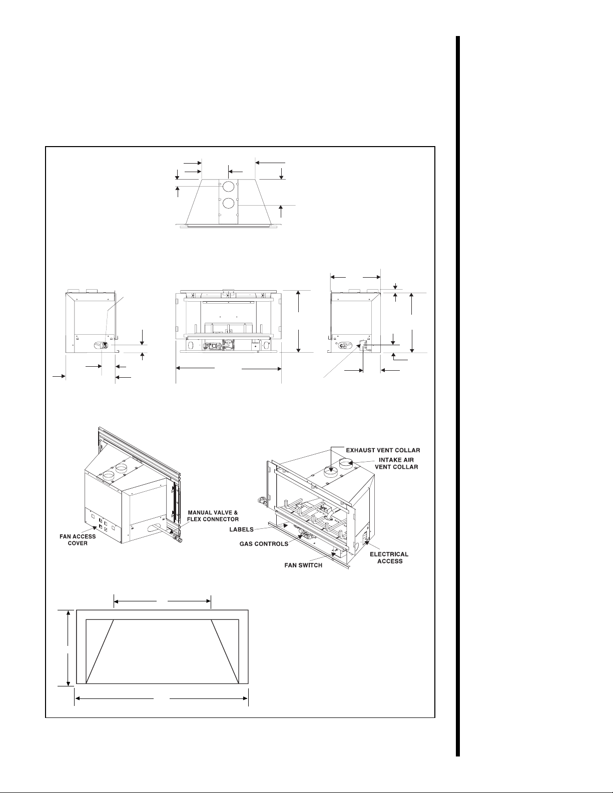
When planning a fireplace insert installation, its necessary to determine:
The vent system configuration to be used.
Gas supply piping.
Whether optional accessoriesdevices such as a wall switch, or remote
controlare desired.
GAS
LINE
3 3/16
(81mm)
4 7/8 (124mm)
14 5/8
(371mm)
2 1/8
(54mm)
7 1/4 (2)
(184mm)
28
(729mm)
11/16
14 1/2 (368mm)
7 1/8
(181mm)
(476mm)
18
3/4
ELECTRICAL
ACCESS
14
(355mm)
4
11/16
(119mm)
1
(25mm)
(457mm)
18
2
1/8
(54mm)
15
14
TOP VIEW
23
3/4
Figure 1. Diagram of the AT-ZC
MINIMUM FIREPLACE SIZE
FRONT WIDTH: 23 3/4” (603mm)
REAR WIDTH : 15” (572mm)
DEPTH : 14” (356mm)
HEIGHT : 20” (508mm)
*
NOTE: If exhaust collar on insert and fireplace damper
*
do not line up, add 4 inches (102mm) to minimum
fireplace height for bends in vent pipe.
4
Page 8
3
Installing the Insert
Step 1
Installing the
Vent System
Vent System Installation Precautions
Before starting installation of vent kits, the installer
should read these instructions and the Vent Kit
Instructions to ensure that a proper vent installation is
completed.
Consult your local Building Codes before beginning
the Installation.
WARNING
THIS GAS INSERT AND VENT
ASSEMBLY MUST BE VENTED
DIRECTLY TO THE OUTSIDE AND
MUST NEVER BE ATTACHED TO A
CHIMNEY SERVING A SEPARATE
SOLID FUEL BURNING APPLIANCE.
EACH GAS APPLIANCE MUST USE A
SEPARATE VENT SYSTEM. COMMON
VENT SYSTEMS ARE PROHIBITED.
Vent System Approvals
Table 1 and Figure 3 through 5 shows the vent
termination caps and systems approved for the use
with these models. Approved vent system
terminations are labeled for identification. 3-inch
diameter listed flexible aluminum or stainless steel
gas vent is used for both the incoming combustion air
and exhaust vent pipes. NO OTHER VENTING
SYSTEMS OR COMPONENTS MAY BE USED.
Detailed installation instructions are included with
each vent termination kit and should be used in
conjunction with this manual.
Horizontal Venting
The vent system on this model CANNOT be
terminated horizontally.
Vertical Venting
The vent pipes MUST be connected to the proper
collars on the unit AND the exhaust vent pipe MUST
be connected to the termination cap or the unit will not
operate. The combustion air vent pipe CAN be
connected to the termination cap or it can terminate
inside the chimney. The bottom opening of the
chimney must be sealed around the vent pipes if the
combustion air vent is NOT connected to the
termination cap. See Figures 3, 4 and 5.
NOTE: The minimum vertical rise (exhaust vent) is
14 feet and the maximum vertical rise is 50 feet.
These dimensions are measured from the starting
collars of the unit to the end of the last section of vent
pipe See dimension V in Figure 3.
5
Page 9

A vertical vent termination system installed on this
model will include one (1) length of 3-inch flexible vent
pipe for the combustion air, one (1) pipe-to-cap
adaptor, and one (1) SLK-991DA or SLK-980D Vertical
termination Cap.
NOTE: The damper of the masonry chimney may
need to be removed to allow installation of the flexiblevent pipe.
This fireplace has been altered to accommodate an
insert and should be inspected by a qualified person
prior to re-use as a conventional fireplace.
NOTE: The above label, located in the instruction
package, must be affixed to the existing fireplace prior
to installation of Model BAY-INS.
For zero clearance, factory built woodburning
fireplaces, the use of kit LINK-ZC-ADP, in place of the
standard square flashing, will allow you to mount the
adaptor and cap on metal pipe. Additionally, the use of
kit FLASH-DAMP will seal off the damper opening
when terminating the inlet air vent pipe just above the
damper. These two kits are recommended for zero
clearance, factory built woodburning fireplaces.
Connecting the Vent Pipe
Install the 3-inch flexible vent pipes down through the
chimney. Attach and secure the bottom ends of the
flex pipes to the starting collars on the unit with 3
sheetmetal screws on each collar. Slide the gas insert
into place, and position any excess flex vent pipe back
up into the chimney.
NOTE: Optional ZC-ADP Kit can be attached to the
top of the unit and will increase the depth of the units
starting collars if needed. See Figures 4 and 5.
Attach the pipe-to-cap adaptor to the termination cap
and the top of the flexible vent pipe and set the cap in
place at the top of the chimney. See Figures 3, 4 & 5.
6
Page 10

CAUTION
TO AVOID DOWNDRAFTS AND/OR COLD AIR
PROBLEMS, IT IS RECOMMENDED TO SEAL
OFF THE AREA BETWEEN THE TERMINATION
CAP AND THE TOP OF THE SOLID-FUEL
CHIMNEY OPENING INTO WHICH THE VENT
CAP HAS BEEN INSTALLED.
WHEN USING THE LINK-DV4-30 VENT SYSTEM,
IT IS REQUIRED TO SEAL AROUND THE
FLEXIBLE VENT PIPES IN THE DAMPER AREA.
SEE FIGURE 3. USE FIBERGLASS INSULATION
OR OTHER SUITABLE NON-COMBUSTIBLE
MATERIAL.
VENT SYSTEM APPROVALS
AT-ZC LINK-DV30
LINK-DV4-30
TABLE 1
WARNING: MAJOR U.S. BUILDING
CODES SPECIFY MINIMUM CHIMNEY
AND/OR VENT HEIGHT ABOVE THE
ROOF TOP. THESE MINIMUM HEIGHTS
ARE NECESSARY IN THE INTEREST OF
SAFETY. FIGURE 2 SHOWS MINIMUM
HEIGHTS, PROVIDED THE
TERMINATION CAP IS AT LEAST 8-FEET
FROM A VERTICAL WALL.
NOTE: This also pertains to vertical vent systems
installed on the outside of the building.
Termination
Cap
Roof Pitch H (min.) ft.
flat to 6/12 1.0
6/12 to 7/12 1.25
over 7/12 to 8/12 1.5
over 8/12 to 9/12 2.0
over 9/12 to 10/12 2.5
over 10/12 to 11/12 3.25
over 11/12 to 12/12 4.0
over 12/12 to 14/12 5.0
over 14/12 to 16/12 6.0
over 16/12 to 18/12 7.0
over 18/12 to 20/12 7.5
over 20/12 to 21/12 8.0
7
Figure 2. Minimum Height from Roof to Lowest
Discharge Opening
Page 11

TERMINATION CAP
ADAPTOR
EXHAUST VENT PIPE
V= 14FT. MINIMUM
50FT. MAXIMUM
WARNING: DO NOT BLOCK
PIPE END WITH INSULATION
OR ANY OTHER SEALING
MATERIAL.
This option shows
both exhaust and
inlet air vent pipes
attached the
adaptor.
Figure 3.
INLET AIR
VENT PIPE
WARNING
THE EXHAUST PIPE MUST ONLY BE
CONNECTED TO THE EXHAUST
STARTING COLLAR OF THE UNIT
AND THE CENTER COLLAR OF THE
TERMINATION CAP.
THE INLET AIR PIPE MUST ONLY BE
CONNECTED TO THE INLET AIR
COLLAR OF THE UNIT AND EITHER
ATTACHED TO THE INLET AIR
COLLAR OF THE TERMINATION CAP
OR TERMINATED IN THE CHIMNEY.
8
Page 12

Figure 4
EXHAUST
STARTING
COLLAR
INLET AIR
STARTING
COLLAR
9
Figure 5
Page 13

Step 2
Positioning,
Leveling, and
Securing the
Insert
1. Place the insert into position.
2. Level the insert from side to side and from front to
back.
If necessary use the legs included in the manual bag.
Screw the legs into the nuts installed in the bottom
rear of the insert. Turn legs in until insert is level.
Step 3
The Gas Control
Systems
WARNING
THIS UNIT IS NOT FOR USE WITH
SOLID FUEL.
The gas control systems used with this model is
Standing Pilot Ignition.
Standing Pilot Ignition System
This system includes millivolt control valve, standing
pilot, thermopile/thermocouple flame sensor, and
piezo ignitor.
WARNING
110-120 VAC MUST NEVER BE
CONNECTED TO A CONTROL VALVE IN
A MILLIVOLT SYSTEM.
STANDING PILOT
Figure 6. Gas Controls Systems
10
Page 14

Step 4
USE A WRENCH ON
SHUT-OFF VALVE WHEN
TIGHTENING GAS LINE.
USE A WRENCH ON
SHUT-OFF VALVE WHEN
TIGHTENING GAS LINE.
FLEX CONNECTOR
GAS VALVE
MANUAL SHUT-OFF
VALVE
MANUAL SHUT-OFF
VALVE
The Gas
Supply Line
NOTE: Have the gas supply line installed by a
qualified service technician in accordance with
all building codes.
NOTE: Before the first firing of the fireplace, the
gas supply line should be purged of any trapped
air.
NOTE: Consult local building codes to properly
size the gas supply line leading to the 1/2 inch
(13 mm) hook-up at the unit.
This gas fireplace is designed to accept a 1/2 inch
(13 mm) gas supply line.
To install the gas supply line:
A listed 1/2 inch (13 mm) manual shut-off valve and
a listed flexible gas connector are connected to the
3/8 inch inlet of the control valve.
A 1/8 inch (3 mm) N.P.T. plugged tapping, acces-
sible for test gauge connection, should be provided
for in the gas supply line leading to the units shutoff valve.
Locate the gas line access hole in the outer casing
of the insert.
Open the lower grille, insert the gas supply line
through the gas line hole, and connect it to the shutoff valve.
When attaching the pipe, support the control so that
the lines are not bent or torn.
After the gas line installation is complete, use a
soap solution to carefully check all gas connections
for leaks.
11
The gas line should be
installed by a qualified
service technician.
WARNING
DO NOT USE AN OPEN FLAME TO
CHECK FOR GAS LEAKS.
CONTROL
VALVE
Figure 7. Gas Supply Line
Page 15

Step 5
Gas Pressure
Requirements
Pressure requirements for Heat-N-Glo gas appliances
are shown in the table below.
Pressure Natural Gas Propane
Minimum 5.0 inches 11.0 inches
Inlet Pressure w.c. w.c.
Maximum Inlet 14.0 inches 14.0 inches
Gas Pressure w.c. w.c.
Manifold 3.5 inches 10.0 inches
Pressure w.c. w.c.
A one-eighth (1/8) inch (3 mm) N.P.T. plugged tapping is
provided on the outlet side of the gas control for a test
gauge connection to measure the manifold pressure. To
measure inlet pressure, provisions must be made to
attach a test gauge to a one-eighth (1/8) inch (3 mm)
N.P.T. plugged tapping immediately upstream of the gas
supply connection to the fireplace. On some models
there may be a tap for the manifold and inlet pressure
on the face of the valve. Use a small flat blade
screwdriver to open the needle valve tap. Position a
rubber hose over the tap to obtain the pressure reading.
Step 6
Wiring the
Fireplace
The fireplace and its individual shut-off valve must be
disconnected from the gas supply piping system during
any pressure testing of the system at test pressures in
excess of one-half (1/2) psig (3.5 kPa).
The fireplace must be isolated from the gas supply
piping system by closing its individual shut-off valve
during any pressure testing of the gas supply piping
system at test pressures equal to or less than one-half
(1/2) psig (3.5 kPa).
NOTE: Electrical wiring must be installed by a
licensed electrician.
DISCONNECT REMOTE CONTROLS IF YOU ARE
ABSENT FOR EXTENDED TIME PERIODS. THIS
WILL PREVENT ACCIDENTAL FIREPLACE
OPERATION.
For Standing Pilot Ignition Wiring
Appliance Requirements
This appliance DOES NOT require 110-120 VAC to
operate.
WARNING
DO NOT CONNECT 110-120 VAC TO THE
GAS CONTROL VALVE OR THE
APPLIANCE WILL MALFUNCTION AND
THE VALVE WILL BE DESTROYED.
12
Page 16

Optional Accessories
Optional fan and remote control kits require that 110120 VAC be supplied to the factory installed junction
box. Run the cord out the notch in the surround and
plug into a convenient outlet.
Remote Wall Switch
Position the remote wall switch in the desired position
on a wall. Run a maximum of 25 feet (7.8 m) or less
length of 18 A.W.G. minimum wire and connect it to
the fireplace valve pigtails.
WARNING
DO NOT CONNECT 110-120 VAC TO THE
REMOTE WALL SWITCH OR THE
CONTROL VALVE WILL BE
DESTROYED.
CAUTION
LABEL ALL WIRES PRIOR TO DISCONNECTION
WHEN SERVICING CONTROLS. WIRING
ERRORS CAN CAUSE IMPROPER AND
DANGEROUS OPERATION. VERIFY PROPER
OPERATION AFTER SERVICING.
13
Figure 8. Standing Pilot Ignition Wiring Diagram
Page 17

BLK
BLK
VARIABLE SPEED CONTROL
BLK
BLK
FAN WIRING DIAGRAM
JUNCTION BOX
BLK
NOTE: IF ANY OF THE ORIGINAL WIRE
NOTE: IF ANY OF THE ORIGINAL WIRE
AS SUPPLIED WITH THE APPLIANCE
AS SUPPLIED WITH THE APPLIANCE
MUST BE REPLACED, IT MUST BE
MUST BE REPLACED, IT MUST BE
REPLACED WITH TYPE 105 DEGREE C
REPLACED WITH TYPE 105 DEGREE C
RATED WIRE.
RATED WIRE.
BLOWER RECEPTACLE
BLK
TEMPERATURE
TEMPERATURE
SENSOR SWITCH
SENSOR SWITCH
FAN
BLK
JUNCTION
BOX
BLK
BLK
GROUND
110-120 VAC
GRN
WHT
BLK
WHT
BLOWER
WHT
TEMPERATURE
SENSOR SWITCH
SPEED CONTROL
(RHEOSTAT)
Figure 9. Fan Wiring Diagram
Step 7
Installing Logs
and Ember
Material
Positioning the Logs
If the gas logs have been factory installed they should
not need to be positioned.
If the logs have been packaged separately, refer to the
installation instructions that accompany the logs.
Save the log instructions with this manual.
If sooting occurs, the logs might need to be
repositioned slightly to avoid excessive flame
impingement.
Placing the Ember Material
Two separate bags of ember material are shipped
with this gas appliance:
The bag labeled Golden Ember (GE-93) is flame
The bag labeled Glowing Ember (050-721) is
To place the ember material:
Remove the trim door by lifting up and removing
colorant material.
standard glowing ember material.
from the unit.
Pull out and rotate the three glass release eye bolts
at the top of the glass.
14
Page 18

1. Lift the top trim door
up and out of the unit.
2. Pull out and rotate
glass release eye
bolts at the top edge
and remove the glass
door from the unit.
Remove the glass door from the unit.
Cover the top of the burner with a single layer of
ember material. Then sprinkle GE-93 on top of the
burner.
Save the remaining ember materials for use during
fireplace servicing.
Replace the glass door.
Reset the three glass eye bolts, be sure they are
securely latched.
Replace the trim door.
1. Place the ember
material onto the top
of the burner.
GLASS
DOOR
Figure 10. Glass Assembly
15
Figure 11. Placement of the Ember Material
Page 19

Step 8
Installing Trim
Surrounds
TRIM DOOR
Combustible materials MUST NEVER overlap onto the
front face.
WARNING INSERT,
WHEN FINISHING THE FIREPLACE
NEVER OBSTRUCT OR MODIFY THE
AIR INLET/OUTLET GRILLES ON THE INSERT IN
ANY MANNER.
For Masonry Fireplace Installation
FIREBOX
SURROUND
ON/OFF
SWITCH
Note: See
accessory parts
page for trim door
and surround
options.
Figure 12
SURROUND
For Zero Clearance Fireplace Installation
TRIM DOOR
LOW VOLT AGE
WIRES
NOTE: REMOVE FRONT TRIM DOOR AND GLASS
DOOR ASSEMBLIES FROM THE INSERT BEFORE
SURROUND INSTALLATION.
1. Find the coiled low voltage wires and ON/OFF switch
attached to outer right side of the insert. See Figure 12.
2. Disconnect the ON/OFF switch from the low voltage wire
leads, and insert the short wires of the ON/OFF switch
through the hole at the upper right corner of the surround
and push the back of the switch through the hole - it will be
retained in the hole.
16
Page 20

3. Run the low voltage lead wires up the back of the right
side of the surround and secure them with the three
wire ties found there. Re-connect the low voltage wires
to the short wires of the ON/OFF switch.
4. Position surround on face of unit by hooking surround
behind top ledge on unit. Then push flush on unit and
secure by bending three holding tabs downward.
NOTE: PLACE THE THREE INSULATION PIECES
INTO THE CAVITIES AT THE BACK OF THE
SURROUND BEFORE POSITIONING THE INSERT
INTO THE FACTORY-BUILT OR MASONRY
FIREPLACE. THIS INSULATION WILL HELP SEAL
FOR COLD AIR LEAKS.
MANTEL
12” MAX.
Figure 13
12” MAX.
TOP OF UNIT
17
Figure 13 shows the minimum vertical and corresponding
maximum horizontal dimensions of mantels or other
combustible projections above the gas fireplace.
Page 21

Step 9
Before Lighting
the Appliance
Before lighting the appliance, be sure to do the
following:
Review safety warnings and cautions
Read the Safety and Warning Information section
at the beginning of this Installers Guide.
Double-check for gas leaks
Before lighting the appliance, double-check the unit
for possible gas leaks.
Double-check vent terminations and front grilles
for obstructions.
Before lighting the appliance, double-check the unit
for possible obstructions that could be blocking the
vent terminations or the front grilles.
Double-check for faulty components
Any component that is found to be faulty MUST BE
replaced with an approved component. Tampering
with the appliance components is DANGEROUS
and voids all warranties.
A small amount of air will be in the gas supply lines.
When first lighting the appliance, it will take a few
minutes for the lines to purge themselves of this air.
Once the purging is complete, the appliance will light
and will operate normally.
Step 10
Lighting the
Appliance
After the
After the
Installation
Installation
Subsequent lightings of the appliance will not require
this purging of air from the gas supply lines, unless
the gas valve has been turned to the OFF
position, in which case the air would have to be
purged.
Youve reviewed all safety warnings, youve checked
the appliance for gas leaks, you know the vent system
is unobstructed, and youve checked for faulty
components. Now youre ready to light the appliance.
WARNING
PLEASE REFER TO THE USERS
MANUAL FOR ALL CAUTIONS, SAFETY,
AND WARNING INFORMATION
PERTAINING TO THE LIGHTING AND
OPERATION OF THE APPLIANCE.
LEAVE THIS INSTALLATION MANUAL
WITH THE APPLIANCE FOR FUTURE
REFERENCE.
18
Page 22

Appliance
Maintenance
Although the frequency of servicing and maintenance
will depend on use and the type of installation, you
should have a qualified service technician perform an
appliance check-up at the beginning of each heating
season. See the table below for specific guidelines
regarding each maintenance task.
4
Maintaining
and
Servicing
Your
Appliance
IMPORTANT
Type of
Fireplace Fireplace Maintenance Task To
Maintenance Frequency By Be Completed
Replacing Once annually, Qualified Brush away loose ember material near
Old Ember during the Service the burner. Replace old ember
Material annual check-up Technician material with new dime-size and -shape
Cleaning Once annually Qualified Brush or vacuum the control
Burner Service compartment, fireplace logs, and
& Controls Technician burner areas surrounding the logs.
Checking Periodically Qualified Make a visual check of your fireplaces
Flame Service flame patterns. Make sure the flames
Patterns, Technician/ are steadynot lifting or floating. See
Flame Height Owner the picture in Figure 14. The flame
TURN OFF THE GAS BEFORE SERVICING
YOUR APPLIANCE.
pieces of Golden Ember (GE-93) and
Glowing Ember (050-721). New ember
material should be placed alternately on
top of the burnera layer of Golden
Ember, a layer of Glowing Ember,
and so on. Save the remaining ember
material and repeat this procedure at
your next servicing. For more
information, see Placing Ember
Material in the INSTALLERS GUIDE.
sensor(DSI) or thermopile/thermocouple
(standing pilot) tips should be covered
with flame. See the picture in Figure15.
19
Checking Before initial use Qualified Inspect the external vent cap on a
Vent System and at least Service regular basis to ensure that no debris is
annually thereafter, Technician/ interfering with the flow of air. Inspect
more frequently Owner venting system for proper function.
if possible
Cleaning As necessary Homeowner Clean as necessary, particularly after
Glass Door adding new ember (flame colorant)
material. Film deposits on the inside of
the glass door should be cleaned off
using a household glass cleaner.
NOTE: DO NOT handle or attempt to
clean the door when it is hot and
DO NOT use abrasive cleaners.
Page 23

MAKE SURE THE FLAMES
ARE STEADYNOT
LIFTING OR FLOATING.
Figure 14. Burner Flame Patterns
STANDING PILOT
Figure 15. Pilot/Ignitor Flame Patterns
3/8" (10 mm)
20
Page 24

5
Replacement
Parts and
Accessories
All parts listed in this INSTALLERS GUIDE may be
ordered from an authorized dealer. When requesting
service or replacement parts for your fireplace, please
provide the model number and the serial number.
Standing Pilot Only
PART PART DESCRIPTION PAR T NUMBER
Valve LP SRV60–523
Valve NG SRV60–522
Piezo Ignitor SRV418-513
Thermopile SRV60–512
Thermocouple SRV446-511
Pilot Orifice LP SRV446–517
Pilot Orifice NG SRV446–505
Pilot Assembly LP SRV485-511A
Pilot Assembly NG SRV485-510A
Pilot Tube SRV446-301
Burner Tube SRV485-300
21
Page 25

Standing Pilot Continued
PART PART DESCRIPTION P ART NUMBER
Burner SRV485-275A
Burner Orifice NG SR V60-800
Burner Orifice LP SRV60-801
Rotory Switch SR V436 -525A
Glass Door Assembly GLA -A TZC
Grate Assembly SRV485-360A
Refractory SR V485-700
22
Page 26

Standing Pilot (Cont.)
PART PART DESCRIPTION
Log #1 SRV 447-701
Log #2 SRV446-703
Log #3 SRV446-702
Log #4 SRV485-702
PART
NUMBER
23
Accessories
ACCE SSORY PART DESCRIPTION PART NUMBER
Logs Complete Set Logs-ATZC
Remote Control Kit RCH-09A
RC-SMART
RC-SMART
SMART-STAT
SMART-STAT
RC-MLT
RC-MLT
Wall Switch Kit
- Off White WSK -2 1
- White WSK-21-W
Page 27

Accessories - (Continued)
ZC-3624-3
ZC-4028-3
ZC-3627-4
ZC-3627-3
DF-ZC Trim Door
DF-ZC-Carch Trim Door
24
Page 28

Accessories - (Continued)
DF-ZC32- T rim Door
DF-ZC36- T rim Door
DF-ZC32-Carch T rim Door
DF-ZC36- Carch Door
25
 Loading...