

Page 1

AK-TV OUTSIDE AIR KIT
- Installation and Operation Instructions -
The AK-TV Air Kit is used to bring in outside make-up and
combustion air to solid wood fuel fireplaces and gas fireplaces. Check the fireplace instructions.
The air drawn into the fire chamber from outside the home or
unheated area helps relieve the demand for combustion air
being drawn into the fireplace from inside the home.
CONTENTS OF SHIPPING CARTON
Compare contents of the shipping of the carton in Figure 1
with actual parts received. If any parts are missing or damaged, contact your dealer before starting installation.
NOTE: 4-inch Class 1 ducting material or metal duct
may be used with AK-TV.
WARNING: Six inch duct must be used for inst allation
of solid fuel fireplaces into a mobile home. (For installation
in the state of New York, only aluminum non-combustible
flexible or type "0" metal ducting is permissible).
Duct T ermination
Screws (8) Flex
Side Collar
(2)
Duct
INSTALLATION PRECAUTIONS
CAUTION
Sharp Edges
• Wear protective gloves
and safety glasses
during installation.
The duct termination should be located so it is exposed to
an out-of-doors opening at least 100 square inches. If the
duct termination must be located in a crawl space or basement, be sure the termination area has 100 square inches
of ventilation opening to outside air .
The duct termination must be located so it does not compete for air flow with exhaust fans, gas vent hoods or other
air consuming devices or appliances. It must not be obstructed by rafters, insulating materials, or other obstructions. The less restrictive the air supply , the better the AKTV will perform.
W ARNING
Asphyxiation Risk.
Fire Risk.
Do NOT draw outside combustion air from:
• Wall, floor or ceiling cavity.
• Enclosed space such as an attic or garage.
• Close proximity to exhaust vents or chimneys.
Fumes or odor may result.
Plastic Tie Strap - (4)
Handle
Damper
Assembly
FIGURE 1. CARTON CONTENTS
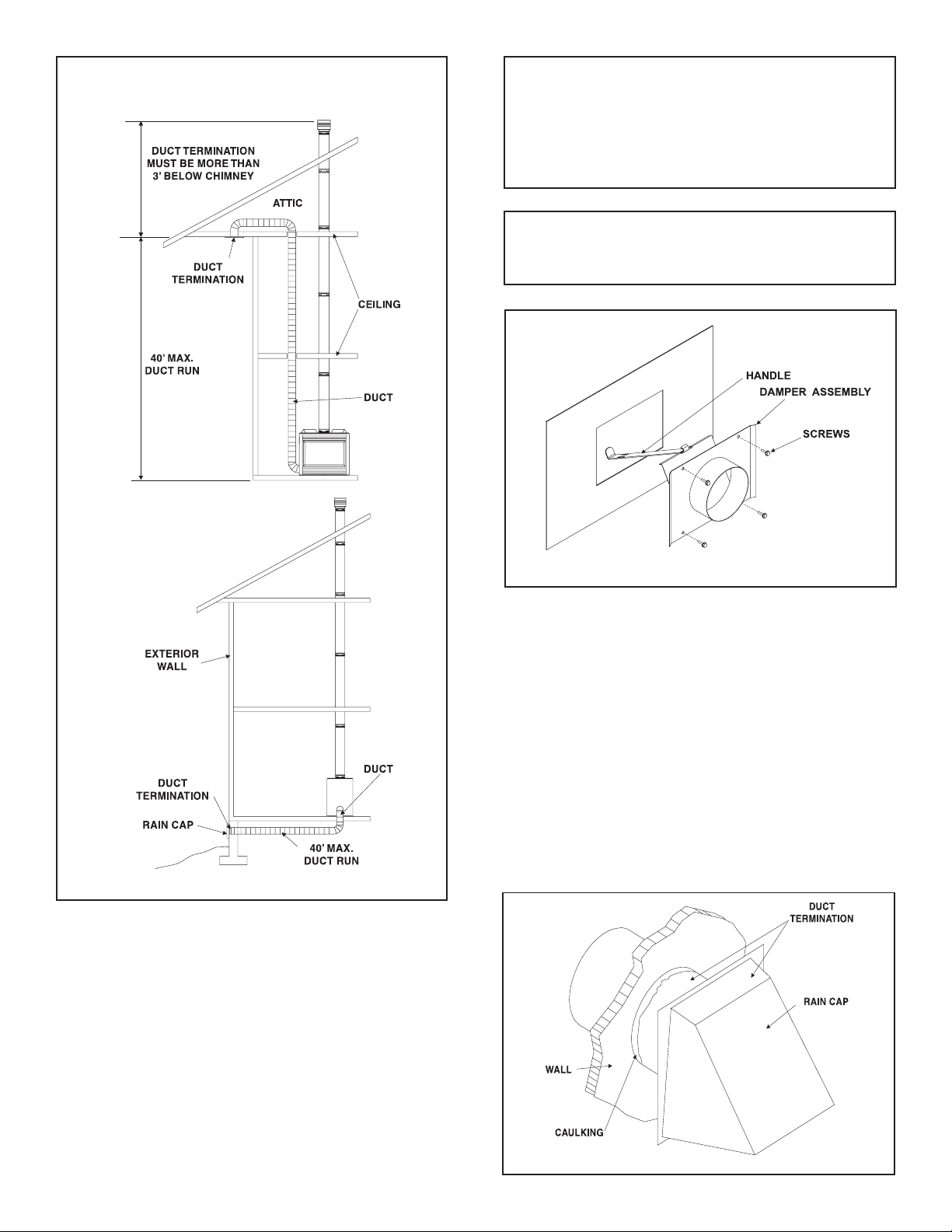
INSTALLATION INSTRUCTIONS
Determine the location of the fireplace as described in the
fireplace installation manual. Then plan the location of the
duct termination and the route of the duct run between the
fireplace and the duct termination.
The duct run must be limited to a maximum distance of 40
feet from the fireplace pipe collar to duct termination. This
will provide the least restriction to air flow. No more that
four 900 elbows can be used. The duct run may be horizontal, vertical inclined or any combination for these for all
models unless noted in the fireplace manual. Vertical duct
runs must be at least three (3) feet below the fireplace
chimney flue exit. See Figure 2.
Printed in U.S.A. Copyright 2004
Hearth & Home Technologies Inc.
20802 Kensington Boulevard, Lakeville, MN 55044
1
197-900B 12/04
Page 2
SOFFIT TERMINA TION
NOTE: Some gas fireplaces may have a round cutout
for the outside air attachment. For these models, the
DAMPER ASSEMBLY should be positioned from the
inside of the fireplace controls compartment, with the
collar protruding through the round cutout. Secure in
the same manner.
EXTERIOR WALL
TERMINATION
NOTE: If using the AK-TV on an SL Series gas fireplace, rotate the damper assembly 90
0
counterclock-
wise so the door opens from the left to right.
FIGURE 3
3. Slide the duct over the damper assembly collar and attach the duct to the collar using the plastic tie straps or
three (3) screws (screws not provided). Continue attaching the ducting together using three (3) screws at
each joint until you have installed sufficient duct to arrive at the desired location for the outside air source.
FIGURE 2
Gas Burning Fireplaces:
1. Remove and discard the outside air coverplate (or knockout) located at the side or bottom of the fireplace. Use
care not to rub against the sharp edges of this opening
to avoid cuts. Some appliances may not have a cover
plate.
2. Insert the narrow portion of the HANDLE into the slot on
the DAMPER ASSEMBLY . Orient the DAMPER ASSEMBL Y so the handle extends off the top and into the fireplace controls compartment. Secure in place over the
opening on the fireplace using the provided screws (4). See
Figure 3.
4. Install the duct termination assembly from the outside
of the home. Cut a hole in the desired location, caulk
around the hole, and slide the assembly through the
opening from outside the home. Secure in place with
screws. The assembly should be caulked around its perimeter to assure a tight seal. The opening should be
positioned downward. See Figure 4.
FIGURE 4
2
Page 3

Wood Burning Fireplaces:
5. Remove the 4 screws holding the cover plate over the
outside air hole in the side of the fireplace's outer skin.
Attach the 2 foot section of flex duct to one of the side
collars with a plastic tie strap. Insert the flex duct through
the outer skin all the way to the collar. Place the second
side collar, (flat side towards the unit) against the other
collar and using the screws previously removed, secure
both collars to the fireplace outer skin.
Follow previous instructions to run air duct to inlet tube
assembly.
Open lower grille and attach the flex duct to the duct
collar on the underside of the fire chamber base. Secure
by using a plastic tie strap. See Figure 5.
NOTE: The outside air damper control for models EM41 and EM-48 is factory installed and is located behind the lower grill in the middle of the unit. To open
the damper, pull the control rod forward and lef t until
the damper locks into open position. The damper MUST
be open for the unit to operate properly . The damper
assembly provided with this kit will not be used with
these models.
6. The AK-TV Outside Air Kit is now installed and ready for
use.
OPERA TION PRECAUTIONS
AND INSTRUCTIONS
For all solid wood fuel fireplaces:
When operating with glass doors, open the doors and close
the fireplace outside air damper so your fire will be started
using room air. Af ter the fire is well started, you may open
the outside air control and close the doors to provide air to
the fire.
For gas fireplaces:
When lighting your gas fireplace, you MUST always first
open the combustion air damper for the unit to operate and
the glass doors MUST be in place. To open pull handle
towards the center of the fireplace.
Periodically inspect the duct termination assembly for any
blockage. Correct if necessary .
For maximum benefit and efficient usage, refer to operating
instructions in owner's manual.
FIGURE 5 Duct attachment on wood burning
fireplaces
Replacement parts and service may be obtained through
your dealer.
3
 Loading...