

Heat-Flo 115-HO-C, 85-XHO, 80-HO-C, 115-XHO Installation, Operating And Service Instructions
Page 1
Page 2

Page 3
Table of Contents
General Information i-ii
Pre-Installation Considerations 1-8
Dimensions and Capacities 2, 3
Piping 6-10
Electrical 11-13
Operation 11
Important Scalding Information 11, 14
Maintenance 15, 17
Troubleshooting 18
Boiler Supply Ratings 19
Replacement Parts 20
Limited Warranty 21, 22
Page 4

IMPORTANT INFORMATION – READ CAREFULLY
NOTE: The equipment shall be installed in accordance with those installation regulations required in the area where
the installation is to be made. These regulations shall be carefully followed in all cases. Authorities having jurisdiction
shall be consulted before the installations are made.
All wiring on water heaters must be in accordance with the National Electrical Code (latest edition) and/or local
regulations in the US, and in accordance with the Canadian Electrical Code (latest edition) and/or local regulations
in Canada.
WARNING
Improper installation, adjustment, alteration, service or maintenance can cause property damage, personal injury,
or loss of life. Read and understand the entire manual before attempting installation, start-up, operation, or service.
Installation and service must be performed only by an experienced, skilled installer or service agency.
This water heater contains very hot water under high pressure. Do not unscrew any pipe fittings or attempt to
disconnect any components of this water heater without positively assuring that the water is cool and has no
pressure. Always wear protective clothing and equipment when installing, starting up or servicing this water heater
to prevent scalding injuries. Do not rely on the pressure and temperature gauges to determine the temperature and
pressure of the water heater. This water heater contains components that become very hot when the boiler is
operating. Do not touch any components unless they are cool.
Failure to follow all instructions in the proper order can cause personal injury or death. Read all instructions,
including all those contained in component manufacturers’ manuals before installing, starting up, operating,
maintaining, or servicing the water heater.
CAUTION
To reduce the risk of excessive pressures and temperatures in this water heater, install temperature and pressure
protective equipment required by local codes but no less than a combination temperature relief valve certified by a
nationally recognized testing laboratory that maintains periodic inspection of production of listed equipment or
materials, as meeting the requirements for Relief Valves and Automatic Shutoff Devices for Hot Water Supply
Systems, ANSI Z21.22-latest edition. This valve must be marked with a maximum set pressure not to exceed the
marked working pressure of the water heater. Install the valve into an opening provide and marked for this purpose
in the water heater, and orient it or provide tubing so that any discharge from the valve will exit only within 6 inches
above, or at any distance below, the structural floor, and cannot contact any live electrical part. The discharge
opening must not be blocked or reduced in size under any circumstances.
These water heaters with single-wall stainless steel heat exchangers meet the Uniform Plumbing Code for
installation in potable water systems provided that:
The boiler water, including additives, is practically non-toxic, having a toxicity rating of class 1 as listed in
Clinical Toxicology of Commercial Products, latest edition.
The boiler water pressure is limited to maximum 30 psig by an approved safety or relief valve.
The heat transfer medium is potable water or contains only substances that are recognized as safe by the U.S.
Food and Drug Administration. (FDA)
The pressure of the heat transfer medium is maintained less than the normal minimum operating pressure of
the potable water system.
The maximum boiler water supply temperature to the indirect heat exchanger must not exceed 240 deg. F
(115 deg. C).
Improper water quality will reduce the life of the water heater. Hard water, sediment, high or low PH and high levels
of chlorides in the domestic water should be avoided. Be sure that PH levels fall between 6 and 8 and dissolved
chlorides are less than 100 ppm. A filter must be used where sediment is greater than 5 microns in size in the water
supplied to the unit. A water softening system is recommended for areas with hard water. In cases where water
quality is unknown, a qualified water treatment expert should be consulted.
NOTICE: Damage to tanks caused by improper water quality is not covered under the warranty.
Heat-Flo, Inc.| Indirect-Fired Water Heaters Page| i
Page 5

DANGER
DO NOT store or use gasoline or other flammable vapors or liquids in the vicinity of this or any other appliance. If
you smell gas vapors, DO NOT try to operate any appliance - DO NOT touch any electrical switch or use any phone
in the building. Immediately, call the gas supplier from a remotely located phone. Follow the gas supplier’s
instructions or if the supplier is unavailable, contact the fire department. Do not operate any appliance until the
leakage is corrected.
DANGER
This water heater is supplied with an adjustable thermostat to control the water temperature. Hot water
temperatures required for automatic dishwashers and laundry use can cause scald burns resulting in serious
personal injury and/or death. The temperature at which injury occurs varies with the person’s age and the time of
exposure. The slower response time of disabled persons increases the hazard to them. NEVER allow small children
to use a hot water tap or to draw their own bath water. NEVER leave a child or disabled person unattended in a
bathtub or a shower.
IMPORTANT SAFETY INSTRUCTIONS
READ ALL INSTRUCTIONS BEFORE USING THIS WATER HEATER.
WARNING – When using electrical appliances, safety precautions should be taken to reduce the
risks of fire, electric shock, and injury. These precautions include the following:
This water heater must be grounded. Connect only to a properly grounded outlet. See
“GROUNDING INSTRUCTIONS” found in Section IV.
Install or locate this water heater only in accordance with the provided installation
instructions.
Use this water heater only for its intended use as described in this manual.
Do not use an extension cord set with this water heater. If no outlet is available adjacent
to the water heater, contact a qualified electrician to have one properly installed.
As with any appliance, close supervision is necessary when used by children.
Do not operate this water heater if it has a damaged cord or plug, if it is not working
properly, or if it has been damaged or dropped.
Your water heater should be installed and serviced only by qualified personnel. Contact
nearest authorized service facility for examination, repair, or adjustment.
Heat-Flo, Inc.| Indirect-Fired Water Heaters Page| ii
SAVE THESE INSTRUCTIONS
Page 6

Pre-installation Considerations
Inspect shipment carefully for signs of damage. All equipment is carefully inspected and packed.
Heat-Flo’s responsibility ceases upon delivery of the water heater to the carrier in good condition.
Any claims for damage or shortage must be filed immediately against the carrier by the
consignee. No claims for variances or shortages will be allowed by the Manufacturer, unless they
are presented within sixty days after receipt of the equipment.
Installation must conform to the requirements of the authority having jurisdiction. In the absence
of such requirements, installation must conform to the National Plumbing Code and the National
Electrical Code ANSI/NFPA No. 70 (current edition).
IMPORTANT CONSIDERATIONS BEFORE INSTALLATION
1. Water heater sizing:
Choose the water heater model based on the expected water usage for the given site.
The average residence with one shower or more will require a Model 40 or larger. The
Model 30 should only be considered for residences with minimal water demand, or for
commercial applications without showers.
Factors that increase water demand dramatically include high flow shower heads, hot
tubs, and the use of more than one shower at a time. Increase the tank size if these factors
are present. Consult ASHRAE sizing guides and other references.
Dimensions, weights, ratings, and capacities are outlined in Tables 1, and 2 (Pg. 2).
2. Boiler sizing:
The water heater will provide the rated performance only if it is used with a boiler with a
heating capacity of at least as much as the capacity ratings in Table 2. If the boiler has
less capacity, the water heating output will be reduced. To determine performance with
other boiler outputs, refer to the expanded capacity tables at www.heat-flo.com.
NOTICE
If the boiler takes longer to heat up from a cold start, hot water shortage may occur.
The maximum heat transfers through the coil (heat input) of the water heaters at 240 deg. F boiler supply
temperature and 210 deg. F potable water temperature are as follows:
Models 30 – 115 single coil units and models 60-D, 80-D, and 115-D dual coil units are less than
96,000 BTU/HR.
Models 80-HO, 115-HO, 80-HO-C, and 115-HO-C high output units are less than 84,000 BTU/HR.
Models 85-XHO and 115-XHO, the extra high output series, are less than 175,000 BTU/HR.
Potable water temperature is limited to below 210 deg. F and nominal water containing capacity is below
120 gallons for all indirect models.
Accordingly, per Part HLW-101.2, Section IV of the ASME Boiler and Pressure Vessel Code, all Heat-Flo
indirect water heater products are exempt from compliance with the code.
Heat-Flo, Inc.| Indirect-Fired Water Heaters Page| 1
Check with local codes for applicability.
Page 7
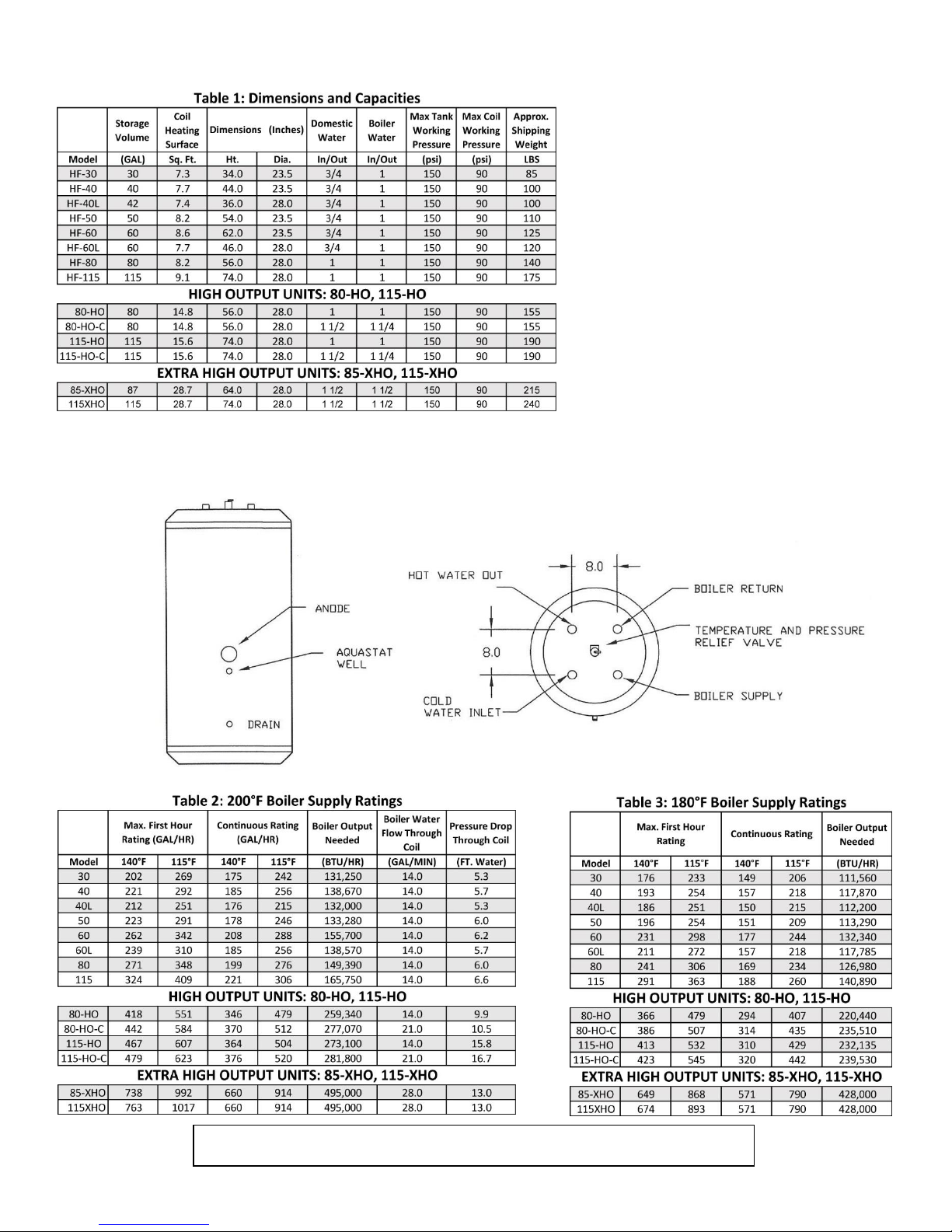
NOTE: All ratings are based on a 50° F. cold water inlet. For other boiler supply temperatures, see
additional tables on the website (www.heat-flo.com).
STANDARD AND HO UNITS
Heat-Flo, Inc.| Indirect-Fired Water Heaters Page| 2
Page 8
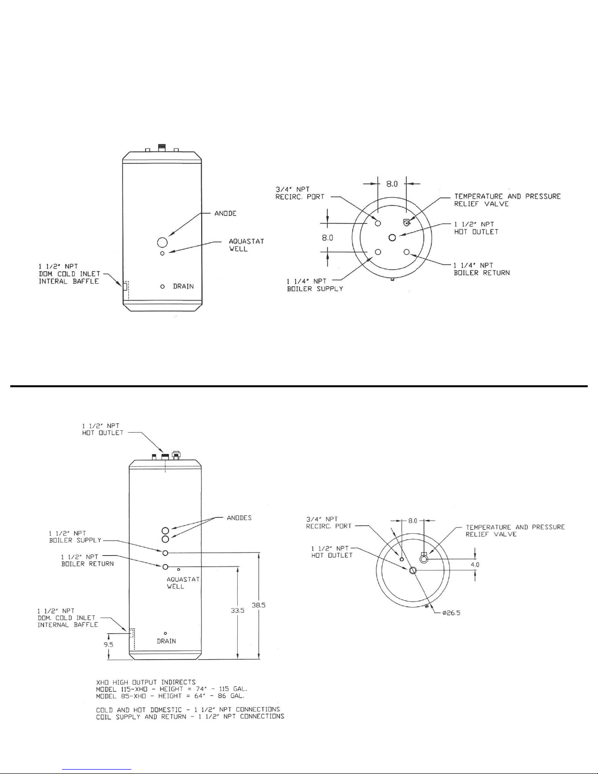
HO-C UNITS
XHO EXTRA HIGH OUTPUT UNITS
Heat-Flo, Inc.| Indirect-Fired Water Heaters Page| 3
Page 9

3. Circulator sizing:
Refer to Table 2 (Pg. 2) for the flow through the water heater coil and the pressure drop.
Calculate the pressure drop across all piping and fittings connected to the water heater
zone. Be sure to include all zone valves, check valves, and shut-off valves. It is
recommended that the water heater zone be piped with 1” pipe around the entire loop
on typical residential sites and with 1-1/4” and 1-1/2” pipes on high output units used on
commercial sites.
SYSTEM ZONE CONTROL
The water heater must be installed as a separate zone from the space heating system. The water
heating zone’s piping and circulator must be sized for the minimum flow rate with all the zones
in use and a maximum flow with only the water heater in use. The best method is to use a
separate circulator for the water heater.
The three most common systems are:
1. Zone Circulators- The space heating zones use a circulator for each zone, and the water
heater is controlled with an additional circulator.
2. Hybrid System- The space heating zones use zone valves for each zone, and the water
heater is controlled with an additional circulator.
3. Zone Valves – The space heating zones use zone valves for each zone, and the water
heater is controlled with an additional zone valve. Select a valve with a low pressure
drop, and assure minimum flow with adequate pipe sizing.
PRIORITY OR NON-PRIORITY FOR HOT WATER
Option 1: Priority
The demand for space heating is interrupted until the hot water demand is satisfied. This option
provides the maximum delivery of hot water.
Priority is recommended when:
a. The boiler output is less than 100,000 Btu per hour. Or,
b. The boiler output required to satisfy the hot water demand is more than 50% of the
boiler output needed to satisfy the space heating demand. Or,
c. When an interruption in space heating can be tolerated during long domestic hot water
draws.
In most cases the delay in space heating will not be noticed because of the rapid recovery of the
water heater. It must be recognized however that certain water heater malfunctions, such as a
failed thermostat or circulator, could delay space heating indefinitely.
Heat-Flo, Inc.| Indirect-Fired Water Heaters Page| 4
Page 10

Option 2: Non-Priority:
The boiler output is divided between space heating and water heating. Heating of domestic hot
water can be reduced during simultaneous space and water heating demands. The amount of
reduction depends on the boiler output, the number of space heating zones calling, and the
amount of boiler water flow split between the space heating and zones and the water heater
zone.
LOCATING THE WATER HEATER
The water heater should be located in an area where water leakage from the tank or connections
will not result in damage to areas adjacent to the water heater or to lower floors of the structure.
When such a location cannot be avoided, a suitable drain pan must be installed under the water
heater, and the drain pan must be connected to a drain. The drain pan depth must be suitable
for draining and collecting water. The piping to drain must be at least 3/4” diameter and be
pitched for proper drainage.
The water heater should be installed as close to the boiler as is practical for easy access for
service. The unit is designed for installation on combustible flooring and in alcoves, closets, etc.
The minimum clearances from combustible surfaces are:
Bottom 0”
Left, Right, and Rear Sides 1”
Front 1”
Top 6”
The minimum clearances for service are:
Bottom 0”
Left, Right, and Rear Sides 3”
Front 30”
Top 6”
ADDITIONAL RECOMMENDED COMPONENTS
1. Shut-Off Valves: Allows the isolation of the water heater from the boiler system during
service.
2. Unions: Allows for easy locating or removal.
3. Vacuum Breaker: Protects the water heater from collapse if a hot tank is valved off to
service other components in the system.
4. Thermal expansion tank. If the water heater is installed in a closed water supply
system, such as a system having a back flow preventer, a check valve, or a pressure
reducing valve in the cold water supply line, the installation of a thermal expansion
tank is required.
Heat-Flo, Inc.| Indirect-Fired Water Heaters Page| 5
Page 11
REMOVING THE EXISTING DOMESTIC WATER HEATING SYSTEM
External Tankless Heater
Disconnect all lines to the boiler and plug the boiler fittings. Disconnect the external
heater from the boiler piping, and the domestic piping systems.
Internal Tankless Heaters
Disconnect the domestic piping. Do not plug the cold water or the hot water fittings in
the internal tankless coil. Leave the coil in the boiler with the cold and hot water fittings
open to prevent pressure build-up in the coil.
NOTICE
For California installation this water heater must be braced, anchored, or strapped to
avoid falling or moving during an earthquake. See instructions for correct installation
procedures. Instructions may be obtained from California Office of the State Architect.
Water Quality
Improper water quality will reduce the expected life of the water heater. Hard water, sediment,
high or low Ph, and high levels of chlorides in the domestic water should be avoided. Sediment
and hard water will eventually coat the heating coil inside the water heater and reduce the rate
of hot water production and may eventually cause a failure. High or low Ph and/or high chloride
concentrations will cause corrosion and eventually failure. A filter is strongly recommended
where sediment is present in the water. A water softening system is recommended for areas with
hard water. In an area where the water quality is not known, a water quality test should be
performed.
WARNING:
Do not operate the Heat-Flo water heaters in areas where the Ph is above 8.0 or below 6.0,
and/or with chloride concentrations greater than 100 parts per million (ppm). Heat-Flo’s
standard warranty does not cover problems caused by improper water Ph or excessive levels of
chlorides.
NOTICE
Damage to tanks caused by improper water quality is not covered under the warranty.
PIPING
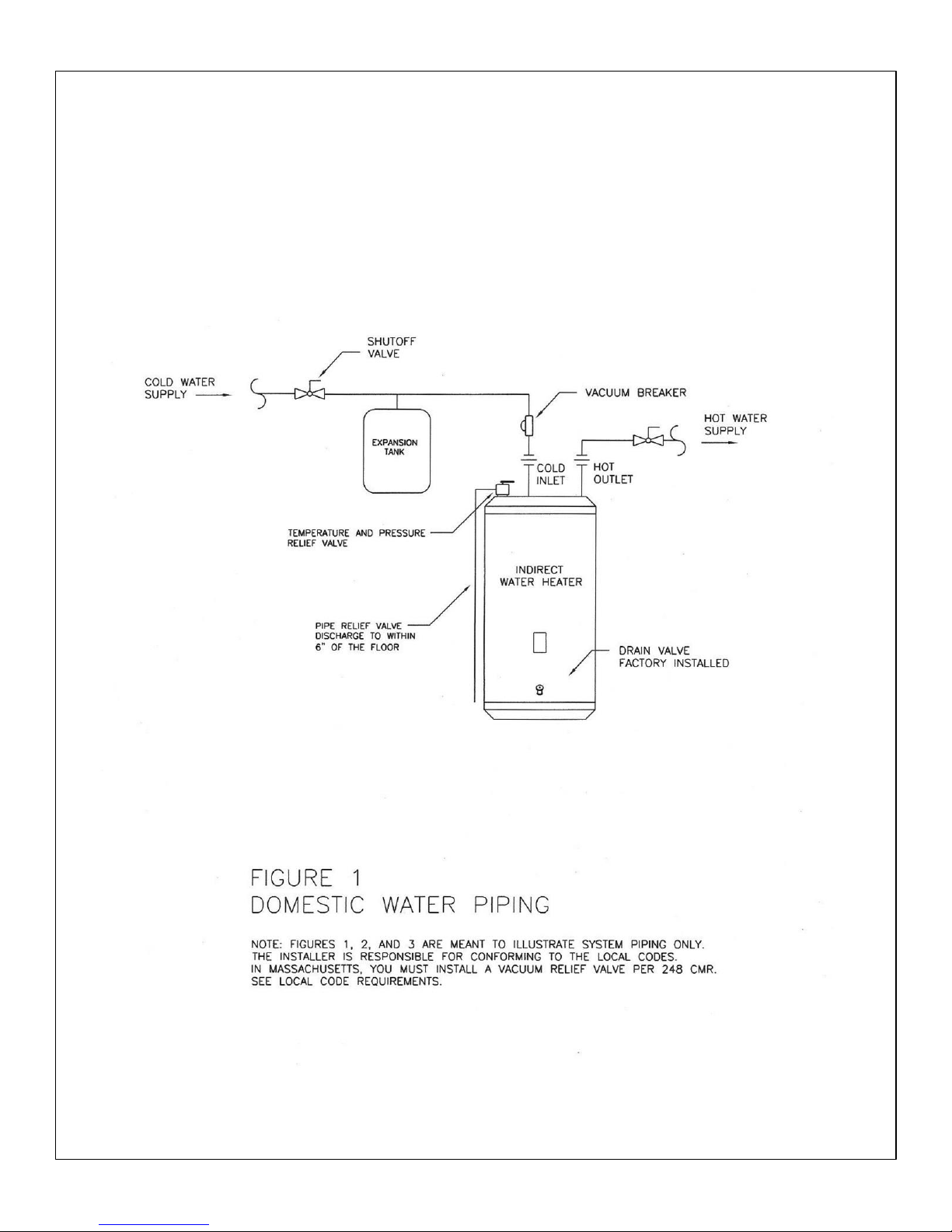
DOMESTIC WATER PIPING (See Figure 1, Pg. 9)
1. Drain the domestic water system.
Shut off the cold water supply at the main shutoff valve.
Open one or more faucets to relieve the pressure.
Open the system drain, leaving the faucets open.
Heat-Flo, Inc.| Indirect-Fired Water Heaters Page| 6
Page 12
2. Position the water heater in its final location
3. Connect the cold water supply piping.
Install piping onto cold inlet connection.
Connect to cold water supply connection using a union, a heat trap, a shut-off valve, a
vacuum breaker, an expansion tank (where required), and a filter (recommended to
prevent sediment buildup).
NOTICE
If installing on a city supply, a properly sized thermal expansion tank is required and
should be installed in accordance with the product installation manual.
If a water heater is installed in a closed water supply system, such as one having a
backflow preventer in the cold water supply, a check valve in the cold water supply, or a
pressure reducing valve in the cold water supply means shall be provided to control
thermal expansion.
The appliance, when installed, must be grounded in accordance with the local codes, or
in the absence of local codes, with the National Electrical Code, ANSI/NFPA 70.
WARNING
If this product is connected to a cold water supply line that has a check valve, a backflow
preventer, a pressure reducing valve, or a check valve in the water meter, it is a
requirement that a properly sized thermal expansion tank be installed in the cold water
inlet line. There will be no warranty on applications where there is no pressure control.
4. Connect the domestic hot water piping.
Install piping onto hot water supply connection using a union, a heat trap, and a shut
off valve.
Pipe the relief valve discharge so that the discharge from the valve will exit only within
6 inches above, or at any distance below, the structural floor and so that it cannot
contact any live electrical part. The discharge opening must not be blocked or reduced
in size under any circumstances.
WARNING
Install a discharge line so that water discharged from the temperature and pressure relief
valve will exit within six (6) inches above, or any distance below, the structural floor and
cannot contact any live electrical part. The discharge line is to be installed to allow for
complete drainage of both the temperature and pressure relief valve and the discharge
line. The discharge opening must not be subjected to blockage or freezing.
DO NOT thread, plug, or cap the discharge line. It is recommended that a minimum
clearance of four (4) inches be provided on the side of the water heater for servicing and
maintenance of the combination temperature and pressure relief valve.
Do not place a valve between the combination temperature and pressure relief valve
and the tank!
Heat-Flo, Inc.| Indirect-Fired Water Heaters Page| 7
Page 13

5. Fill the water heater.
Open all faucets to allow air to purge from the tank and piping. Remove screens on
faucets.
Open domestic hot water shut-off valve.
Open cold water inlet shut-off valve.
Purge all of the air from the domestic water system. Allow water to run so the tank is
completely purged of any debris. Run the water long enough to change at least five tank
volume changes.
Close all faucets. Reinstall all of the screens in the faucets.
Check the system for leaks. Repair as required.
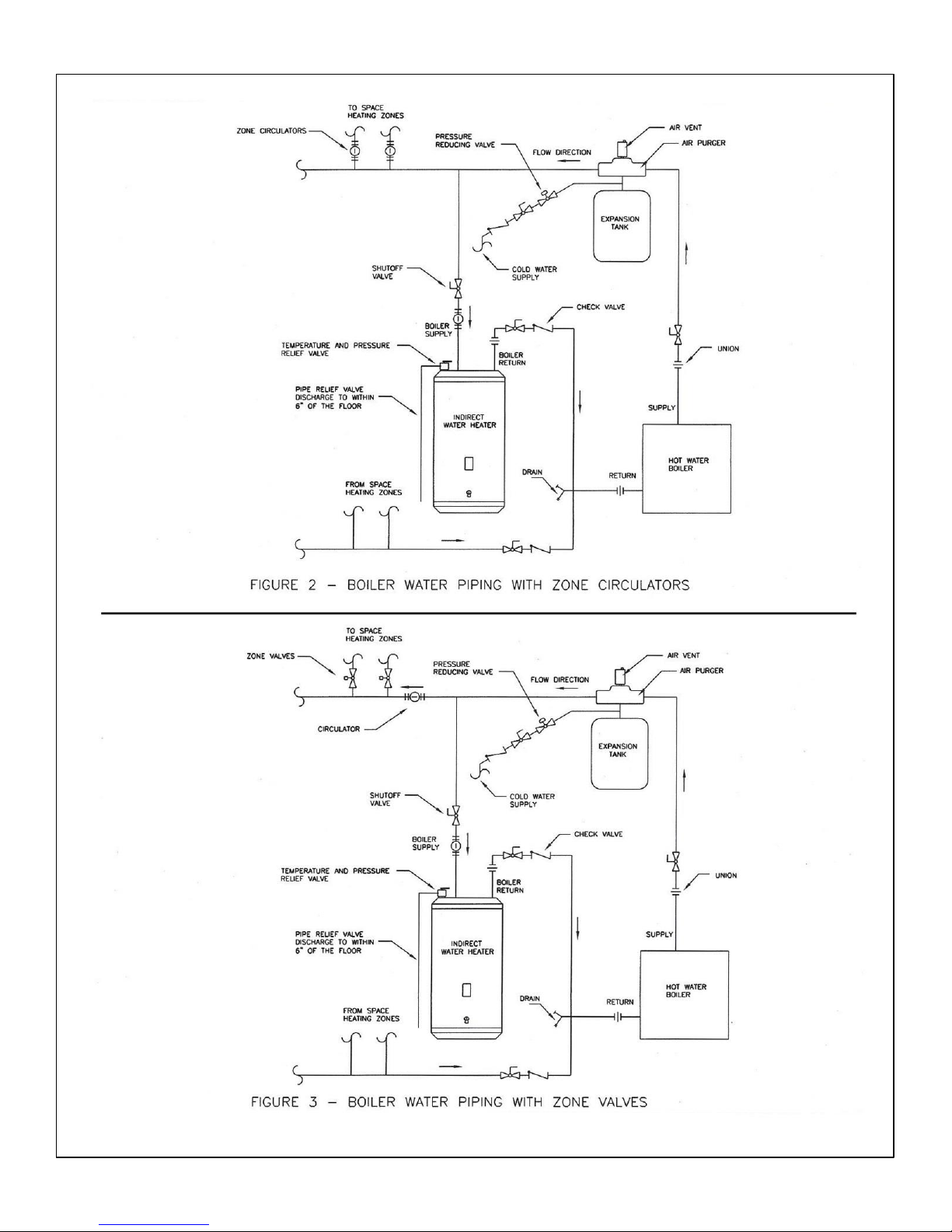
WATER BOILER PIPING (Refer to Figures 2, 3 on Pg. 10)
1. Determine where the boiler, the space heating, and the water heater connections should
be made based on the type of piping system that is either in place, or is to be installed for
a new hydronic system installation. See Figure 2 (Boiler Water Piping with Zone
Circulators) and Figure 3 (Boiler Water Piping with Zone Valves).
2. It is recommended that 1” pipe and 1” zone valves be used on the water heater zone on
residential sites, and 1-1/4” and 1-1/2” pipe be used on high output units on commercial
sites.
ZONE CIRCULATOR SYSTEM
For space heating systems that use Zone Circulators, refer to Figure 2. The water heater
connection labeled “BOILER SUPPLY” should be piped to the boiler supply piping after the air
purger and before the space heating takeoffs. Mount the water heater circulator as close to the
water heater as possible, and make sure the flow arrow points toward the water heater. The use
of shut-off valves is recommended for future service convenience.
The water heater connection labeled “BOILER RETURN” should be piped to the boiler return
piping as close to the boiler as possible and after any flow control or check valves in the space
heating return piping. The use of a union and a shut-off valve is recommended. The use of a check
valve is required to prevent back flow through the water heater during operation of the space
heating system.
ZONE VALVE SYSTEM
For a space heating system that uses Zone Valves, refer to Figure 3. The water heater connection
labeled “BOILER SUPPLY” should be piped to the boiler supply piping after the air purger and
before the space heating circulator. Mount the water heater circulator as close to the water
heater as possible, and make sure the flow arrow points toward the water heater. The use of a
shut-off valve is recommended for future service convenience.
The water heater connection labeled “BOILER RETURN” should be piped to the boiler return
piping as close to the boiler as possible and after any flow control or check valves in the space
heating return piping. The use of a union and a shut-off valve is recommended. The use of a check
valve is required to prevent back flow through the water heater during operation of the space
heating system.
Heat-Flo, Inc.| Indirect-Fired Water Heaters Page| 8
Page 14
Heat-Flo, Inc.| Indirect-Fired Water Heaters Page| 9
Page 15
Heat-Flo, Inc.| Indirect-Fired Water Heaters Page| 10
Page 16

ELECTRICAL
1. Install electric wiring and grounding in accordance with the National Electrical code (latest
edition) and/or local regulations in the US, and in accordance with the Canadian Electrical
Code (latest edition), and/or local regulations in Canada.
2. All water heaters are supplied with a thermostat.
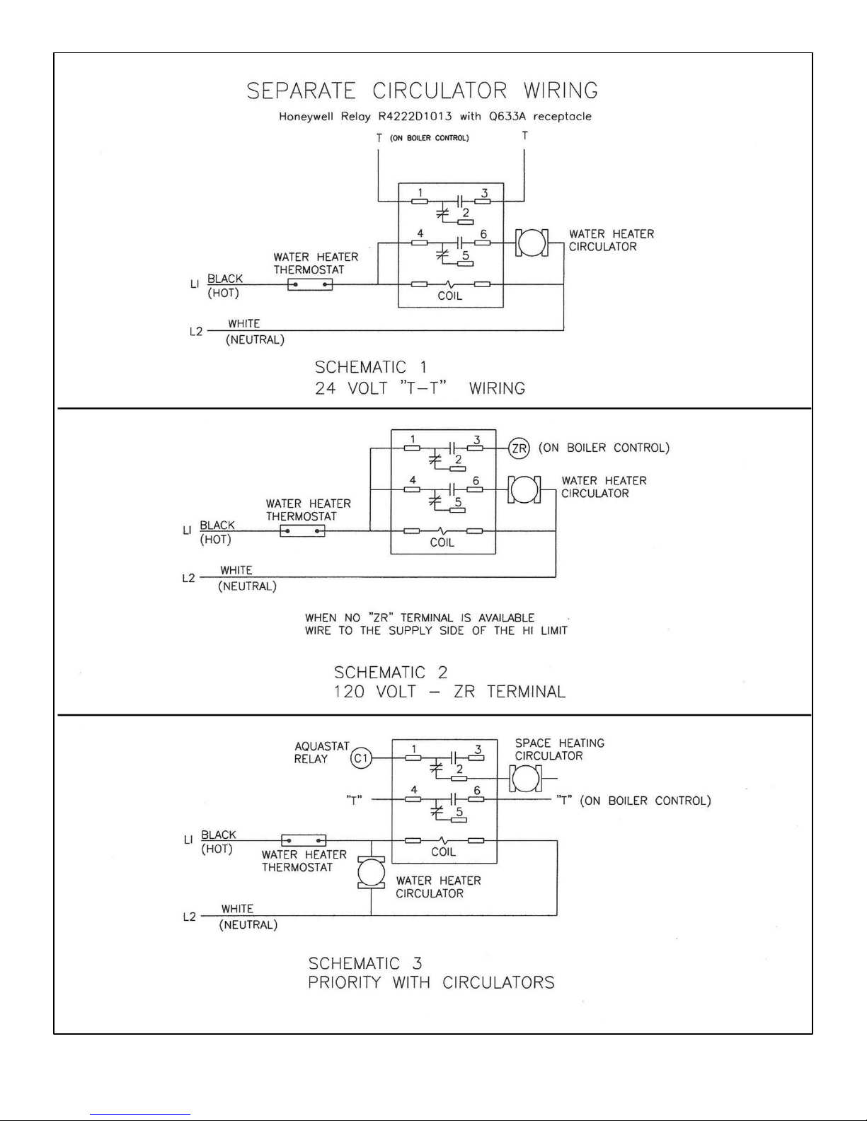
Refer to schematics 1, 2 and 3 for separate circulator wiring.
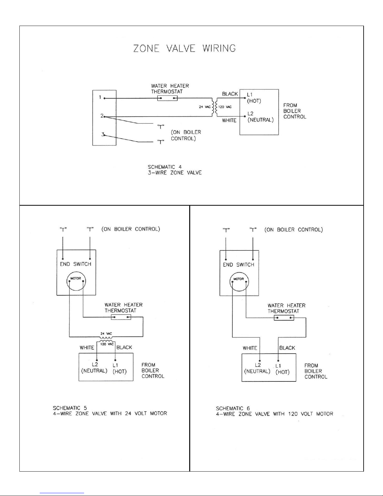
Refer to schematics 4, 5 and 6 for zone valve wiring.
Other options include using one of the many good zone controls that are on the market.
---Reference should be made to the Installation Manual for the boiler as well.---
OPERATION
STARTUP
After the water heater has been plumbed and wired and the boiler water piping is purged of air,
the water heater is ready to be started.
1. Follow the boiler installation instructions to place the boiler in operation.
2. The tank thermostat is factory pre-set to 125 degrees F and will call for heat if the water in
the tank is lower than that (125 deg. F).
3. On a call for heat, the tank thermostat contacts close to start the water heater zone circulator
and the boiler.
4. After the tank has reached the temperature setting, the tank thermostat opens and de-
energizes the circulator and the boiler. If there is a call for space heating, the boiler will
continue to run until the room thermostats are satisfied.
WARNING – SCALDING!
This water heater can deliver scalding temperature water at any faucet in the system. Be
careful when using hot water to avoid scalding injury. By setting the thermostat on this
water heater to obtain an increased water temperature, you create the potential for scald
injury. To protect against injury, you should install an ASSE approved mixing valve (a
device to limit the temperature of water to protect against scald injury via mixing hot and
cold water supply) in the water system. This valve will reduce point of discharge
temperature in branch supply lines. Such valves are available from a local plumbing
supplier. Please consult with a plumbing professional.
SCALD RELATIONSHIPS
The tank thermostat controls the maximum water temperature in the water heater. If it is set
too high, the resulting hot water can cause painful scalding with possible serious and permanent
injury. The temperature at which this occurs varies with a person’s age, and the length of time in
contact with the hot water. The slower response time of infants, older, or handicapped people
increases the hazard for them.
Heat-Flo, Inc.| Indirect-Fired Water Heaters Page| 11
Page 17
Heat-Flo, Inc.| Indirect-Fired Water Heaters Page| 12
Page 18
Heat-Flo, Inc.| Indirect-Fired Water Heaters Page| 13
Page 19
WATER TEMPERATURE ADJUSTMENT
It is recommended that the thermostat be set for the lowest possible temperature that satisfies
your needs. This will also provide you with the lowest energy consumption and cost.
Check the water temperature at a hot water faucet soon after the tank thermostat has satisfied,
and the circulator and the boiler have turned off. Adjust as needed.
Lowering the thermostat setting will not have an immediate effect on the water temperature
because the stored water will have to be used and the thermostat must go through the cycle of
heating cold water and satisfying at the new, lower temperature. Additional temperature checks
should follow the completion of a heating cycle. Further adjustments may be required after you
have used the water heater.
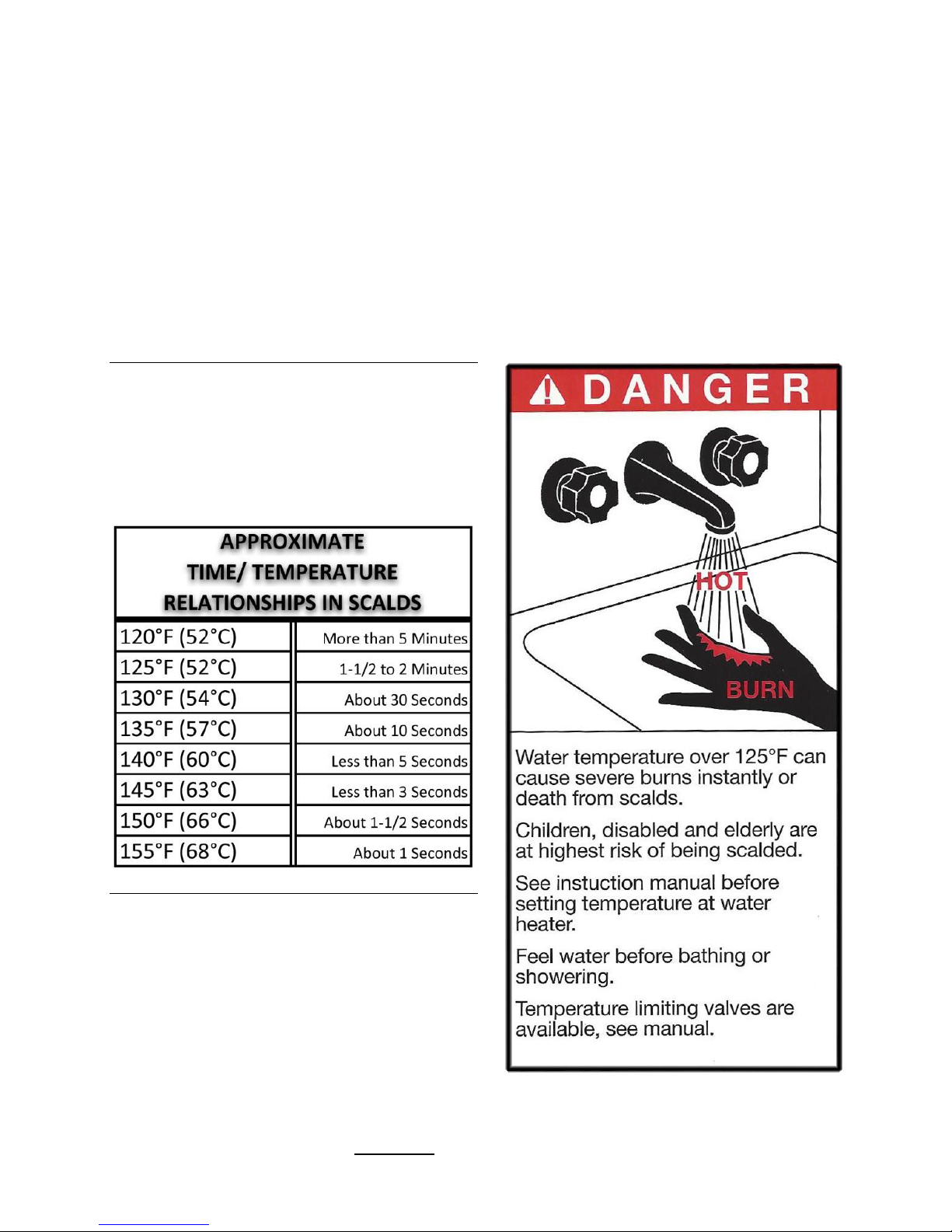
The table below details the approximate
relationship of water temperature and time
with regard to scald injury and may be used as
a guide in determining the safest water
temperature for your applications.
The scald label shown to the right can be found
on all Heat-Flo Indirect Water Heaters and
Storage tanks. Take note and use caution when
adjusting the temperature settings with your
water system. Be sure to always feel the water
before bathing or showering, especially when
drawing a bath for an infant or elder.
– Important WARNING information on the following page. –
Heat-Flo, Inc.| Indirect-Fired Water Heaters Page| 14
Page 20

WARNING
It is the responsibility of the installing contractor to see that all controls are correctly
installed and are operating properly when the installation is complete.
DO NOT operate the water heater with jumpered or absent controls or safety devices.
DO NOT tamper with or alter the water heater and/ or controls.
DO NOT operate the water heater if any external part has been under water. Immediately
call a qualified service technician to inspect the appliance and to replace any part of the
control system that is or had been under water.
DO NOT install this water heater on carpeting. This water heater is suitable for installation
on combustible flooring.
DO NOT operate this water heater without first being certain it is filled with water.
MAINTENANCE
The water heater is intended to provide many years of reliable service. Components, such as
thermostats and relief valves, may be subject to failures that require service. Depending on the
quality of the water supply, sediment and/or scale may coat the heating coil in the tank and
reduce hot water recovery rate. Failure to use the correct procedures or parts can result in unsafe
operation.
The owner should arrange to have the following inspections and simple maintenance procedures
done at the suggested frequencies.
1. Boiler and Domestic Water Piping (Annual)
Check all piping for signs of leakage at the joints, unions and shut-off valves. Repair as
required.
2. Temperature and Pressure Relief Valve (Annual)
The temperature and pressure relief valve should be checked to ensure that it is in
operating condition. To check the relief valve, lift the lever at the end of the valve several
times. The valve should seat properly and operate freely. If water does not flow, remove
and inspect for obstructions or corrosion. Replace with a new valve of the recommended
capacity as necessary. Do not attempt to repair the valve, as this could result in improper
operation and a tank explosion. In areas with poor water conditions, it may be necessary to
inspect the temperature and pressure relief valve more often than once a year.
CAUTION
Before manually operating the valve, make sure that a drain line has been attached to the valve
to direct the discharge to an open drain. Failure to take this precaution could mean contact with
extremely hot water discharging from the valve during this checking operation.
If the temperature and pressure relief valve on the heater discharges periodically or continuously,
it may be due to thermal expansion of water in a closed water supply system, or it may be due to
a faulty relief valve. Thermal expansion is the normal response of water when it is heated. In a
closed system, thermal expansion will cause the system pressure to build until the relief valve
actuation pressure is equaled. Then the relief valve will open, allowing some water to escape,
slightly lowering the pressure. Contact your water supplier or local plumbing inspector on how to
control this situation.
Heat-Flo, Inc.| Indirect-Fired Water Heaters Page| 15
Page 21

ABOVE ALL, DO NOT PLUG THE TEMPERATURE AND PRESSURE RELIEF VALVE. THIS IS NOT A
SOLUTION AND CAN CREATE A HAZARDOUS SITUATION.
3. Sediment (Annual except where harsh water quality may require more frequent service)
Depending on water conditions, a varying amount of sediment may collect in the tank.
Levels requiring service are indicated by a small temperature difference between the boiler
supply and return lines, and a reduced recovery rate. Repeated flushing usually clears such
material. As a preventive measure, water should be drawn from the drain valve until it runs
clear and the installation of a water filter should be considered.
4. Scale (Annual)
Hard water may cause scale buildup on the outside of the heating coil inside the tank. A
water softener will prevent this problem. Symptoms are identical to sediment buildup. If
repeated flushing does not resolve the problem, chemical cleaning may be required.
Proceed as follows:
CHEMICAL CLEANING OF THE HEATING COIL
1. To avoid water damage, shut off the cold water supply to the water heater.
2. Make a note of the temperature control setting on the water heater, and turn off the
power to the water heater.
3. Relieve the water pressure in the tank by opening a hot water faucet. This will reduce
the risk of scalding.
4. Remove the relief valve from the water heater.
5. Drain the water heater until the water is at a level equal to 3” above the thermostat
well. This level will cover the coil and the thermostat.
6. Using a funnel, pour one gallon of commercial ice maker cleaning solution into the tank
through the relief valve opening. Follow the instructions, cautions, and warnings
supplied with the cleaning solution.
7. Turn on the power to the water heater, and allow the boiler to heat the water until the
tank thermostat is satisfied. The boiler may cycle on its high limit several times during
this period. If the tank thermostat is not satisfied after 45 minutes of boiler operation,
turn the thermostat to its lowest setting.
8. Allow the heated solution to set in the tank 30 minutes.
9. Drain the tank completely using fittings and hoses, as required, to reach a drain.
10. Fill the water heater tank with fresh, cold, water and drain it completely. Repeat filling
and draining at least three (3) times to flush all of the cleaning solution from the tank.
11. Reinstall the relief valve and the drain piping.
12. Open the cold water supply and fill the tank with water. Purge the air from the tank and
the piping by opening the cold and hot water faucets in the house.
5. Inspect Anode (annual)
The purpose of the magnesium anode is to reduce the damaging effects of aggressive water
on the water heater. Aggressive water will cause the anode(s) to erode. The anode(s) must
be inspected at least annually to determine whether a new anode should be installed. Use
anode replacement parts supplied by Heat-Flo only. Heat-Flo anodes are 1-1/4 NPT and are
made with magnesium, brass, and stainless steel. There is no steel in a Heat-Flo anode.
Severe or rapid deterioration of the anode indicates very aggressive water. If this occurs,
have the water tested to verify whether it is within the limits outlined on page 6. Failure to
Heat-Flo, Inc.| Indirect-Fired Water Heaters Page| 16
Page 22

inspect the anode regularly and replace if necessary could result in damage to the water
heater. If this unit is installed and maintained according to the instructions and conditions
in this manual, this product will last for a long time.
1. Close domestic water isolation valves.
2. Drain the water heater completely and allow it to cool off.
3. Remove the anode cover on the front of the unit. See figures on pages 2 and 3. The
temperature control can be turned to the side to allow easier access.
4. After the water heater has drained and cooled, remove the anode using a 1 ¾” 6-point
socket and a breaker bar.
5. Inspect the anode and replace if needed. The anode should be replaced when more
than 6” of core wire is exposed. The anode should be replaced with a Heat-Flo supplied
anode only. See above. The brass hex on the anode is 1 ¼ NPT and installs into a 1 ¼
stainless half coupling on the shell of the tank. This part will need to be properly Teflon
taped and coated with a quality Teflon based pipe sealant.
6. Replace the inspection cover.
7. Refill the water heater, and restore to operation.
8. Verify operation of boiler and water heater.
Heat-Flo, Inc.| Indirect-Fired Water Heaters Page| 17
Page 23

TROUBLESHOOTING
PROBLEM
CAUSE
SOLUTION
No hot water at faucets.
Boiler does not operate
Circulator does not operate
Improper thermostat setting
Zone valve does not open
Electrical problem
Sediment and/or scale buildup
Clogged filter
Press reset button.
Check main cut-off switch.
Check fuses or breakers.
Check power supply.
Check shaft coupling.
Turn thermostat to a higher setting.
Check power supply and valve.
Check fuses and replace.
Check circuit breaker and reset.
Check power supply.
If boiler, circulator, and thermostat are
operating properly, and the boiler is
cycling on the high limit several times
before the tank thermostat is satisfied,
the coil may have a coating of sediment
and/or scale. See chemical cleaning
instructions (Pg. 16).
Clean or replace filter.
Insufficient/ runs out of hot water at the
faucet.
Thermostat setting too low.
Undersized boiler with no priority
to domestic water heating.
Peak draw of hot water is greater
than the tank storage.
Sediment and/or scale buildup
Faulty water heater thermostat
Turn the thermostat to a higher setting.
Rewire for priority.
Determine peak usage and compare to
tank volume.
Clean coil.
Replace thermostat.
Water at faucet too hot.
Thermostat set to high
Improper system plumbing
Improper wiring
Lower thermostat setting.
Compare plumbing to installation guide.
Inspect check valves.
Compare wiring to installation guide.
Boiler cycles more than 5 times per day
in summer.
Excessive demand
Faulty thermostat
Boiler high limit set to low
Sediment and or scale buildup
Reduce demand or consider larger
boiler and/or water heater.
Replace thermostat.
Increase boiler hi-limit setting.
Clean coil.
Heat-Flo, Inc.| Indirect-Fired Water Heaters Page| 18
Page 24
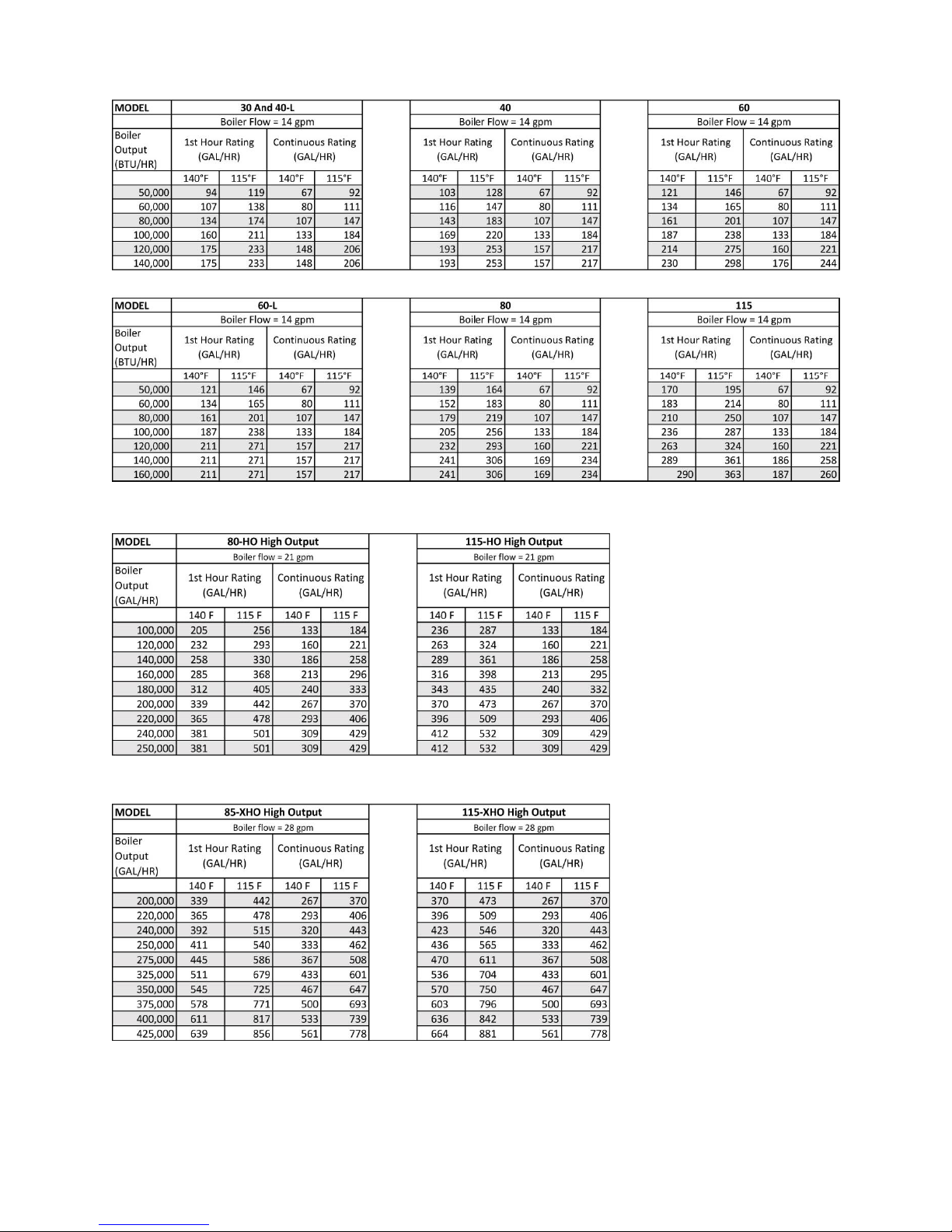
180°F Boiler Supply
IBR Rating Condition
HIGH OUTPUT UNITS: 80-HO, 115-HO
EXTRA HIGH OUTPUT UNITS: 85-XHO, 115-XHO
Heat-Flo, Inc.| Indirect-Fired Water Heaters Page| 19
Page 25
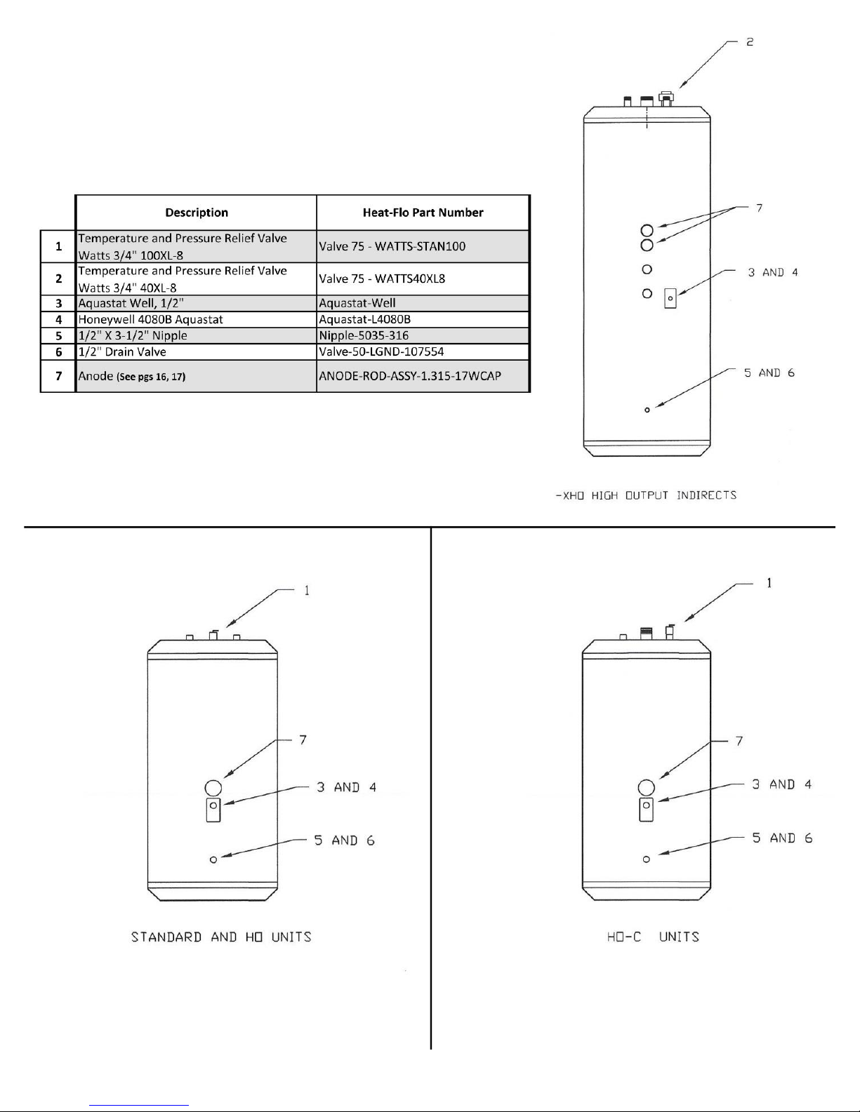
Replacement Parts List
Heat-Flo, Inc.| Indirect-Fired Water Heaters Page| 20
Page 26

Heat-Flo, Inc.
LIMITED WARRANTY
FOR INDIRECT WATER HEATER
These Heat-Flo, Inc. warranties protect your indirect-fired water heater. These warranties are applicable to the original purchasers only.
WARRANTY COVERAGE FOR RESIDENTIAL USAGE
The warranties listed in this section shall apply to Heat-Flo, Inc., indirect-fired water heaters used in a residential setting by the original
consumer purchases only. A “residential setting” as used herein shall mean usage in a single-family dwelling in which the original
consumer purchaser of the indirect-fired water heater resides on a permanent basis. “Residential setting” shall also mean usage in a
multiple family dwelling provided that a Heat-Flo, Inc. indirect-fired water heater services only one (1) dwelling in a multiple family
dwelling. The term “residential setting” shall not include any usage of the indirect-fired water heater above 150 degrees Fahrenheit.
Heat-Flo, Inc. warrants that it will repair or replace, at its option, without charge, any defective or malfunctioning component of the
water heater during the first year after the original date of installation in the dwelling. It is expressly agreed between Heat-Flo, Inc. and
the original consumer purchaser that repair or replacements are the exclusive and sole remedy of the original consumer purchaser.
During the remaining lifetime of the water heater, Heat-Flo, Inc. will repair or replace, at its option, without charge, any water heater
having a defect or malfunction that results in a water leak from outer the jacket, inner tank, or heat exchanger as a result of normal use
and service. It is expressly agreed between Heat-Flo, Inc. and the original consumer purchaser that the repair or replacement is the
exclusive and sole remedy of the original consumer purchaser.
Should a defect or malfunction result in a leakage of water within the above-stated warranty periods due to defective material or
workmanship, malfunction, or failure to comply with the above warranty, such defect or malfunction having been verified by an
authorized Heat-Flo, Inc. representative, then Heat-Flo, Inc. will replace the defective or malfunctioning water heater with a replacement
water heater of the nearest compatible model available at the time of replacement.
If Heat-Flo, Inc. is unable to repair or replace a water heater so as to conform to this warranty, after a reasonable number of attem pts,
then Heat-Flo, Inc. will provide at its option, either a replacement product, or a full refund of the purchase price. These remedies are the
consumer purchaser’s exclusive remedies for breach of the warranty.
WARRANTY COVERAGE FOR COMMERCIAL USAGE
The warranties listed in this section shall apply to Heat-Flo, Inc. water heaters used in a commercial setting by the original consumer
purchasers only. A “commercial setting” as used herein shall mean any usage not falling within the above definition of a “res idential
setting”. A Heat-Flo, Inc. water heater shall be deemed used in a “commercial setting” if at any time it is operated at a temperature
above 150 degrees Fahrenheit.
Heat-Flo, Inc. warrants that it will repair or replace, at its option, without charge, any defect or malfunctioning of the water heater during
the first year after the original date of delivery to the original consumer purchaser. It is expressly agreed between Heat-Flo, Inc. and the
original consumer purchaser that the repair or replacement is the exclusive and sole remedy of the original consumer purchaser.
During the second through fifth years after the original date of delivery to the original consumer purchaser, Heat-Flo, Inc. will repair or
replace, at its option, without charge, any water-heater having a defect or malfunction that results in a water leak from the outer jacket,
inner tank, and heat exchanger as a result of normal use and service. It is expressly agreed between Heat-Flo, Inc. and the original
consumer purchaser that the repair or replacement is the exclusive and sole remedy of the original consumer purchaser.
Should a defect or malfunction result in a leakage of water within the above-stated warranty periods due to defective material or
workmanship, malfunction, or failure to comply with the above warranty, such defect or malfunction having been verified by an
authorized Heat-Flo, Inc. representative, then Heat-Flo, Inc. will replace the defective or malfunction water heater with a replacement
indirect water heater of the nearest comparable model available at the time of replacement.
If Heat-Flo, Inc. is unable to repair or replace the water heater so as to conform with this warranty after a reasonable number of attempts,
then Heat-Flo, Inc. will provide, at its option, either a replacement product, or a full refund of the purchase price. These remedies are
the exclusive remedies of the original consumer purchaser See reverse side for exclusions, limitations, remedies and service request
information.
Bulletin WAR-071514 Page 1 of 2
Heat-Flo, Inc.| Indirect-Fired Water Heaters Page| 21
Page 27

WHAT IS NOT COVERED BY EITHER OF THESE WARRANTIES
Heat-Flo, Inc. does not warrant:
1. Defects or malfunctions resulting from improper installation or failure to maintain and operate an indirect-fired water heater in
accordance with the printed instructions which accompany the water heater.
2. Defects or malfunctions resulting from consumer damage, such as: (A) improper maintenance or (B) misuse, abuse, accident, or
alteration.
3. Defects or malfunctions on indirect-fired water heaters where the original serial number cannot be readily determined.
4. Service calls not involving malfunction or defects in materials or workmanship, and the original consumer purchaser shall pay for such
calls.
5. Water heaters installed outside of the United States and Canada.
6. Water heaters repaired or altered without prior written approval of Heat-Flo, Inc. so as to affect adversely their reliability.
7. Components of an indirect-fired water heater which are not defective, but must be replaced during the warranty period as a result of
reasonable wear and tear.
8. Components of an indirect-fired water heater which are subject to warranties, if any, given by their manufacturers. Heat-Flo, Inc. does
not adopt these warranties.
9. Malfunctions resulting from, or repairs necessitated by, a failure to maintain an indirect-fired water heater free of water sediments or
scale deposits.
10. This warranty does not extend to labor costs, shipping charges, delivery expenses, or administrative fees incurred by the original
household consumer purchaser in repairing or replacing an indirect-fired water heater.
Heat-Flo, Inc. will not accept claims for labor costs incurred by the original consumer purchaser in removing or reinstalling
an indirect-fired water heater.
11. Malfunctions resulting from, or repairs necessitated by, uses of the indirect-fired water heater for purposes other than that for which
it was designed, or resulting from flood, fire, wind, or lightning.
OWNER’S RESPONSIBILITIES
The owner or installer must:
1. Have the storage tank installed with a vacuum relief valve and a temperature and pressure relief valve in accordance with local, state,
and federal codes and ordinances bearing the listing marks of the American Society of Mechanical Engineers (A.S.M.E).
2. Operate the storage assembly at a pressure below that shown on the rating plate on the pressure relief valve.
3. Keep the tank free of scale deposits.
4. Make provisions so if the tank or any component part or connection should leak, the resulting flow of water will not cause
damage to the area in which it is installed.
The warranty hereunder does not apply to defects resulting from:
1. Freezing, excessive pressure, or leaks at water connections.
2. Failure of a component, control or component part other than a component part manufactured solely by HFI.
3. Any cause similar to the above, not resulting solely due to defective material and/or workmanship.
4. Water Quality: The warranties extended by HFI are conditioned upon potable water with a Ph not to exceed 8.0 and not below 6.0,
and/ or chloride concentrations not to exceed 100 parts per million (ppm). HFI specifically disclaims liability of any kind resulting from
or relating to potable water that does not match these characteristics.
LIMITATION OF WARRANTIES AND REMEDIES
THE FOREGOING WARRANTIES ARE EXCLUSIVE AND ARE GIVEN AND ACCEPTED IN LIEU OF ANY AND ALL OTHER WARRANTIES,
EXPRESS OR IMPLIED, INCLUDING WITHOUT LIMITATION THE IMPLIED WARRANTIES OF MERCHANTABILITY AND FITNESS FOR
PARTICULAR PURPOSE, AND ANY OBLIGATION, LIABILITY, RIGHT, CLAIM, OR REMEDY IN CONTRACT OR TORT, WHETHER OR NOT
ARISING FROM HEAT-FLO, INC.’S NEGLIGENCE, ACTUAL OR IMPUTED.
THE REMEDIES OF THE ORIGINAL CONSUMER PURCHASES SHALL BE LIMITED TO THOSE PROVIDED HEREIN TO THE EXCLUSION
OF ANY OTHER REMEDIES INCLUDING WITHOUT LIMITATION, INCIDENTAL OR CONSEQUENTIAL DAMAGES INCLUDING, BUT NOT
LIMITED TO, PROPERTY DAMAGE, LOST PROFIT, OR DAMAGES ALLEGED TO HAVE BEEN CAUSED BY ANY FAILURE OF HEAT-FLO,
INC. TO MEET ANY OBLIGATION UNDER THIS AGREEMENT INCLUDING THE OBLIGATION TO REPAIR AND REPLACE SET FORTH
ABOVE.
NO AGREEMENT VARYING OR EXTENDING THE FOREGOING WARRANTIES, REMEDIES, OR THIS LIMITATION WILL BE BINDING
UPON HEAT-FLO, INC. UNLESS IN WRITING AND SIGNED BY A DULY AUTHORIZED OFFICER OF HEAT-FLO, INC.
THE WARRANTY STATED HEREIN IS NOT TRANSFERABLE AND SHALL BE FOR THE BENEFIT OF THE ORIGINAL CONSUMER
PURCHASER OF A WATER HEATER ONLY.
These warranties give you specific legal rights, and you may also have other rights which vary from state to state. Some states do not allow the
exclusion or limitation of incidental or consequential damages so this limitation or exclusion may not apply to you.
These are the only written warranties applicable to water heaters manufactured and sold by Heat-Flo, Inc. Heat-Flo, Inc. neither assumes nor
authorizes anyone to assume for it any other obligation or liability in connection with said water heaters.
SERVICE REQUESTS
FOR SERVICE UNDER THESE WARRANTIES CONTACT HEAT-FLO, INC., AT THIS ADDRESS:
At the time a claim is filed the original consumer purchaser must present a copy of the original sales receipt, and a deed, utility bill, or equivalent
document evidencing both ownership of the water heater and installation in the dwelling or commercial property owned by the original consumer
purchaser. With regard to claims made by original consumer purchasers of water heaters used in commercial settings as that term is defined
herein, in no event shall notification of a service request be received later than five years from the date of purchase.
The obligations under this warranty apply only to domestic hot water tank installations where the warranty registration card has been
completed by the owner of the site of the original installation and received by Heat-Flo in accordance with the terms and conditions herein set
out and Heat-Flo has been notified of the alleged defect or deficiency within forty eight (48) hours from the occurrence or discovery of the
alleged defect or deficiency. Heat-Flo, Inc. reserves the right to change specifications or discontinue models without notice.
Bulletin WAR-071514 Page 2 of 2
Heat-Flo, Inc., P.O. Box 612, Uxbridge, MA 01569
Heat-Flo, Inc.| Indirect-Fired Water Heaters Page| 22
Page 28

Heat-Flo, Inc.
15 Megan Ct.
P.O. Box 612
Uxbridge, MA 01569
| Tel: (508)-278-2400 | | Fax: (508)-278-2466 |
www.heat-flo.com
 Loading...