

Page 1
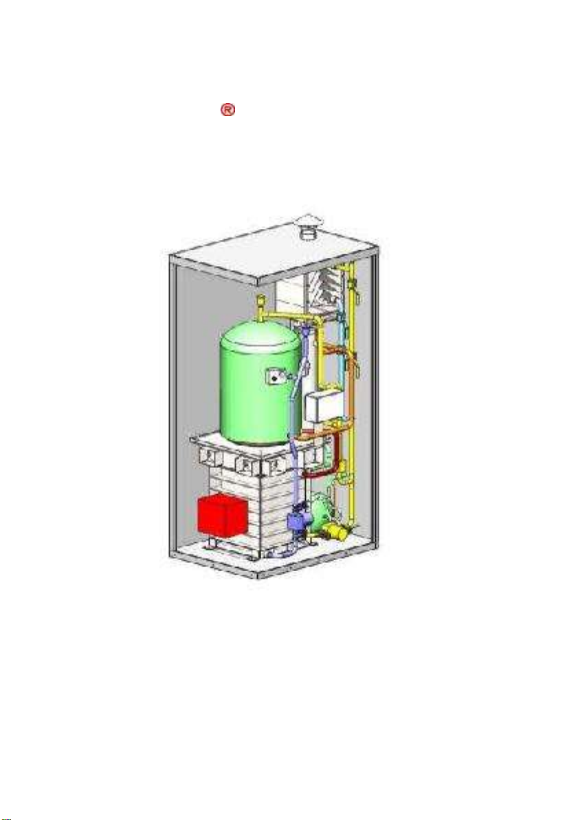
Installation, Commissioning and Instruction manual
HEATESE
Unique heating system
“Lavish on heat, miserly on fuel” TM
80
Always On, Always Warm
HEATESE issue (1) 08/2016
Page 2
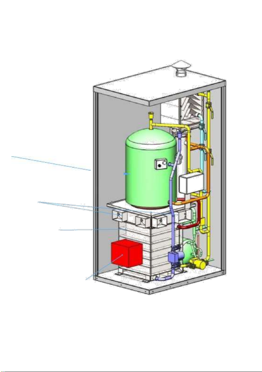
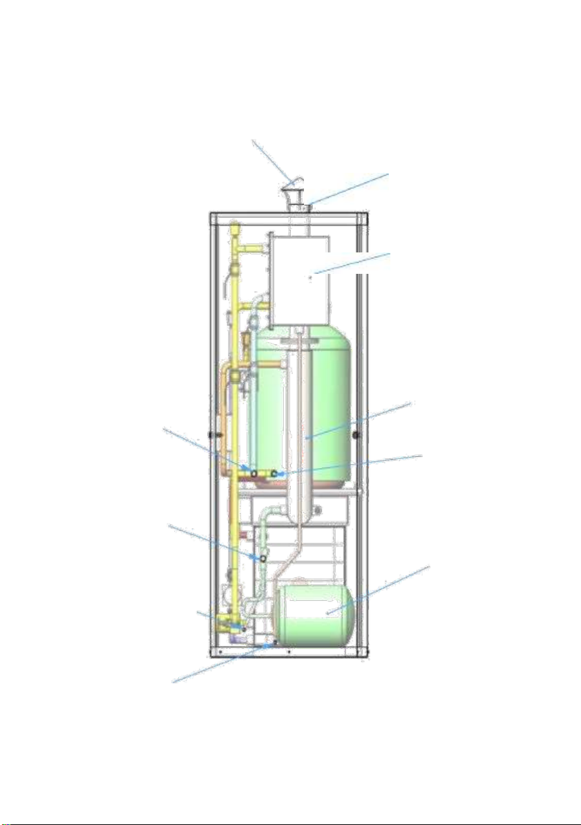
Insulated and Baffled 80L Copper
Cylinder with Heat-Sync on base
3 off Small Cleaning Ports
1 off Large Cleaning Port
to facilitate
Flue Cleaning
Oil Fired Burner with Fuel
Safety Valve located
externally at rear of
enclosure (sensor located
internally above burner)
Page 1
Page 3
Page 2
Page 4
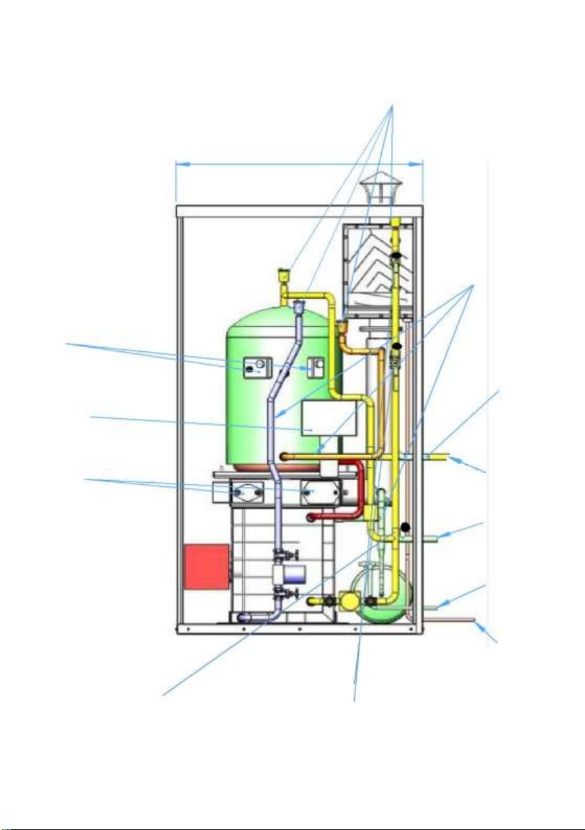
Thermostats
Electrical Panel
Trip switch,
Timer, Relay
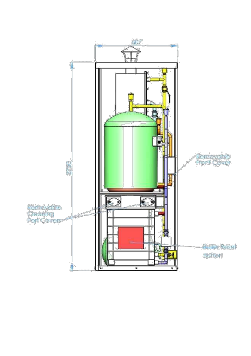
Removable
Cleaning Port
Covers
Automatic filling valve Lever valves
Automatic Air Vents at
high points in circuits
1107
Pressurised
Closed Loop
(Blue, Orange &
Green)
Return From
Dwelling
Hot Feed to
Mains Cold
Water Feed
(1.5 Bar G Max)
Pressure Relief
set at 3.0 bar
G max.
Condensate
Out
Page 3
Page 5
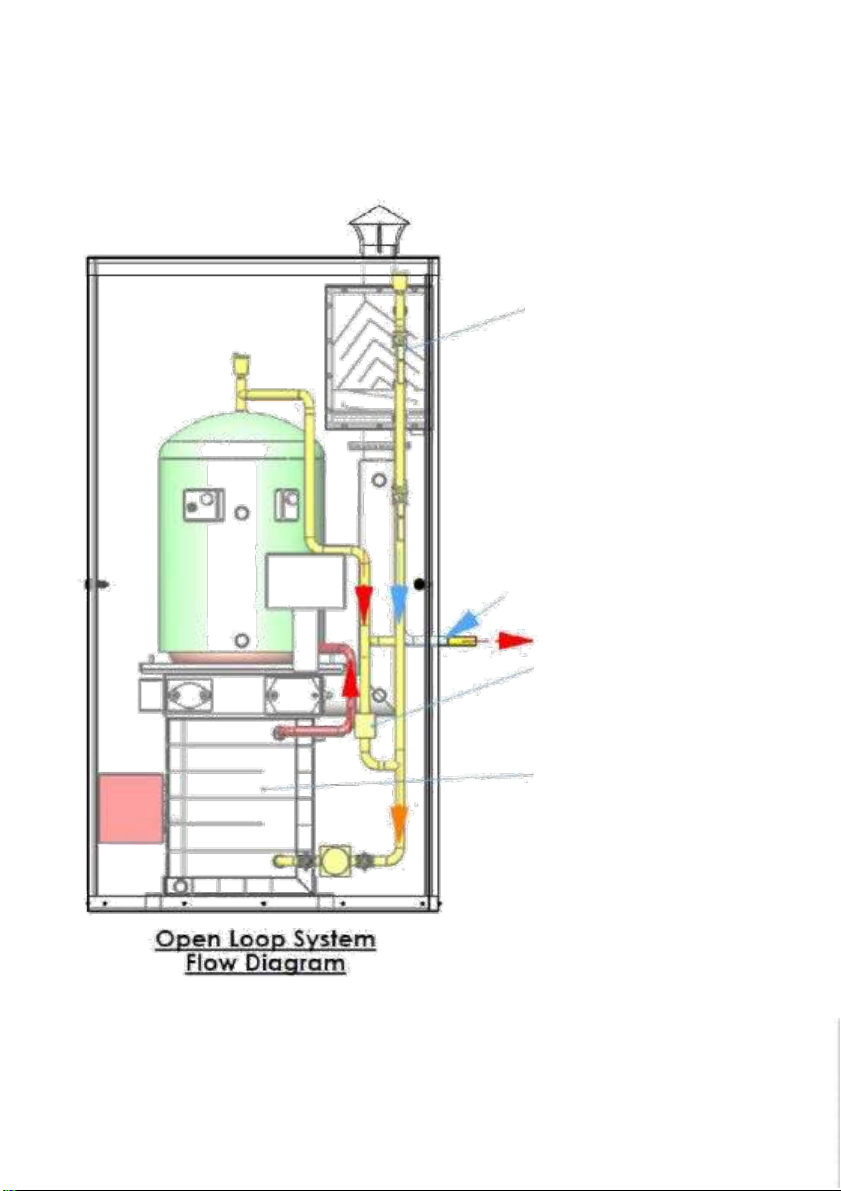
Weather Cowl
Return Feed
from Dwelling
Mains Feed
(1.5barG Max)
Pressure Safety Valve
opens to relieve
pressure at 3.0barG
Condensate Out
Flue Gas Exhaust
Flue Gas Condenser
Heat Exchanger
Hot Feed
to Dwelling
18 L Pressure
Vessel
Page 4
Page 6
Condenser preheats return
Dwelling water before C
Shaped Baffled Boiler
Motorized Valve is open until
the Cylinder Thermostat (B)
reaches 50°C, the valve then
closes and feeds to dwelling,
which thermostat (A) would be
set at 60
0
C.
C Shaped Baffled Boiler
transfers Heat to preheat
cylinder contents in addition
to Cylinder Coil
Page 5
Page 7
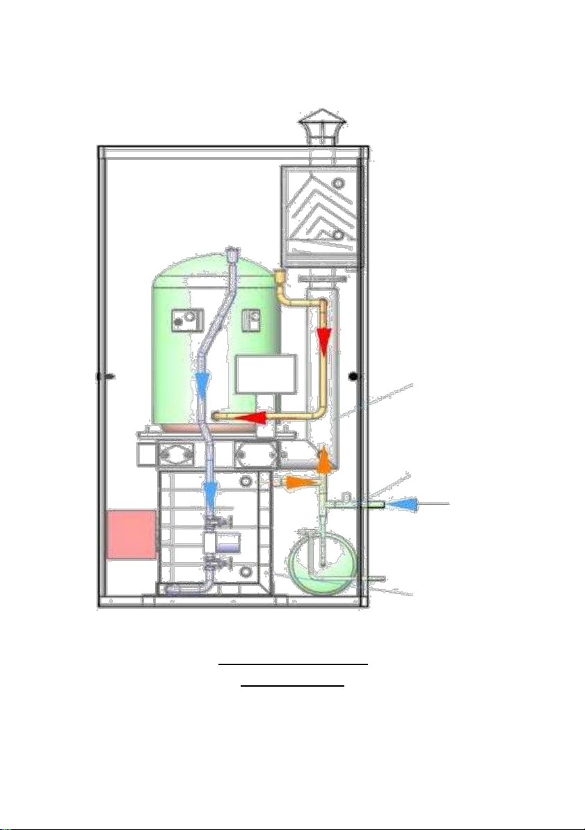
Closed Loop System
Flow Diagram
Page 6
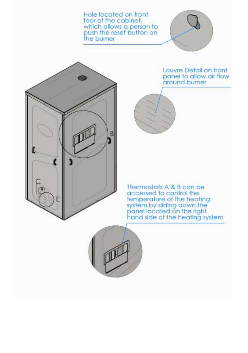
Jacketed Flue Pipe
transfers Heat into Loop
which is circulated
through Cylinder Coil
Mains Cold Water Feed
for Initial Fill and Top-
Ups
L-Shaped Baffled Boiler
Wall transfers Heat into
Loop which is circulated
through Cylinder Coil
Page 8
Page 7
Page 9
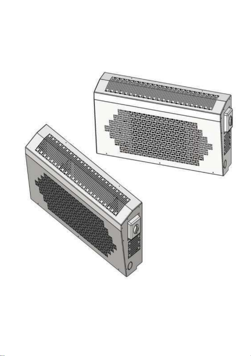
CONVECTOR RADIATORS
Page 8
Page 10

CONTENT
LAYOUT AND COMPONENTS………………….1-7
INTRODUCTION /WARRANTY ........................... 11
SAFETY INSTRUCTIONS .................................... 13
MAINTENANCE TIPS ........................................... 14
REGULAR SERVICING ........................................ 15
GENERAL INFORMATION………………………..16
PRE-INSTALLATION............................................. 18
INSTALATION GUIDE........................................... 20
HEATESE USER GUIDE ...................................... 27
ELECTRICAL CONNECTIONS ........................... 29
WIRING DIAGRAM ................................................ 30
POSITIONING GUIDE........................................... 31
TECHNICAL DATA TABLE – HEATESE 80 ...... 33
CONVECTOR RADIATORS................................. 37
CONVECTOR RADIATOR WARRANTY ........... 39
CONVECTOR RADIATOR DATA………………...40
HEATESE 80 HEATING SYSTEM FAULT
FINDING GUIDE .................................................... 52
HEATESE COMMISIONING CHECKLIST......... 54
SERVICE RECORD............................................... 57
HEATESE CONTACT NUMBERS ...................... 60
Page 9
Page 11
This symbol indicates Caution and it is placed next to all safety warnings.
Strictly follow these instructions to avoid danger and damage to persons,
animals and things.
This symbol calls attention to a note or important notice.
Declaration of conformity
Manufacturer: Low Flame Boilers Ltd.
Address: Carnisle, Ballivor, Co. Meath, Ireland
Declares that the unit complies with the following EU directives:
Efficiency Directive 09/2015
Low Voltage Directive 07/2015
Electromagnetic Compatibility Directive
07/2015 Sound testing Directive 09/2015
Director and Legal Representative
Patrick Kiely
Cormack Lohan
Page 10
Page 12

INTRODUCTION /WARRANTY
Thank you for choosing a HEATESE Heating System. We are sure that you will be
satisfied with the performance of your new heating system and with the ongoing
service that you will receive.
Reliability
Every new HEATESE Heating System leaving our factory and installed by a HEATESE
approved engineer carries a five years guarantee on parts (certain consumable parts
are excluded – for full details see below). This also includes all labour charges for the
first 12 months.
Distribution and Service Network
HEATESE have set up a distributor and service network with fully trained service
engineers available to support your HEATESE Heating System within the period of the
guarantee and after. The approved engineer installing your HEATESE Heating System
is responsible for providing this warranty.
Ensure that the service engineer completes the Service Record, at the
rear of the Installation, Commissioning and Servicing Instruction manual,
after each service.
Ensure that the service engineer completes the Commissioning part of
the manual.
Have any work carried out only by a competent HEATESE registered engineer.
Always use original spare parts, to help maintain the efficiency, safety and
reliability of the appliance.
No charge will be made for replacement parts providing:
An appliance fault is found.
There will be no charges during the first 12 months of the warranty.
The relevant part of the HEATESE Heating System is still covered by
guarantee.
Regular servicing has been carried out in accordance with the
manufacturer’s instructions by authorised HEATESE engineers, using
approved parts. Please note: The service booklet will need to be completed
accordingly.
Page 11
Page 13

A call out charge may be applicable if:
The authorised HEATESE service engineer who calls to your home finds no
fault with the HEATESE Heating System.
Other parts of your plumbing system are either faulty or do not comply
with the appropriate installation instructions.
The unit is more than 12 months old.
Please note: Invoices for callout repair work carried out during the guarantee period
by any third party cannot be accepted.
In the event of an appliance fault during the guarantee period, please contact your
service provider. They will arrange for an engineer to call out as soon as possible.
Warranty
What is under guarantee:
5 Year warranty on circulating
pumps 5 Year warranty on fire valve
5 Year warranty on main structure of the heating
system 5 Year warranty on all pipes and fittings
1 Year warranty on thermostats
1 Year warranty on the Reillo burner 1
Year warranty on motorised valve
1 Year warranty on all electrical components 1
Year warranty on all pipe insulation
1 Year warranty on 3 bar pressure release
valve 1 Year warranty on automatic filling valve
1 Year warranty on pressure vessel 1
Year warranty on air vents
1 Year warranty on oil filter
What is not under guarantee:
Labour charges not directly connected with the repair or replacement of a
faulty component.
Any consequential loss.
Accidental or cosmetic damage.
Routine preventative service and maintenance.
Page 12
Page 14

SAFETY INSTRUCTIONS
General information:
These operating instructions are intended for the user of the heating system.
Read any operating instructions (heating system, heating controls,
ect.) carefully before operation and keep them.
Observe the safety instructions and warnings.
Oil fumes or leaks from the appliance
If you smell oil fumes, observe the following rules:
Extinguish any naked flames
Isolate the electricity supply
Isolate the fuel supply to the heating
system Open windows and doors
Rectify the fault
Health and safety
The appliance contains no asbestos and no substances have been used in the
construction process that contravene the COSHH Regulations (Control of
Substances Hazardous to Health Regulations 1988). Where applicable, the CE mark
indicates compliance with relative EU Directives.
Combustible substances
The area, where the installation of the heating system, must be free of
combustible or chemically aggressive substances.
Do not use or store combustible or explosive materials (paper,
propellants, thinners, paints, ect.) within the vicinity of the appliance.
Do not use or store corrosive substances (solvents, adhesives,
chlorinated cleaning agents, ect.) within the vicinity of the appliance.
Appliance operation
This appliance can be used by children aged from 8 years and above and persons
with reduced physical, sensory or mental capabilities or lack of experience and
knowledge, if they have been given supervision or instruction concerning the use
of the appliance, in a safe way, and understand the hazards involved.
Children shall not play with the appliance.
Cleaning and user maintenance shall not be made by children without supervision.
Page 13
Page 15

Intended use
This appliance must only be used as a heat appliance in an open vented hot
water heating system for domestic purposes.
Any misuse or unauthorised modifications to the appliance, flue or
associated accessories and heating system will invalidate the guarantee.
Do not modify the appliance or flue system in any way.
Low Flame Boilers Ltd accepts no liability arising from any such actions. This
does not affect your statutory rights.
Handling Instructions and Guidelines
It is advised that more than one person is involved in the transfers of the
packaged appliance from the van to the point of installation.
It is advised that no attempt should be made to move the packaged
appliance without the use of a suitable truck.
At all times the correct method for handling heavy objects should be
strictly observed.
Lift only a manageable weight, or ask for help
When lifting, bend knees, and keep the back straight and feet apart. Do
not lift and twist at the same time.
Lift and carry items close to the body.
Wear protective clothing and gloves to protect from any sharp edges.
MAINTENANCE TIPS
Regularly check the oil level in the tank.
Do not obstruct the flue outlet or the air inlet.
Regularly check the system pressure gauge, to make sure that it is between ½
and 1½ bar pressure.
Check power to the heating system.
Check all control settings.
Use in hard water areas
In exceptionally hard water areas a device to prevent scale formation may be
fitted. Installation of scale inhibitor assembly should be in accordance with the
requirements of the local water company.
As isolation valve should be fitted to allow for servicing.
Page 14
Page 16

REGULAR SERVICING
Regular maintenance is an essential part of keeping your HEATESE Heating System
running safely and efficiently.
Since your HEATESE Heating System operates for long intervals it is important to
ensure regular servicing is undertaken by your Authorized HEATESE engineer. Only
genuine HEATESE spare parts should be used.
Please note: Routine servicing in accordance with the manufacturer’s instructions is
also a condition of the warranty agreement.
To ensure your HEATESE Heating System receives this essential maintenance, please
contact your Distributor or service provider who will be pleased to help.
Service Intervals:
Every 12 months.
Exclusions
The warranty does not cover products which have been altered by the customer or
by third parties. All materials and spare parts must be recommended by HEATESE.
The warranty does not cover misuse, abuse or impact damage.
The warranty strictly excludes commercial use. Appliances are covered for domestic
use only.
Flues, Ventilations and External Services
External oil lines, tanks and filters are not covered under this warranty. Nor does the
warranty cover incorrectly operated or a poorly maintained HEATESE Heating System.
Product fuel conversions are not covered.
This warranty policy does not affect the owners’ statutory rights
Page 15
Page 17

GENERAL INFORMATION
Your HEATESE Installation, Commissioning and Service Record Log Book
are located on the last pages of this manual. All service records must be
logged and kept up to date by end user.
HEATESE can only be installed and serviced by a HEATESE engineer.
According to the current regulation and the manufacturer’s instructions,
all incorrect installations or poor maintenance can cause damage or
physical injury. The manufacturer will decline any responsibility for
damage by errors in the installation and use, or by not following the
manufacturer’s instructions.
HEATESE declares that no harmful materials are used in the
manufacturing of this product.
This instruction book should be carefully read as it provides all information on
all aspects of the heating system. This manual must accompany the heating
system at all times and all other component manuals, especially in the event of
the heating system changing ownership.
Before cleaning or maintenance is carried out DISCONNECT AND ISOLATE
the heating system from the electrical supply.
If the system stops working or it is not operating as normal contact your
HEATESE engineer. Only HEATESE parts from the manufacture can be
used. Failure to comply with these guidelines could affect the safety and
operations of the unit.
Yearly maintenance has to be carried out by a qualified HEATESE engineer
to guarantee good operation of the unit.
This unit must only be used for the purpose for which it was designed for
i.e., for domestic use only. Any other use is considered to be improper and
therefore hazardous.
After removing the packaging, check the integrity of the contents. In case
of any doubt do not use the unit, and contact the supplier.
The images shown in this manual are a simplified representation of the
product. In this representation there may be slight, unimportant
differences with the supplied product.
Every effort is taken to ensure the accuracy of the information contained in
these instructions. The details are offered in good faith and the
manufacturer accepts no liability for matters arising as a result of errors
and / or omissions.
Due to manufacturer’s continuous product research and development, the
details contained in this manual may not truly reflect the actual product.
Page 16
Page 18

Packing materials must be kept out of reach from children as they are
potentially hazardous.
General notes
To get the best from your heating system, read these instructions carefully.
Central heating system
During the first few hours of operation of the central heating system, check that all
radiators are being heated at even rate. If the top of the radiator is at lower
temperature that the bottom then it should be vented by releasing air through the
venting screw at the top of the radiator. Ask your installer to show you how this is
done. Repeated venting will reduce the quantity of water in the system and this must
be replenished for safe and satisfactory operation of the heating system.
When excessive venting or water leaks are found in the system you must contact a
HEATESE service engineer to inspect the installation and rectify any fault.
Only use additives compactible with the heating system. Use of incompatible
additives can cause damage and will invalidate the guarantee.
Condensate drain
This is a condensing heating system and the terminal will, at times give out a plume
of water vapour. This is quite normal.
The heating system also produces quantities of condensate which is discharged
regularly via a pipe to drain.
This pipe must not be blocked or altered in any way.
Clearances
Your installer will have provided adequate space around the heating system for
safety and servicing access.
Do not restrict this space next to the heating system.
FROST PROTECTION
Class VII temperature control stat can be wired into the heating system.
Frost protection should be fitted to the system where the system is most
exposed and at risk of freezing.
Page 17
Page 19

PRE-INSTALLATION
Cleaning primary systems
Before cleaning the system
Follow the guidance of BS7593:
Treatment of water in domestic hot water central heating and also the
flushing guidelines below:
Fill the system with cold water and check for leaks.
Danger to life through electrical shock!
Before carrying out any work on electrical components,
isolate them from the power supply (230V AC) (fuse, circuit
breaker) and secure against unintentional re-connection.
Risk of damage to appliance or accessories!
All the following pre-installation sections must be read and
requirements met before starting the appliance or flue installations.
Risk of damage to system or appliance!
Debris from the system can damage the appliance and reduce
efficiency. Failure to comply with guidelines for the use of
water treatment with the appliance will invalidate the
guarantee and contravene the Building Regulations.
It is a requirement of the Building Services Compliance Guide
which is a second tier document to the Building Regulations to flush
and inhibit the primary water system in accordance with BS 7593.
HEATESE states you must fit a filter that will help
remove both magnetite and non-magnetite debris.
Ensure that the system and pipe work is in good working order.
Where possible keep the existing appliance/ circulating pump in
place when flushing the system.
Turn off the water to the system header tank.
Open all drain cocks and drain the system.
Page 18
Page 20

Close drain cocks and add suitable flushing agent at the correct
strength for the system conditions in accordance with the
manufacturer’s instructions.
Run the heating system at normal operating temperature as directed
by the manufacturer for the flushing agent.
Drain and thoroughly flush the system to remove the flushing agent
and debris.
It may be necessary to use a power flushing machine to aid the
cleansing procedure in some circumstances.
Close the drain cocks and manual air vents.
Add a suitable inhibitor to the system in accordance with
the manufacturer’s instructions.
Turn on the water to the system header tank and allow system to fill.
Never run the appliance when the appliance/system
is unpressurised (sealed system) or empty.
Starting the appliance
Check the oil supply is correctly fitted and in good working order before turning
on the oil supply valves to the heating system.
Turn on the main on supply valve at the tank and draw off at least 2.5 litres of
oil until a steady flow of clear uncontaminated oil can be seen as follows:
The oil supply to the heating system should be primed before the burner is
operated to avoid unnecessary pump wear.
The use of an oil suction pump will prime and flush trough any oil supply set
up simply and easily, alternatively the following procedures can be used.
Priming the single pipe gravity system
Disconnect the flexible oil hose and open an isolating valve to discharge the oil
into the suitable container.
Replace flexible hose at annual service to prevent possible oil leakage.
Page 19
Page 21

INSTALATION GUIDE
Installing the HEATESE heating system
Introduction
When you purchase a HEATESE Heating System, it comes fully setup and commissioned
prior to delivery. It can only be installed by a fully certified HEATESE installer.
Dimensions
The HEATESE Heating System has the following dimensions:
Location
You must locate the HEATESE system on a solid surface capable of supporting the
weight of the heating system and space must be taken into consideration for the
removal of the front and side panels. Failure to provide adequate space will result in
a user not being able to service or maintain the heating system.
Heatese 80 – key parts
ELECTRICAL POINTS
Electrical supply
2750 centimeters in height
1107 centimeters in depth
807 centimeters in width
At the rear of the cabinet there is an electrical gland. It is here that the
electrical supply from the property where the HEATESE system is being
installed will be passed through and connected to the supplied junction
box. The junction box is blue in color. Electrical work must be carried
out by qualified electrician.
Supply: 230V – 50 HZ
Cable: PVC insulated 0.75mm2(24x0.2mm) temperature rated to 90oC
External 5A fuse to BS1362
The appliance must be earthed.
Refer to IET regulations for cross bonding requirements.
It must be possible to isolate the appliance from the electrical supply with
at least a 3mm contact separation in both poles supplying the appliance.
Wiring between the appliance and the electrical supply must comply with
IET wiring regulations and any local regulations which may apply for fixed
wiring stationary appliance.
Any system connected to the boiler must not have a separate electrical
supply.
Page 20
Page 22

Oil Supply
Contaminated oil supplies can damage the appliance.
Failure to ensure that the oil supply is clear of contaminants may invalidate the
appliance warranty.
Ensure the oil supply is free of contaminates and measures are taken to prevent
contamination of the appliance.
The oil storage tank must be positioned so that the oil levels does not exceed 4
meters above the level of the burner oil pump and in addition the oil level must be
at least 300mm above the oil pump.
Where the maximum oil level in the oil storage tank exceeds 4 meters, a head
breaking device must be installed between the tank and the burner oil pump.
This appliance is suitable for KEROSINE(Class 2) only, no other fuel must be used.
Plastic or steel tanks should be installed to BS5410. A steel tank should
conform to BS799: part 5 and have a slope of 1:24 away from the outlet
with a sludge cock at the lower end.
Do not use galvanized steel tanks or pipework for the oil
system. Do not use soldered joints on the oil supply pipework.
Fire valve and Oil filter
Comes pre-fitted at the rear of the unit at the base.
FLOW and RETURN pipes
HEATESE has a one inch FLOW and RETURN pipes. They are labelled clearly at the
rear of the cabinet. They must be connected to the FLOW and RETURN coming from
the property. The system must only be connected to an open / expansion system
which supplies the FLOW and RETURN.
Water systems and pipework
Primary system plastic pipework
Any plastic pipework used for the heating system must have a polymeric barrier,
compliance with BS7921 and installed to BS5955 with 1000mm(min) length of copper
or steel pipe connected to the heating system.
Drain cocks are pre- fitted beside the pumps of the heating system. Air vents are
pre-fitted on the heating system.
Open vent primary system
The feed and expansion cistern must be positioned to provide a static head of at
least 1 meter above the highest point in the heating system to the water level in the
feed and expansion cistern.
The open vent pipe must rise continuously from the appliance so it can overhang to
expand into the expansion cistern. Ensure adequate space is left in the expansion
Page 21
Page 23

cistern for expansion of the system water. No valve shall be fitted in the open vent
pipe, or the feed and expansion pipe.
The open vent pipe must be at least 22mmØ.
If the heating system is installed in an existing system, it is necessary to remove any
unsuitable additives by thoroughly cleaning the system. Cleaning of all systems must
be carried out in compliance with the provisions of Standard B.S. 7593.
In arears characterized by the presents of hard water, treatment may be necessary
to prevent deformation of incrustations in the heating system.
Make sure to use the water treatment product in the correct concentration,
incompliance with the producer’s instructions.
Cold Mains Feed
The heating system has a half-inch cold mains feed connection, which is clearly
marked at the rear of the cabinet. This must stay connected to the mains water at
all times.
Automatic Filling Valve
There is an automatic filling valve which is supplied by the cold mains feed inside
the cabinet. This valve can be set between a 0.5 bar and 1½ bar at a maximum.
Condenser Waste Pipe
The system has a condenser waste pipe at the rear of the cabinet. It is white in color.
It must be installed in to a household waste pipe.
Pressure Release Valve
The system has a 3 bar pressure release valve, which is piped out at the bottom rear
of the cabinet.
Oil Filter and FIRE VALVE
There is an oil filter and FIRE VALVE at the rear of the cabinet. At this point an oil
line can be connected to supply oil to the system.
Condensate pipework
Where at new or replacement heating system is being installed, access to an internal
‘gravity discharge’ point should be one of the factors considered in determining
heating system location. The condensate pipe must be nominally 21.5mm Ø
Polypropylene pipe. The condensate pipe work must fall at least 52mm per meter
towards the outlet and should take the shortest practicable route. Ensure there are
no blockages in the pipe.
Page 22
Page 24
Internal connections
In order to minimize risk of freezing during prolonged cold spells, the following
methods of installing condensate drainage pipe should be adopted, in order to
priority.
Whenever possible, the condensed drainage pipe should be routed and terminated
so that the condensate drains away from the heating system under gravity to a
suitable internal foul water discharge point such as an internal soil and vent stack
internal kitchen or bathroom waste pipe, washing machine waste pipe etc. A suitable
permanent connection to the foul waste pipe should be used.
External connections
Freezing Conditions
Ideally run the pipework internally if possible.
Pipe work length should be kept to a minimum and the route as vertical
as possible.
Weather proof insulation must be used
Care should be taken when sitting a soak-away to avoid obstruction
existing services.
If no other discharge method is possible then the use of an externally run condensate
drainage pipe terminating at a suitable foul water discharge point, or purpose designed soak away, may be considered. If this method is chosen then the following
measures should be adopted:
The external run be kept as short as possible and not exceed three meters. The
pipe should be run internally as far as possible before going externally and the
pipe diameter should be increased to 32mm before it passes through the wall
to the exterior. The pipe should be insulated using suitable
waterproof and weather resistant insulation.
The external pipe should take the shortest and least exposed route to the
discharge point, and should ‘fall’ as steeply as possible away from the heating
system, with no horizontal runs in which condensate might stand.
The use of fittings, elbows etc. should be kept to a minimum and any
internal ‘burrs’ on cut pie work should be removed so that the internal
pipe is as smooth as possible.
Soak away
The condensate drainage pipe must be run above or below the ground to the soak
away.
The soak away must use a 100mm Ø plastic tube with two rows of three 12mm holes
on 25mm centers and 50mm from the bottom of the tube. The holes must face away
from the house.
Page 23
Page 25

The tube must be filled with and surrounded by at least 100mm of limestone
chippings to a depth of 400mm.
Pressure relief pipework
The pressure relief drain pipe should be at least 15mm diameter cooper pipe and run
downwards away from the heating system and discharge away from any electrics or
other hazard, preferably to an external drain or soak away.
The pipe should be finished with a partial bend, near the outlet to face the external
wall to help preventing freezing.
When all the listed connections are complete the HEATESE should be filled from the
header tank which is usually located in the attic of the property. Once HEATESE and
all radiators have been bleed, this part of the system is ready.
The next stage is to ensure that there is between a half-bar pressure and two-bar
pressure showing on the automatic filling valve. Then run the pumps but not the
burner until you are certain that there is no trapped air in either system. When the
system is fully vented and all connections are complete, please refer to the HEATESE
QUICK GUIDE to start the heating system.
Handover to the user
When handing over, instruct the user how to operate the heating system and inform
him about its operating conditions.
Explain how to operate the heating system and draw the user’s attention
to any safety-relevant conditions.
Explain that modifications and repairs must only be carried out by an
authorized contactor.
Advice that user to have the system serviced annually by a component,
OFTEC registered engineer.
Leave the installation instructions with the completed commissioning
form and the operating instructions with the user.
Page 24
Page 26

The installation will be performed by a HEATESE engineer that has
qualifications listed below.
Installation regulations
Complying with the building regulations
This heating appliance form part of the controlled services for the building. It is law
that all controlled services for buildings must comply with building regulations. You
must be able to satisfy your Local Authority Building Control Body (LABC) that the
work carried concerning the installation and commissioning of this heating system
has been carried out to a satisfactory standard.
OFTEC operate a competent persons scheme and registered installers are able to
certify that their work complies with building regulations.
Under the scheme:
OFTEC must be informed about every installation.
OFTEC will issue a building regulations compliance certificate to the
OFTEC provide controlled document forms CD10 and CD11 for use during
installation and commissioning respectively.
householder and will notify the LABC.
Other organizations operate self-certification schemes e.g. NAPIT and BESCA Ltd. and
it may be possible for installers who are members of these organizations to self-
certify their work.
Alternatively you must submit a building control notice to the LABC before installing
the heating system. The LABC will then arrange regular inspection visits during the
work to ensure that the installation complies with the regulations.
Installation
Failure to install appliances correctly could lead to prosecution.
The appliance should be installed by a competent person. The person installing the
appliance should be aware of the Health and Safety at Work Act and take
appropriate action to ensure that the regulations are adhered to. In order to give
optimum efficiency and trouble free operation the appliance must be commissioned
by a qualified OFTEC engineer.
The compliance with a British Standard does not, in itself, confer immunity from legal
obligations. In particular the installation of this appliance must be in accordance with
the relevant requirements of the following British Standards and regulations in
respect of the safe installation if equipment:
Page 25
Page 27
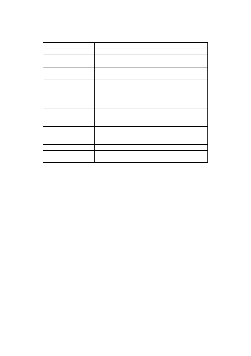
BS 5410 : part 1:
Code of practice for Oil Fired Boilers
BS 799 : part 5:
Specification for Oil Storage Tanks
BS 7593 :
Code of Practice for treatment of water in domestic hot
water central heating systems
BS 5449 : part 1:
Specification for forced circulation hot water central
heating for domestic premises.
BS EN 12828 : 2012 +
Heating systems in buildings.
A1 : 2014
Design for water – based heating systems
BS 7291 :
Thermoplastic pipes and associated fittings for hot and
cold water for domestic purposes and heating
installations in buildings
BS 7074 : part 1 :
Application, selection and installation of expansion
vessels and ancillary equipment for sealed water
systems
BS 1254 – 2 :
Copper and copper alloys plumbing fittings part 2:
Fittings with compression ends for use with copper
tubes
BS 7671 :
IET Wiring Regulations, current edition
BS 1362 :
Specification for general purpose fuse links for domestic
and similar purposes.
The Building Regulations Part G, Part J, and L1 England and Wales; Part F, Part G and
part J Section III Scotland; Part L and Part F Northern Ireland.
Local water company bye-laws.
The Control of Pollution (Oil)
Regulations. OFTEC Standards
Where no specific instructions given, reference should be made to the relevant
codes of practice.
Installation in Eire (Republic of Ireland)
The Installation will be performed by a competent and suitably trained person in
accordance with the following Eire regulations.
Current Building Regulations – Republic of
Ireland ETCI rules for electrical installation.
Page 26
Page 28
HEATESE USER GUIDE
Using the HEATESE Heating System
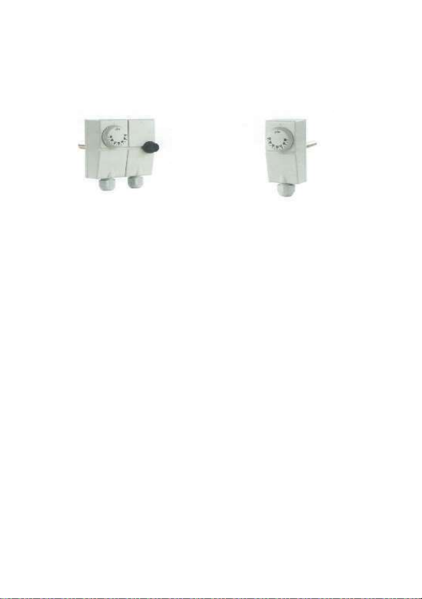
Figure 1: Control Thermostat A
Figure 2: Single Thermostat B
Please Note: A house timer has to be used, so the heating system could be turned on
or off, or could be set at the selected times for operation.
Once installed, the HEATESE Heating System is turned on and off by the house timer.
The HEATESE Heating System has two thermostats – Control Thermostat A (see
Figure 1) and Single Thermostat B (see Figure 2). To access these thermostats, there
is an access panel at the side of the enclosure or the front and the side panels of the
heating system can be removed.
At all times, these thermostats should have a 10 degree Celsius differential. This is
because the pre-warming cycle will only start delivering heating water into the
property when it reaches its set temperature at 10 degrees less than thermostat A.
Pre-warming the water in the heating system is part of the unique efficiencies of our
system, once the water has been pre-warmed, HEATESE requires a little amount of
energy to bring its temperature up to the required setting of thermostat A.
The Control Thermostat A controls the temperature of the heating water sent to the
property, this can be set by the operator to the required temperature by turning the
dial appropriately. Thermostat B should be set 10 degree Celsius lower.
Thermostat B operates a motorized valve (which is yellow in color) and controls the
pre-heating cycle. Heated water will not be circulated around the house until
thermostat B reaches the set temperature.
It will take 26approx. 10 minutes to pre-heat the heating water. This is because the
system stays warm for at least 24 hours and retains the heat internally.
Page 27
Page 29
Trip Switch
There is a white Electrical Box shown on Pg3. Inside this box you will find a
trip switch that protects the appliance. This switch should always be in the
upright position, so power could go to the appliance.
Timer
There is a time clock inside the box. This allows the dwelling pump to stay
running after the burner knocks off.
Pumps
Pump A – controls sealed system, which is always set at the lowest
circulation possible.
Pump B- circulates water throughout the dwelling. It should always be set at
the lowest circulation possible that’s suits the dwelling.
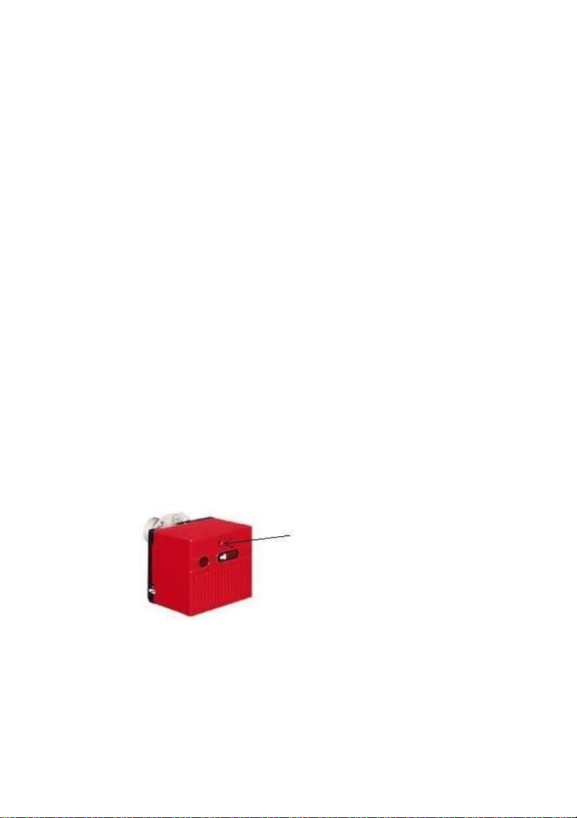
The Reset Button
At the front of the HEATESE system there is a Reillo burner (which is red in color)
and contains a reset button (See Figure 3). This button can be accessed while the
panels are in place through an inspection cover.
If the HEATESE Heating System is not working, press the reset button and the heating
system should fire. If no response, wait 2 min – press reset button again. If the lock
out light stays on, do not attempt further resets. In the event of the burner not
coming on, contact your HEATESE engineer.
The Reillo burner manual, which is supply with this manual, should be kept in a
safe place at all times.
Figure 3: The reset button on the burner
Please Note: The HEATESE will always run clean. If you notice dark smoke coming
from the chimney turn the HEATESE off and call a HEATESE engineer.
Page 28
Page 30

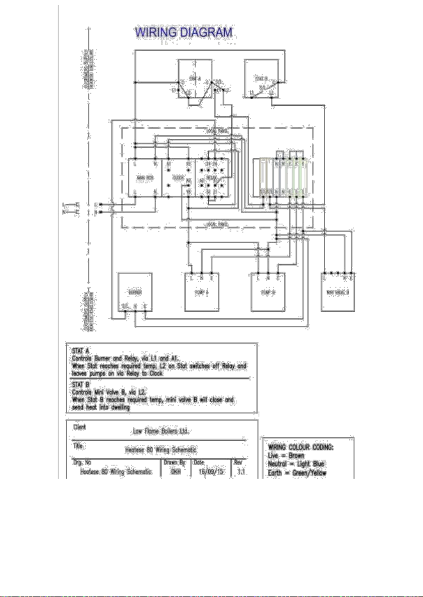
ELECTRICAL CONNECTIONS
Connections to the electrical grid
This heating system’s electrical safety is only guaranteed when correctly
connected to an efficient earthing system and executed according to
current safety standards. You must have the efficiency and suitability of
the earthing system checked by a qualified professional. The
manufacturer is not responsible for any damage caused by the failure to
earth the heating system. You must also make sure that the electrical
system is adequate for the maximum power absorbed by the unit, as
specified on the heating system data table.
The heating system is prewired and provided with a blue socket (in color)
for the connection to the electricity supply. The connections to the grid
must be made with a permanent connection. It is important to respect
polarities (LINE: brown wire. NEUTURAL: blue wire EARTH: yellow – green
wire) in making a connection to the electrical supply.
The user must never change the heating system’s power cable. If the
cable gets damaged, switch off the heating system and have it changed by
qualified professional. When changing the electric power cable, only use
“HAR H05 VV-F” 3x0.75mm2 cable with a maximum outside diameter of 8
mm.
Page 29
Page 31
Page 32

POSITIONING GUIDE
HEATESE heating system must have a solid base, that can support it’s weight.
Heating system locations and clearances
This heating system is only suitable for installation externally, outside the
property at a suitable location onto a fixed ridged surface of the same size as the
heating system and capable of supporting it’s own weight.
If the appliance is to be installed in the confined space, such as a garage, two air
vents are required, one at the high level and one at the lower level to bring air
from outside.
The heating system must be installed on a flat level surface to ensure to
condensate does not enter the primary heat exchanger.
Flue Terminal Positions
Flue terminals must be positioned to avoid combustion products entering
into buildings.
The flue must not cause an obstruction.
The flue must be fitted and terminated in accordance with the recommendations
of BS5401.
Discharge from the flue outlet must not be a nuisance.
Flue gases have a tendency to plume and in certain weather conditions white plume
of condensation will be discharged from the flue outlet which could be regarded as a
nuisance, for example, near security lighting.
There should be no restriction preventing the clearance of combustion
products from the terminal.
In order to ensure clean and efficient combustion and adequate supply of air
must be delivered to the combustion chamber.
To provide sufficient air the inlet on the front of the enclosure must be free of
all obstacles.
The heating system is not suitable for roof space installations.
Page 31
Page 33

Positioning of the HEATESE heating system – please follow these guides:
Minimum dimensions of fume exhaust terminals
A
Directly under an opening, air inlet, openable window, etc.
600mm
B
Above an opening, air inlet, openable window, etc.
300mm
C
Horizontally to an opening, air inlet, openable window, etc.
300mm
D
Under gutters, drain pipes
75mm
E
Under cornices or under eaves
200mm
F
Under balconies and garages
200mm
G
From a drain pipe or a vertical drain pipe
150mm
H
From an internal or external corner
100mm
I
Above ground level, a roof or balcony
300mm
J
From a surface facing the terminal
600mm
K
From a terminal facing the terminal
1200mm
L
From a garage opening (e.g. door, window) with access to the home
1200mm
M
Vertically from a terminal on the same wall
1500mm
N
Horizontally from the terminal on the same wall
300mm
Page 32
Page 34
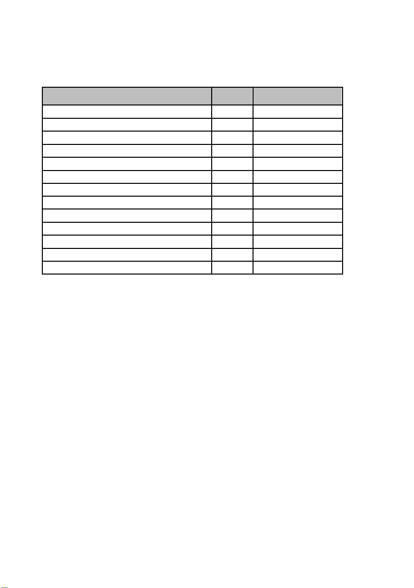
TECHNICAL DATA TABLE – HEATESE 80
Data
Unit
HEATESE 80
CH Max working pressure (sealed system)
bar
½ to 1½
CH Max working pressure Gravity feed only
CH Max temperature
o
C
90
Stat A safety limit
o
C
110
CH water content ( sealed system)
litres
30 approx.
CH water content (open vented system)
litres
110 approx.
CH expansion vessel capacity
litres
18
CH expansion vessel prefilling pressure
bar
1 to 1½
Protecting rating
IP
46
Power supply voltage
V/Hz
230V – 0.2Kw – 50Hz
Weight empty incl. pallet
kg
500 approx.
Safety Valve Operating Pressure
bar
3
86CQ35
HEATESE data label
The data label can be found on the inner wall of the enclosure directly over the red
burner on the front of the appliance.
To access the front panel remove bolts and locks, lift panel from (beneath the facia)
and remove from the appliance using the handles provided. Repeat the same action
to replace the panel and to remove the side panel – it is done in the same way.
Page 33
Page 35
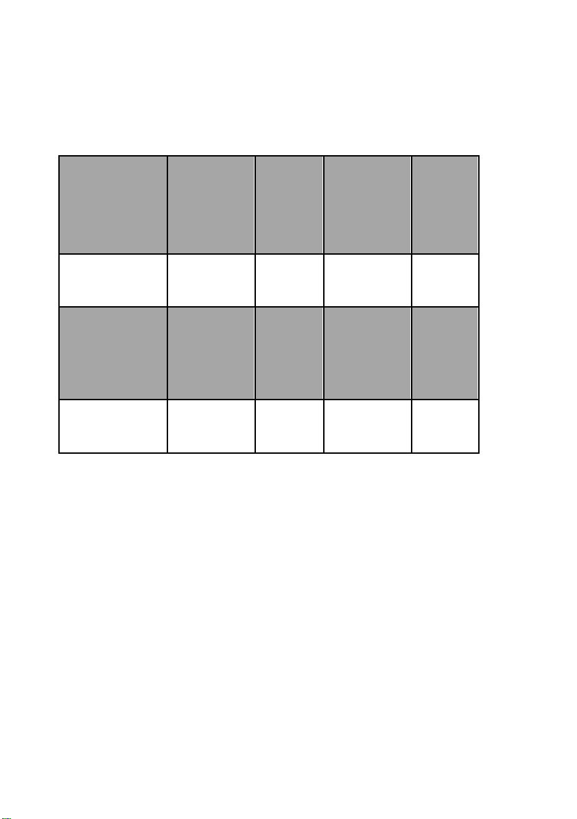
Nozzle
Oil pump
Fuel
Approx.
%CO2
pressure
flow
flue gas
(bar /psi)
rate
temp.
o
C
Kg/h
0.50x80
O
S
100 / 7.0
1.87
100
o
C
10.1
Approx air
Input(NET)
Output
Air
Burner
setting
damper
head
kW
kW
disk
setting
G3B
2.4
17.4
16.3
2.4
Part No.
3006001
Nominal heating system rating at normal operating temperature
using 28 second kerosene
G3B Burner Information
Appliance must be set to CO2 levels.
Air settings given are approximate only, as flue lent and nozzle variations will
affect this.
Page 34
Page 36
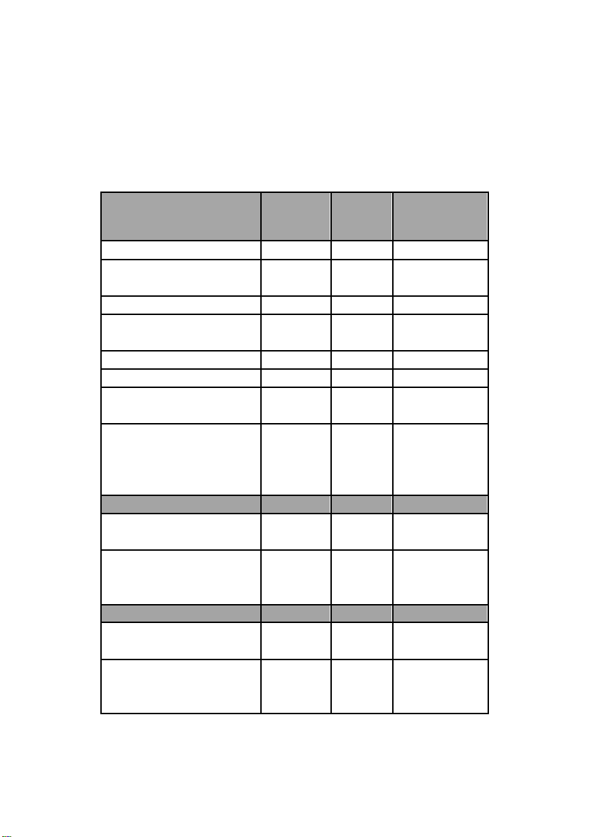
Product Data
Symbol
Unit
HEATESE
80
Condensing Heating System
-
-
Yes
Low temperature Heating
-
-
No
System
B1 Heating System
-
-
Yes
Cogeneration space heater
-
-
No
(CHP)
Combination heater
-
-
No
Rated heat output
P
rated
kW 16.3
Seasonal space heating
Ƞ
S
%
92.61
energy efficiency
Energy efficiency class
-
- A
(with class VIII
temperature
control)
Useful heat output
At rated heat output and
P4
kW 16.3
high temperature regime
1)
At 30% of rated heat output
P1
kW 17.3
and low temperature
regime
2)
Useful efficiency
At rated heat output and
Ƞ
4
% 93.8
high temperature regime
1)
At 30% of rated heat output
Ƞ1
% 99.6
and low temperature
regime
2)
The following product data satisfy the requirements of
the EU Regulations No.811/2013supplementing Directive
2010/30/EU
Page 35
Page 37
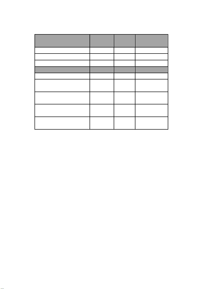
Auxiliary electricity
consumption
At full load
elmax
kW
0.100
At part load
el
min
kW
0.100
In standby mode
PSB
kW
0
Other Items
Standby heat loss
Pstby
kW
0.107
Ignition burner power
P
ign
kW
0
consumption
Emissions of nitrogen
NO
X
mg/kWh
159
oxides
(class 2,EN267)
Annual energy
QHE
kWh
N/A
consumption
Sound power level
LWA
dB(A) 68
outdoors
Product data for energy consumption
1) High temperature regime means 60
and 80oC feed temperature at heater outlet.
2) Low temperature means for condensing heating systems 30
low temperature heating systems 37oC and for other heaters 50oC
return temperature ( at heater inlet).
o
C return temperature at heater
o
C, for
Page 36
Page 38

CONVECTOR RADIATORS
Installation
The HEATESE 80 Convector Radiators must be installed by a
HEATESE engineer.
Requirements for installation:
To place the convector radiator on the wall, the front panel must be
removed by removing the white screws that are located on the top, sides
and bottom of the cabinet. On the back of the cabinet there is four
allocated frame fixing holes for placing the cabinet on the wall.
Pipework
To bring the pipework into the cabinet there are pre pressed inserts that
can be easily removed, this is to give the option for the pipework to enter
the convector cabinet, from underneath or by the side.
The flow pipe must always be connected to the left hand side of the
convector radiator. An isolating valve must be used if the heater ever
needs to be taken away without having to drain down the entire heating
system.
On the right hand side of the convector radiator the return pipe must be
connected also using an isolating valve.
Electrical connection
Inside the convector cabinet, there is a junction box. This junction box
allows the electrical installer to bring the wire from the junction box
through a prepressed insert that takes a 16mm gland. These inserts are
located on the bottom left or right hand corner of the convector
cabinet, whichever is the preferred wiring option for connecting to a
3amp fused switch.
Once all pipework and electrical connections have been completed, and
the isolating valves have been opened to let heating water into the
convector radiator, there is a bleed screw, which is located on the top
right hand side
Page 37
Page 39
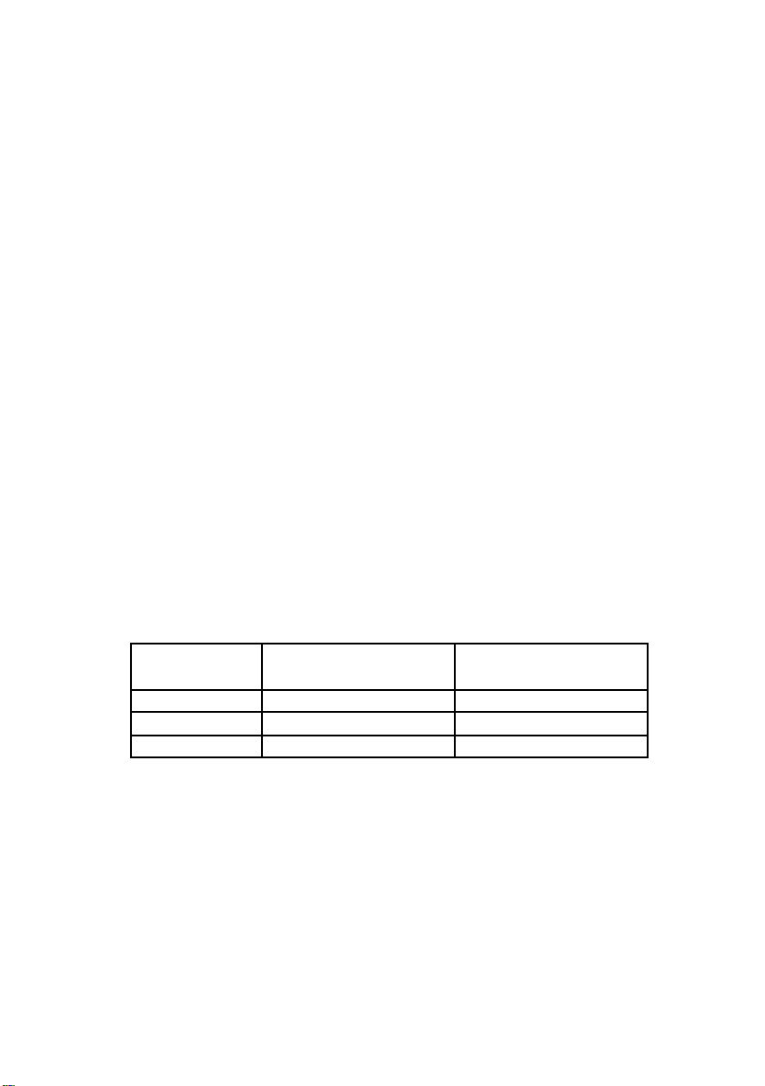
Sound [email protected]
Sound level @1m
dB(A)
dB(A)
2 Fan Unit
47.3 43.8
3 Fan Unit
48.7 46.9
4 Fan Unit
49.9 48.3
of the finned core, this screw can be slightly opened to let all air escape.
When the air bubbles stop and the water runs clear, gently tighten the
bleed screw.
Located below the bleed screw there is a pipe stat, this should always be
set at 30 oC . The reason for this is that when the HEATESE 80 heating
system sends heating water to the convector radiator, this ensures that the
fans will never operate until they reach the minimum of 30
The front cabinet door can now be replaced with the screws provided.
0
C.
Operation
To use HEATESE 80 Convector Radiator there is a room stat on the right
hand side of the unit. This stat can be adjusted to bring the room to the
desired temperature.
The HEATESE 80 heating system stat would normally be set between
55-700C. This will ensure an adequate supply of heat to the HEATESE
80 Convector Radiators.
Servicing
The HEATESE 80 Convector Radiator must be serviced with the HEATESE 80
heating system annually.
Page 38
Page 40

CONVECTOR RADIATOR WARRANTY
What is under guarantee:
1 year warranty for the finned heating core
6 year warranty for the fans
1 year warranty for the room stat
1 year warranty for the pipe stat
1 year warranty for the 12V AC/DC adaptor
Convector Radiators Electrical test passed as per EN 61010 – 1:2010
Packing materials must be kept out of reach from
children as they are potentially hazardous
Page 39
Page 41
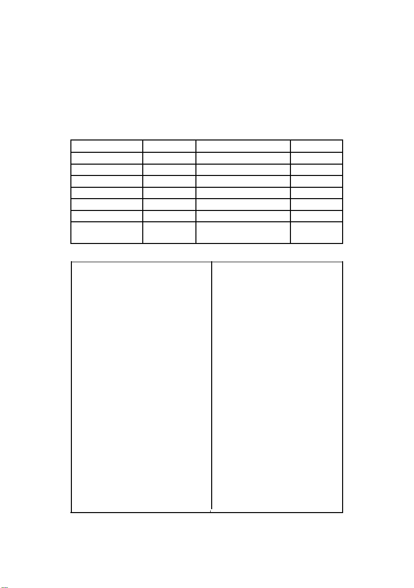
CONVECTOR RADIATOR DATA
Total output:
1.256 kw
Liquid leaving:
54.1 °C
Sensible output:
1.256 kw
Fluid pressure drop :
1584 kPa
Latent heat:
0.000 kw
Reynolds number:
120528
Air off DB:
46.0 °C
Unused tubes:
0
Air off WB:
26.4 °C
Volume:
0.190 m^3
Air pressure drop:
5 Pa
Tube weight:
0.24 kg
Air velocity:
0.91 m/s
Fin weight:
0.18 kg
Coil number:
321
Revision Date
20140812
WLHPA12:
Input
Coil Consumption
Coil Pattern No.
Lord 777 sine
Air In Wet Bulb Temp.(TWB)
-
No. of Rows Deep(ROWS)
2
19.44
0
C
Fin height(FH)
152.4mm
Air Flow(CFM)
140.2M3/H
Finned Length(FL)
280mm
Altitude/Air Pressure(P)
Altitude
No. of Circuits(CKT)
1
Value(P)
0 Meter/Bar
Number of Tubes(NT)
16
Standard Air(SA)
Standard
Tube Inserts(TB)
Bare Tube
Fluid Inlet Temp(TF)
55
0
C
Circuiting Arrangements(FLO) Counter
Fluid Number(FNO)
Water
Connections per Header(NCON)
1
Fluid Flow Rate(GPM) -
Fin Spacing(FPI)
10fpi
Calculate by Flow
Fin Material(MTL)
Aluminum
Value(GPM)
20L/Min(Delta-T0C)
Fin Thickness(FIN)
0.12mm
% Volume Glycol(PG)
0%
Number of Coils(QTY)
1
Advanced
Header Fabrication Technique(HDR) -
Fin Coating Factor(FC)
Bare Fins
Normal Header
Fin Coating Thickness(FCT)
0mm
Fluid Header Diameter(HDR)
12.7mm
Fan to Coil Position(FW)
-
Header Length(HDRL)
180mm
Coil Only( No Fan)
Tube Treatment(TT)
Smooth
Fan-Motor Position(RFW)
No Fan
Tube Wall Thickness(TW)
0.25mm
Fouling Factor Tube Side(FF) -
Connection O.D.(CON)
10mm
None
Operating Conditions
Air In Dry Bulb Temp.(TAE)
200C
HEATESE 80 – 2 FAN Water
Coil; Both – Metric units
Coil Model: 15/2x8x280/10-1 at 55
Results
0
C fluid
Page 40
Page 42
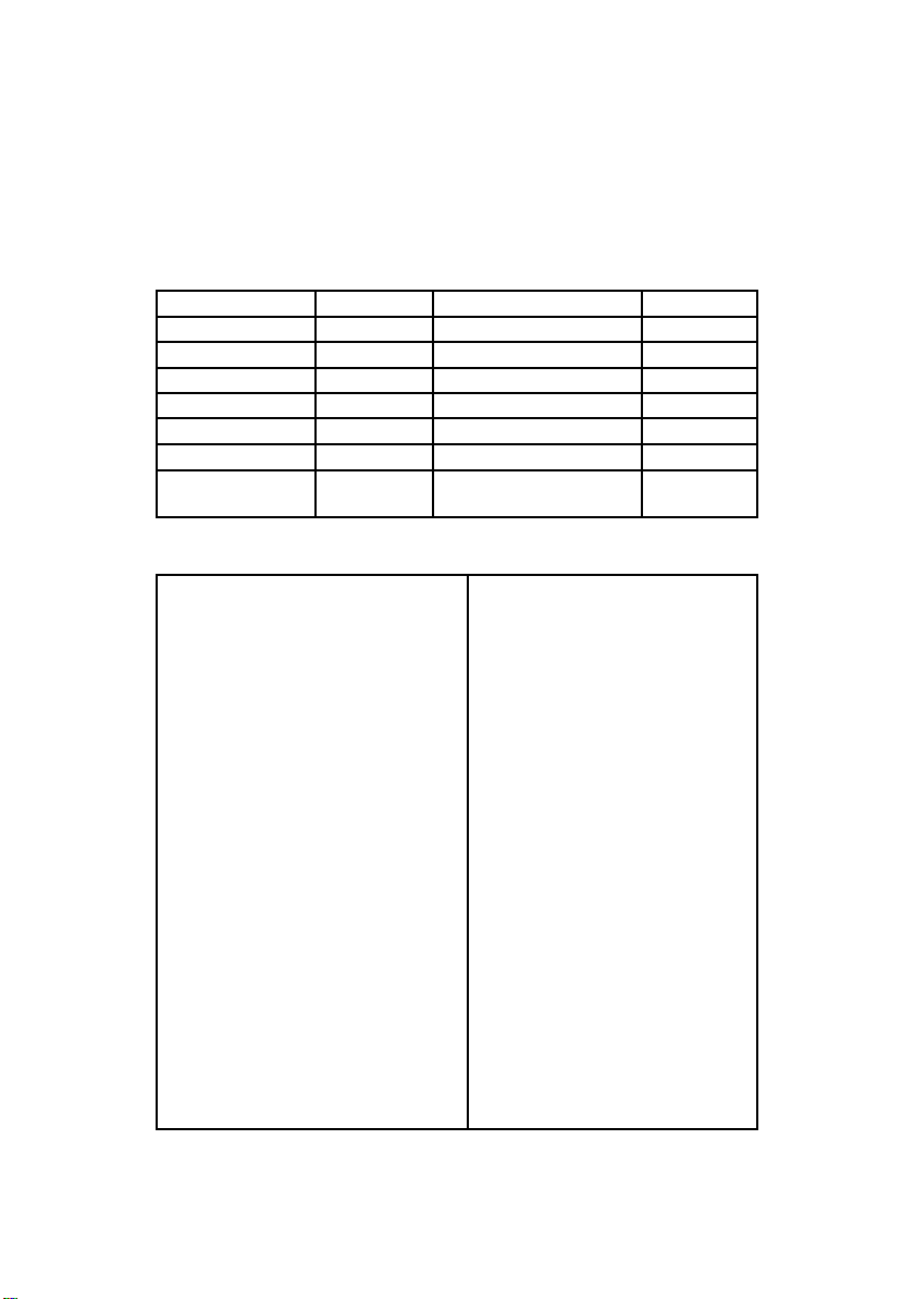
Total output:
1.436 kw
Liquid leaving:
58.9 °C
Sensible output:
1.436 kw
Fluid pressure drop :
1566 kPa
Latent heat:
0.000 kw
Reynolds number:
129845
Air off DB:
49.7 °C
Unused tubes:
0
Air off WB:
27.2 °C
Volume:
0.190 m^3
Air pressure drop:
5 Pa
Tube weight:
0.24 kg
Air velocity:
0.91 m/s
Fin weight:
0.18 kg
Coil number:
321
Revision Date
20140812
WLHPA12:
Coil Consumption
Coil Pattern No.
Lord 777 sine
Air In Wet Bulb Temp.(TWB)
-
No. of Rows Deep(ROWS)
2
19.44
0
C
Fin height(FH)
152.4mm
Air Flow(CFM)
140.2M3/H
Finned Length(FL)
280mm
Altitude/Air Pressure(P)
Altitude
No. of Circuits(CKT)
1
Value(P)
0 Meter/Bar
Number of Tubes(NT)
16
Standard Air(SA)
Standard
Tube Inserts(TB)
Bare Tube
Fluid Inlet Temp(TF)
60
0
C
Circuiting Arrangements(FLO) Counter
Fluid Number(FNO)
Water
Connections per Header(NCON)
1
Fluid Flow Rate(GPM) -
Fin Spacing(FPI)
10fpi
Calculate by Flow
Fin Material(MTL)
Aluminum
Value(GPM)
20L/Min(Delta-T0C)
Fin Thickness(FIN)
0.12mm
% Volume Glycol(PG)
0%
Number of Coils(QTY)
1
Advanced
Header Fabrication Technique(HDR) -
Fin Coating Factor(FC)
Bare Fins
Normal Header
Fin Coating Thickness(FCT)
0mm
Fluid Header Diameter(HDR)
12.7mm
Fan to Coil Position(FW)
-
Header Length(HDRL)
180mm
Coil Only( No Fan)
Tube Treatment(TT)
Smooth
Fan-Motor Position(RFW)
No Fan
Tube Wall Thickness(TW)
0.25mm
Fouling Factor Tube Side(FF) -
Connection O.D.(CON)
10mm
None
Operating Conditions
Air In Dry Bulb Temp.(TAE)
200C
Results
Input
HEATESE 80 – 2 FAN Water
Coil; Both – Metric units
Coil Model: 15/2x8x280/10-1 at 60
0
C fluid
Page 41
Page 43
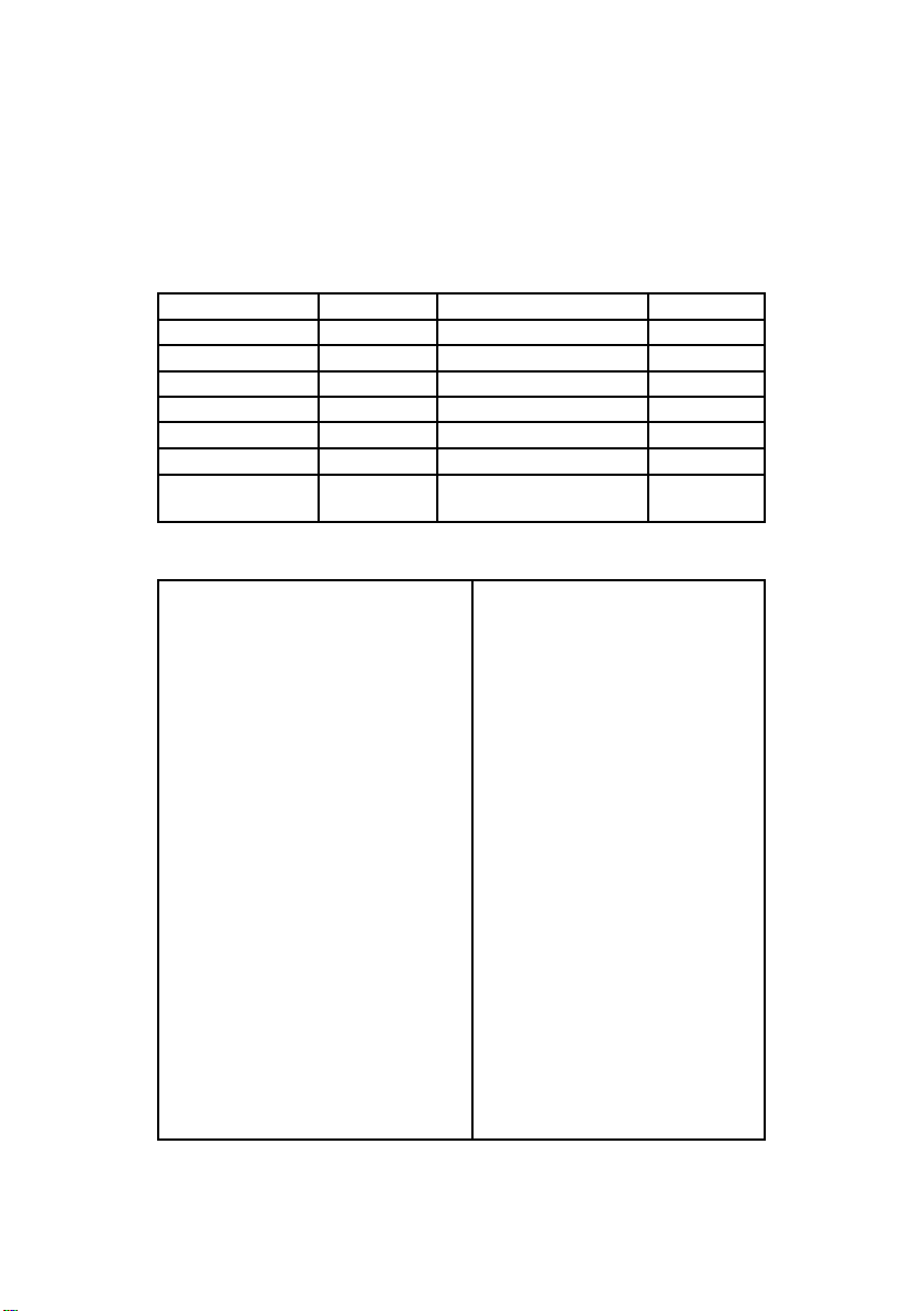
Total output:
1.616 kw
Liquid leaving:
63.8 °C
Sensible output:
1.616 kw
Fluid pressure drop :
1550 kPa
Latent heat:
0.000 kw
Reynolds number:
139284
Air off DB:
53.5 °C
Unused tubes:
0
Air off WB:
28.1 °C
Volume:
0.190 m^3
Air pressure drop:
5 Pa
Tube weight:
0.24 kg
Air velocity:
0.91 m/s
Fin weight:
0.18 kg
Coil number:
321
Revision Date
20140812
WLHPA12:
Coil Consumption
Coil Pattern No.
Lord 777 sine
Air In Wet Bulb Temp.(TWB)
-
No. of Rows Deep(ROWS)
2
19.44
0
C
Fin height(FH)
152.4mm
Air Flow(CFM)
140.2M3/H
Finned Length(FL)
280mm
Altitude/Air Pressure(P)
Altitude
No. of Circuits(CKT)
1
Value(P)
0 Meter/Bar
Number of Tubes(NT)
16
Standard Air(SA)
Standard
Tube Inserts(TB)
Bare Tube
Fluid Inlet Temp(TF)
65
0
C
Circuiting Arrangements(FLO) Counter
Fluid Number(FNO)
Water
Connections per Header(NCON)
1
Fluid Flow Rate(GPM) -
Fin Spacing(FPI)
10fpi
Calculate by Flow
Fin Material(MTL)
Aluminum
Value(GPM)
20L/Min(Delta-T0C)
Fin Thickness(FIN)
0.12mm
% Volume Glycol(PG)
0%
Number of Coils(QTY)
1
Advanced
Header Fabrication Technique(HDR) -
Fin Coating Factor(FC)
Bare Fins
Normal Header
Fin Coating Thickness(FCT)
0mm
Fluid Header Diameter(HDR)
12.7mm
Fan to Coil Position(FW)
-
Header Length(HDRL)
180mm
Coil Only( No Fan)
Tube Treatment(TT)
Smooth
Fan-Motor Position(RFW)
No Fan
Tube Wall Thickness(TW)
0.25mm
Fouling Factor Tube Side(FF) -
Connection O.D.(CON)
10mm
None
Operating Conditions
Air In Dry Bulb Temp.(TAE)
200C
Results
Input
HEATESE 80 – 2 FAN Water
Coil; Both – Metric units
Coil Model: 15/2x8x280/10-1 at 65
0
C fluid
Page 42
Page 44
Total output:
1.796 kw
Liquid leaving:
68.7 °C
Sensible output:
1.796 kw
Fluid pressure drop :
1534 kPa
Latent heat:
0.000 kw
Reynolds number:
148823
Air off DB:
57.2 °C
Unused tubes:
0
Air off WB:
28.8 °C
Volume:
0.190 m^3
Air pressure drop:
5 Pa
Tube weight:
0.24 kg
Air velocity:
0.91 m/s
Fin weight:
0.18 kg
Coil number:
321
Revision Date
20140812
WLHPA12:
Coil Consumption
Coil Pattern No.
Lord 777 sine
Air In Wet Bulb Temp.(TWB)
-
No. of Rows Deep(ROWS)
2
19.44
0
C
Fin height(FH)
152.4mm
Air Flow(CFM)
140.2M3/H
Finned Length(FL)
280mm
Altitude/Air Pressure(P)
Altitude
No. of Circuits(CKT)
1
Value(P)
0 Meter/Bar
Number of Tubes(NT)
16
Standard Air(SA)
Standard
Tube Inserts(TB)
Bare Tube
Fluid Inlet Temp(TF)
70
0
C
Circuiting Arrangements(FLO) Counter
Fluid Number(FNO)
Water
Connections per Header(NCON)
1
Fluid Flow Rate(GPM) -
Fin Spacing(FPI)
10fpi
Calculate by Flow
Fin Material(MTL)
Aluminum
Value(GPM)
20L/Min(Delta-T0C)
Fin Thickness(FIN)
0.12mm
% Volume Glycol(PG)
0%
Number of Coils(QTY)
1
Advanced
Header Fabrication Technique(HDR) -
Fin Coating Factor(FC)
Bare Fins
Normal Header
Fin Coating Thickness(FCT)
0mm
Fluid Header Diameter(HDR)
12.7mm
Fan to Coil Position(FW)
-
Header Length(HDRL)
180mm
Coil Only( No Fan)
Tube Treatment(TT)
Smooth
Fan-Motor Position(RFW)
No Fan
Tube Wall Thickness(TW)
0.25mm
Fouling Factor Tube Side(FF) -
Connection O.D.(CON)
10mm
None
Operating Conditions
Air In Dry Bulb Temp.(TAE)
200C
Results
Input
HEATESE 80 – 2 FAN Water
Coil; Both – Metric units
Coil Model: 15/2x8x280/10-1 at 70
0
C fluid
Page 43
Page 45
Total output:
1.360 kw
Liquid leaving:
54.0 °C
Sensible output:
1.360 kw
Fluid pressure drop :
355 kPa
Latent heat:
0.000 kw
Reynolds number:
60227
Air off DB:
48.2 °C
Unused tubes:
0
Air off WB:
26.9 °C
Volume:
0.263 m^3
Air pressure drop:
2 Pa
Tube weight:
0.34 kg
Air velocity:
0.60 m/s
Fin weight:
0.27 kg
Coil number:
321
Revision Date
20140812
WLHPA12:
Coil Consumption
Coil Pattern No.
Lord 777 sine
Air In Wet Bulb Temp.(TWB)
-
No. of Rows Deep(ROWS)
2
19.44
0
C
Fin height(FH)
152.4mm
Air Flow(CFM)
140.2M3/H
Finned Length(FL)
420mm
Altitude/Air Pressure(P)
Altitude
No. of Circuits(CKT)
2
Value(P)
0 Meter/Bar
Number of Tubes(NT)
16
Standard Air(SA)
Standard
Tube Inserts(TB)
Bare Tube
Fluid Inlet Temp(TF)
55
0
C
Circuiting Arrangements(FLO) Counter
Fluid Number(FNO)
Water
Connections per Header(NCON)
1
Fluid Flow Rate(GPM) -
Fin Spacing(FPI)
10fpi
Calculate by Flow
Fin Material(MTL)
Aluminum
Value(GPM)
20L/Min(Delta-T0C)
Fin Thickness(FIN)
0.12mm
% Volume Glycol(PG)
0%
Number of Coils(QTY)
1
Advanced
Header Fabrication Technique(HDR) -
Fin Coating Factor(FC)
Bare Fins
Normal Header
Fin Coating Thickness(FCT)
0mm
Fluid Header Diameter(HDR)
12.7mm
Fan to Coil Position(FW)
-
Header Length(HDRL)
180mm
Coil Only( No Fan)
Tube Treatment(TT)
Smooth
Fan-Motor Position(RFW)
No Fan
Tube Wall Thickness(TW)
0.25mm
Fouling Factor Tube Side(FF) -
Connection O.D.(CON)
10mm
None
Operating Conditions
Air In Dry Bulb Temp.(TAE)
200C
Results
Input
HEATESE 80 – 3 FAN Water
Coil; Both – Metric units
Coil Model: 15/2x8x420/10-2 at 55
0
C fluid
Page 44
Page 46
Total output:
1.555 kw
Liquid leaving:
58.9 °C
Sensible output:
1.555 kw
Fluid pressure drop :
351 kPa
Latent heat:
0.000 kw
Reynolds number:
64880
Air off DB:
52.2 °C
Unused tubes:
0
Air off WB:
27.8 °C
Volume:
0.263 m^3
Air pressure drop:
2 Pa
Tube weight:
0.34 kg
Air velocity:
0.60 m/s
Fin weight:
0.27 kg
Coil number:
321
Revision Date
20140812
WLHPA12:
Coil Consumption
Coil Pattern No.
Lord 777 sine
Air In Wet Bulb Temp.(TWB)
-
No. of Rows Deep(ROWS)
2
19.44
0
C
Fin height(FH)
152.4mm
Air Flow(CFM)
140.2M3/H
Finned Length(FL)
420mm
Altitude/Air Pressure(P)
Altitude
No. of Circuits(CKT)
2
Value(P)
0 Meter/Bar
Number of Tubes(NT)
16
Standard Air(SA)
Standard
Tube Inserts(TB)
Bare Tube
Fluid Inlet Temp(TF)
60
0
C
Circuiting Arrangements(FLO) Counter
Fluid Number(FNO)
Water
Connections per Header(NCON)
1
Fluid Flow Rate(GPM) -
Fin Spacing(FPI)
10fpi
Calculate by Flow
Fin Material(MTL)
Aluminum
Value(GPM)
20L/Min(Delta-T0C)
Fin Thickness(FIN)
0.12mm
% Volume Glycol(PG)
0%
Number of Coils(QTY)
1
Advanced
Header Fabrication Technique(HDR) -
Fin Coating Factor(FC)
Bare Fins
Normal Header
Fin Coating Thickness(FCT)
0mm
Fluid Header Diameter(HDR)
12.7mm
Fan to Coil Position(FW)
-
Header Length(HDRL)
180mm
Coil Only( No Fan)
Tube Treatment(TT)
Smooth
Fan-Motor Position(RFW)
No Fan
Tube Wall Thickness(TW)
0.25mm
Fouling Factor Tube Side(FF) -
Connection O.D.(CON)
10mm
None
Operating Conditions
Air In Dry Bulb Temp.(TAE)
200C
Results
Input
HEATESE 80 – 3 FAN Water
Coil; Both – Metric units
Coil Model: 15/2x8x420/10-2 at 60
0
C fluid
Page 45
Page 47
Total output:
1.750 kw
Liquid leaving:
63.7 °C
Sensible output:
1.750 kw
Fluid pressure drop :
348 kPa
Latent heat:
0.000 kw
Reynolds number:
64880
Air off DB:
56.3 °C
Unused tubes:
0
Air off WB:
28.6 °C
Volume:
0.263 m^3
Air pressure drop:
2 Pa
Tube weight:
0.34 kg
Air velocity:
0.60 m/s
Fin weight:
0.27 kg
Coil number:
321
Revision Date
20140812
WLHPA12:
Coil Consumption
Coil Pattern No.
Lord 777 sine
Air In Wet Bulb Temp.(TWB)
-
No. of Rows Deep(ROWS)
2
19.44
0
C
Fin height(FH)
152.4mm
Air Flow(CFM)
140.2M3/H
Finned Length(FL)
420mm
Altitude/Air Pressure(P)
Altitude
No. of Circuits(CKT)
2
Value(P)
0 Meter/Bar
Number of Tubes(NT)
16
Standard Air(SA)
Standard
Tube Inserts(TB)
Bare Tube
Fluid Inlet Temp(TF)
65
0
C
Circuiting Arrangements(FLO) Counter
Fluid Number(FNO)
Water
Connections per Header(NCON)
1
Fluid Flow Rate(GPM) -
Fin Spacing(FPI)
10fpi
Calculate by Flow
Fin Material(MTL)
Aluminum
Value(GPM)
20L/Min(Delta-T0C)
Fin Thickness(FIN)
0.12mm
% Volume Glycol(PG)
0%
Number of Coils(QTY)
1
Advanced
Header Fabrication Technique(HDR) -
Fin Coating Factor(FC)
Bare Fins
Normal Header
Fin Coating Thickness(FCT)
0mm
Fluid Header Diameter(HDR)
12.7mm
Fan to Coil Position(FW)
-
Header Length(HDRL)
180mm
Coil Only( No Fan)
Tube Treatment(TT)
Smooth
Fan-Motor Position(RFW)
No Fan
Tube Wall Thickness(TW)
0.25mm
Fouling Factor Tube Side(FF) -
Connection O.D.(CON)
10mm
None
Operating Conditions
Air In Dry Bulb Temp.(TAE)
200C
Results
Input
HEATESE 80 – 3 FAN Water
Coil; Both – Metric units
Coil Model: 15/2x8x420/10-2 at 65
0
C fluid
Page 46
Page 48
Total output:
1.945 kw
Liquid leaving:
68.6 °C
Sensible output:
1.945 kw
Fluid pressure drop :
345 kPa
Latent heat:
0.000 kw
Reynolds number:
74356
Air off DB:
60.3 °C
Unused tubes:
0
Air off WB:
29.4 °C
Volume:
0.263 m^3
Air pressure drop:
2 Pa
Tube weight:
0.34 kg
Air velocity:
0.60 m/s
Fin weight:
0.27 kg
Coil number:
321
Revision Date
20140812
WLHPA12:
Coil Consumption
Coil Pattern No.
Lord 777 sine
Air In Wet Bulb Temp.(TWB)
-
No. of Rows Deep(ROWS)
2
19.44
0
C
Fin height(FH)
152.4mm
Air Flow(CFM)
140.2M3/H
Finned Length(FL)
420mm
Altitude/Air Pressure(P)
Altitude
No. of Circuits(CKT)
2
Value(P)
0 Meter/Bar
Number of Tubes(NT)
16
Standard Air(SA)
Standard
Tube Inserts(TB)
Bare Tube
Fluid Inlet Temp(TF)
70
0
C
Circuiting Arrangements(FLO) Counter
Fluid Number(FNO)
Water
Connections per Header(NCON)
1
Fluid Flow Rate(GPM) -
Fin Spacing(FPI)
10fpi
Calculate by Flow
Fin Material(MTL)
Aluminum
Value(GPM)
20L/Min(Delta-T0C)
Fin Thickness(FIN)
0.12mm
% Volume Glycol(PG)
0%
Number of Coils(QTY)
1
Advanced
Header Fabrication Technique(HDR) -
Fin Coating Factor(FC)
Bare Fins
Normal Header
Fin Coating Thickness(FCT)
0mm
Fluid Header Diameter(HDR)
12.7mm
Fan to Coil Position(FW)
-
Header Length(HDRL)
180mm
Coil Only( No Fan)
Tube Treatment(TT)
Smooth
Fan-Motor Position(RFW)
No Fan
Tube Wall Thickness(TW)
0.25mm
Fouling Factor Tube Side(FF) -
Connection O.D.(CON)
10mm
None
Operating Conditions
Air In Dry Bulb Temp.(TAE)
200C
Results
Input
HEATESE 80 – 3 FAN Water
Coil; Both – Metric units
Coil Model: 15/2x8x420/10-2 at 70
0
C fluid
Page 47
Page 49
Total output:
1.447 kw
Liquid leaving:
53.9 °C
Sensible output:
1.447 kw
Fluid pressure drop :
389 kPa
Latent heat:
0.000 kw
Reynolds number:
60197
Air off DB:
49.9 °C
Unused tubes:
0
Air off WB:
27.3 °C
Volume:
0.348 m^3
Air pressure drop:
2 Pa
Tube weight:
0.45 kg
Air velocity:
0.45 m/s
Fin weight:
0.36 kg
Coil number:
321
Revision Date
20140812
WLHPA12:
Coil Consumption
Coil Pattern No.
Lord 777 sine
Air In Wet Bulb Temp.(TWB)
-
No. of Rows Deep(ROWS)
2
19.44
0
C
Fin height(FH)
152.4mm
Air Flow(CFM)
140.2M3/H
Finned Length(FL)
560mm
Altitude/Air Pressure(P)
Altitude
No. of Circuits(CKT)
2
Value(P)
0 Meter/Bar
Number of Tubes(NT)
16
Standard Air(SA)
Standard
Tube Inserts(TB)
Bare Tube
Fluid Inlet Temp(TF)
55
0
C
Circuiting Arrangements(FLO) Counter
Fluid Number(FNO)
Water
Connections per Header(NCON)
1
Fluid Flow Rate(GPM) -
Fin Spacing(FPI)
10fpi
Calculate by Flow
Fin Material(MTL)
Aluminum
Value(GPM)
20L/Min(Delta-T0C)
Fin Thickness(FIN)
0.12mm
% Volume Glycol(PG)
0%
Number of Coils(QTY)
1
Advanced
Header Fabrication Technique(HDR) -
Fin Coating Factor(FC)
Bare Fins
Normal Header
Fin Coating Thickness(FCT)
0mm
Fluid Header Diameter(HDR)
12.7mm
Fan to Coil Position(FW)
-
Header Length(HDRL)
180mm
Coil Only( No Fan)
Tube Treatment(TT)
Smooth
Fan-Motor Position(RFW)
No Fan
Tube Wall Thickness(TW)
0.25mm
Fouling Factor Tube Side(FF) -
Connection O.D.(CON)
10mm
None
Operating Conditions
Air In Dry Bulb Temp.(TAE)
200C
Results
Input
HEATESE 80 – 4 FAN Water
Coil; Both – Metric units
Coil Model: 15/2x8x560/10-2 at 55
0
C fluid
Page 48
Page 50
Total output:
1.654 kw
Liquid leaving:
58.8 °C
Sensible output:
1.654 kw
Fluid pressure drop :
385 kPa
Latent heat:
0.000 kw
Reynolds number:
64845
Air off DB:
54.3 °C
Unused tubes:
0
Air off WB:
28.2 °C
Volume:
0.348 m^3
Air pressure drop:
2 Pa
Tube weight:
0.45 kg
Air velocity:
0.45 m/s
Fin weight:
0.36 kg
Coil number:
321
Revision Date
20140812
WLHPA12:
Coil Consumption
Coil Pattern No.
Lord 777 sine
Air In Wet Bulb Temp.(TWB)
-
No. of Rows Deep(ROWS)
2
19.44
0
C
Fin height(FH)
152.4mm
Air Flow(CFM)
140.2M3/H
Finned Length(FL)
560mm
Altitude/Air Pressure(P)
Altitude
No. of Circuits(CKT)
2
Value(P)
0 Meter/Bar
Number of Tubes(NT)
16
Standard Air(SA)
Standard
Tube Inserts(TB)
Bare Tube
Fluid Inlet Temp(TF)
60
0
C
Circuiting Arrangements(FLO) Counter
Fluid Number(FNO)
Water
Connections per Header(NCON)
1
Fluid Flow Rate(GPM) -
Fin Spacing(FPI)
10fpi
Calculate by Flow
Fin Material(MTL)
Aluminum
Value(GPM)
20L/Min(Delta-T0C)
Fin Thickness(FIN)
0.12mm
% Volume Glycol(PG)
0%
Number of Coils(QTY)
1
Advanced
Header Fabrication Technique(HDR) -
Fin Coating Factor(FC)
Bare Fins
Normal Header
Fin Coating Thickness(FCT)
0mm
Fluid Header Diameter(HDR)
12.7mm
Fan to Coil Position(FW)
-
Header Length(HDRL)
180mm
Coil Only( No Fan)
Tube Treatment(TT)
Smooth
Fan-Motor Position(RFW)
No Fan
Tube Wall Thickness(TW)
0.25mm
Fouling Factor Tube Side(FF) -
Connection O.D.(CON)
10mm
None
Operating Conditions
Air In Dry Bulb Temp.(TAE)
200C
Results
Input
HEATESE 80 – 4 FAN Water
Coil; Both – Metric units
Coil Model: 15/2x8x560/10-2 at 60
0
C fluid
Page 49
Page 51
Total output:
1.861 kw
Liquid leaving:
63.7 °C
Sensible output:
1.861 kw
Fluid pressure drop :
381 kPa
Latent heat:
0.000 kw
Reynolds number:
69553
Air off DB:
58.6 °C
Unused tubes:
0
Air off WB:
29.1 °C
Volume:
0.348 m^3
Air pressure drop:
2 Pa
Tube weight:
0.45 kg
Air velocity:
0.45 m/s
Fin weight:
0.36 kg
Coil number:
321
Revision Date
20140812
WLHPA12:
Coil Consumption
Coil Pattern No.
Lord 777 sine
Air In Wet Bulb Temp.(TWB)
-
No. of Rows Deep(ROWS)
2
19.44
0
C
Fin height(FH)
152.4mm
Air Flow(CFM)
140.2M3/H
Finned Length(FL)
560mm
Altitude/Air Pressure(P)
Altitude
No. of Circuits(CKT)
2
Value(P)
0 Meter/Bar
Number of Tubes(NT)
16
Standard Air(SA)
Standard
Tube Inserts(TB)
Bare Tube
Fluid Inlet Temp(TF)
65
0
C
Circuiting Arrangements(FLO) Counter
Fluid Number(FNO)
Water
Connections per Header(NCON)
1
Fluid Flow Rate(GPM) -
Fin Spacing(FPI)
10fpi
Calculate by Flow
Fin Material(MTL)
Aluminum
Value(GPM)
20L/Min(Delta-T0C)
Fin Thickness(FIN)
0.12mm
% Volume Glycol(PG)
0%
Number of Coils(QTY)
1
Advanced
Header Fabrication Technique(HDR) -
Fin Coating Factor(FC)
Bare Fins
Normal Header
Fin Coating Thickness(FCT)
0mm
Fluid Header Diameter(HDR)
12.7mm
Fan to Coil Position(FW)
-
Header Length(HDRL)
180mm
Coil Only( No Fan)
Tube Treatment(TT)
Smooth
Fan-Motor Position(RFW)
No Fan
Tube Wall Thickness(TW)
0.25mm
Fouling Factor Tube Side(FF) -
Connection O.D.(CON)
10mm
None
Operating Conditions
Air In Dry Bulb Temp.(TAE)
200C
Results
Input
HEATESE 80 – 4 FAN Water
Coil; Both – Metric units
Coil Model: 15/2x8x560/10-2 at 65
0
C fluid
Page 50
Page 52
Total output:
2.068 kw
Liquid leaving:
68.5 °C
Sensible output:
2.068 kw
Fluid pressure drop :
378 kPa
Latent heat:
0.000 kw
Reynolds number:
74311
Air off DB:
62.8 °C
Unused tubes:
0
Air off WB:
29.9 °C
Volume:
0.348 m^3
Air pressure drop:
2 Pa
Tube weight:
0.45 kg
Air velocity:
0.45 m/s
Fin weight:
0.36 kg
Coil number:
321
Revision Date
20140812
WLHPA12:
Coil Consumption
Coil Pattern No.
Lord 777 sine
Air In Wet Bulb Temp.(TWB)
-
No. of Rows Deep(ROWS)
2
19.44
0
C
Fin height(FH)
152.4mm
Air Flow(CFM)
140.2M3/H
Finned Length(FL)
560mm
Altitude/Air Pressure(P)
Altitude
No. of Circuits(CKT)
2
Value(P)
0 Meter/Bar
Number of Tubes(NT)
16
Standard Air(SA)
Standard
Tube Inserts(TB)
Bare Tube
Fluid Inlet Temp(TF)
70
0
C
Circuiting Arrangements(FLO) Counter
Fluid Number(FNO)
Water
Connections per Header(NCON)
1
Fluid Flow Rate(GPM) -
Fin Spacing(FPI)
10fpi
Calculate by Flow
Fin Material(MTL)
Aluminum
Value(GPM)
20L/Min(Delta-T0C)
Fin Thickness(FIN)
0.12mm
% Volume Glycol(PG)
0%
Number of Coils(QTY)
1
Advanced
Header Fabrication Technique(HDR) -
Fin Coating Factor(FC)
Bare Fins
Normal Header
Fin Coating Thickness(FCT)
0mm
Fluid Header Diameter(HDR)
12.7mm
Fan to Coil Position(FW)
-
Header Length(HDRL)
180mm
Coil Only( No Fan)
Tube Treatment(TT)
Smooth
Fan-Motor Position(RFW)
No Fan
Tube Wall Thickness(TW)
0.25mm
Fouling Factor Tube Side(FF) -
Connection O.D.(CON)
10mm
None
Operating Conditions
Air In Dry Bulb Temp.(TAE)
200C
Results
Input
HEATESE 80 – 4 FAN Water
Coil; Both – Metric units
Coil Model: 15/2x8x560/10-2 at 70
0
C fluid
Page 51
Page 53
HEATESE 80 HEATING SYSTEM FAULT FINDING
Problem
Couse
Remedy
Heating stays on for too long
Clock is incorrectly set
Check settings and adjust
Hot water temperature is too
Temperature is set too low on
Check settings and adjust
low
heating system
Desired room temperature is
Check convector radiators
Turn up convector radiator room
not reached
room stats
stat
Hot water temperature is too
Check thermostat on heating
Check settings and adjust
high
system
Burner motor fails to operate
Faulty motor or electrical
Check for 230V to motor during
supply to motor.
start up period.
Control box fault
Replace control box
Flame detection fault
Photocell filmed over(dirty)
Wipe clean
Photocell faulty
Replace
Control box faulty
Replace
Incorrect CO2
Air adjustment fault
Set up as shown in Data Table
Oil pressure incorrect
Set up as shown in Data Table
No oil from nozzle
No oil at pump
Check and refill oil tank/bleed oil
line. Check and clean filters and
valves from oil tank to heating
system.
Air in pump Nozzle
Bleed pump
blocked Faulty pump
Replace nozzle
or drive
Replace
GUIDE
In the event the appliance stops functioning or does not perform as expected,
you can carry out few simple checks. These checks are some of the common
causes are listed in the table below.
Should the problem persist, please contact your HEATESE engineer.
Under no circumstances must an appliance be left to operate
with any control linked out or overridden.
Page 52
Page 54
Ignition failure
Faulty ignition transformer
Replace
Open circuit ignition
Check and replace electrodes if
necessary
Faulty control box or
Correct electrical control box
electrical connections not
connections or replace control
properly made
box
Burner fails to start
No power to heating system
Check electrical control unit
located in white cabinet
Faulty heating thermostats
Check the temporarily linking out
high limit and control thermostats
Noisy operation
Pump noise from air in pump
Bleed air from pump or replace
or warn pump
pump Replace
Fan out of balance
fan Replace
Worn motor bearings
motor
Boiling
Faulty heating thermostat
Replace if necessary
No primary water circulation
Check system/circulation pump
Short cycling
Burn rating incorrect
Correct burner rating
Heating thermostat
Replace heating thermostat
differential incorrect
External controls not
Check and correct external
operating correctly
controls located in white cabinet
Oil smells
Blocked flue, fumes on start
Check flue with gauge and check
up
seals/gaskets
Oil soaked heating system,
Rectify burner operation and lock
faulty burner operation,
outs
numerous lock outs
Odour in enclosure, oil leak
Rectify oil leaks, replace
from pipework, flexible hose
components if necessary
connection
Page 53
Page 55

HEATESE PRE- COMMISIONING CHECKLIST
This commissioning Checklist is to be completed in full by the
competent person who commissioned the heating system as a means
of demonstrating compliance with the appropriate Building Regulations
and then handed to the customer to keep for future reference.
The engineer should set up the controls and show the customer how to
operate all the controls shown in the user guide plus any external controls.
Show the customer the fault finding information in this user guide. Show the
customer where the serial number/ appliance information is.
Failure to install and commission according to the manufacturer’s instructions
and complete this Benchmark Commission Checklist will invalidate the
warranty. This does not affect the customer’s statutory rights.
Check that the service and water pipes are connected correctly.
Check that the oil supply is Class C2, 28 second Kerosene and
that the pipe work is connected correctly to the oil filter.
Turn on the main supply valve at the tank, check the oil
supply pipework and connections. Rectify any leaks.
Check the flue is correctly fitted and connections are secure.
Check the condensate pipework is correctly fitted and
connected. Check the condensate trap is filled with water.
Page 54
Page 56

Heating system details
Commissioning Checks
Oil Type Used is Kerosene
Yes
Pump Pressure
PSI
CO2 % CO
ppm CO/CO2 ratio
Smoke Reading
Flue Gas Temperature
o
C
Flue Pressure
Burner Model
heating system manufacturer’s instructions
Yes
What system cleaner was used?_
Page 55
Make and Model_
Serial Number
Commissioning Engineer
Company Name
Company Address
Telephone Number_
Commissioned by (signature)
Commissioning Date_
(print name)_
All Systems
The system has been flushed and cleaned in accordance with BS7593 and
Page 57

What inhibitor was used?
Quantity
litres
Has a system filter been fitted?
Yes
No
The condensate drain has been installed in accordance with the
manufacturer’s instructions and /or BS5546/BS6798
Yes
the manufacturer’s instructions?
Yes
No If the condensate pipe terminates externally has the pipe diameter been
increased and weatherproof insulation fitted?
Yes
All Installations
Does the installation comply with the current OFTEC Regulations?
Yes
No
Regulations
Yes
No
The heating system and associated products have been installed and
commissioned in accordance with the manufacturer’s instructions
Yes
No
The Class VII temperature control stat has been installed in accordance with
The heating and hot water system complies with the appropriate Building
The operation of the heating system controls have been
demonstrated to and understood by the customer Yes No
Page 56
Page 58

SERVICE RECORD
Service 1
Date
Engineer Name
Company Name
Telephone No._
Authorized Register No._
Nozzle Changed?
Yes
No
Pump Pressure
psi CO2
%
CO
ppm
CO/CO2 ratio
F.G.T._
0
C
Flue Pressure
Comments:_
Signature
Service 2
Date
Engineer Name
Company Name
Telephone No._
Authorized Register No._
Nozzle Changed?
Yes
No
Pump Pressure
psi
CO2
%
CO
ppm
CO/CO2 ratio
F.G.T._
0
C
Flue Pressure
Comments:_
Signature
Service 3
Date
Engineer Name
Company Name
Telephone No._
Authorized Register No._
Nozzle Changed?
Yes
No
Pump Pressure
psi CO2
%
CO
ppm
CO/CO2 ratio
F.G.T._
0
C
Flue Pressure
Comments:_
Signature
Page 57
Page 59

SERVICE RECORD
Service 1
Date
Engineer Name
Company Name
Telephone No._
Authorized Register No._
Nozzle Changed?
Yes
No
Pump Pressure
psi CO2
%
CO
ppm
CO/CO2 ratio
F.G.T._
0
C
Flue Pressure
Comments:_
Signature
Service 2
Date
Engineer Name
Company Name
Telephone No._
Authorized Register No._
Nozzle Changed?
Yes
No
Pump Pressure
psi
CO2
%
CO
ppm
CO/CO2 ratio
F.G.T._
0
C
Flue Pressure
Comments:_
Signature
Service 3
Date
Engineer Name
_
Company Name
Telephone No._
Authorized Register No._
Nozzle Changed?
Yes
No
Pump Pressure
psi CO2
%
CO
ppm
CO/CO2 ratio
F.G.T._
0
C
Flue Pressure
Comments:_
Signature
Page 58
Page 60

SERVICE RECORD
Service 1
Date
Engineer Name
Company Name
Telephone No._
Authorized Register No._
Nozzle Changed?
Yes
No
Pump Pressure
psi
CO2
%
CO
ppm
CO/CO2 ratio
F.G.T._
0
C
Flue Pressure
Comments:_
Signature
Service 2
Date
Engineer Name
Company Name
Telephone No._
Authorized Register No._
Nozzle Changed?
Yes
No
Pump Pressure
psi
CO2
%
CO
ppm
CO/CO2 ratio
F.G.T._
0
C
Flue Pressure
Comments:_
Signature
Service 3
Date
Engineer Name
Company Name
Telephone No._
Authorized Register No._
Nozzle Changed?
Yes
No
Pump Pressure
psi CO2
%
CO
ppm
CO/CO2 ratio
F.G.T._
0
C
Flue Pressure
Comments:_
Signature
Page 59
Page 61

HEATESE CONTACT NUMBERS
Phone numbers:
Installer
.
Service Engineer
.
Before contacting HEATESE please have available the completed Benchmark document
(located inside this manual), heating system, serial number and model detail.
For Technical assistance during the installation, call our Technical Helpline on 086
2438990
Should you require a Service Engineer to visit, call our Service Centre on 086 2438990
Details may vary slightly from those quoted in these instructions.
HEATESE Partner to Low Flame Boilers Ltd
Please note – to avoid incurring unnecessary expense, in the event of a heating
system shut down, check that it is not caused by lack of electricity supply and / or a
lack of oil supp ly before calling our Customer Service Helpline.
Page 60
 Loading...