

Page 1

405 E. Santa Clara St.
Arcadia, CA 91006-7218
Tel: (626) 599-8566 Fax: (626) 599-9567
FLUIDIX
Ultra-Pure D.I. WATER
HEATING SYSTEM
World Leaders in Ultra-Pure Heating Revision 10
www.heateflex.com 01/17/13
SERIES
Page 2

405 E. Santa Clara St.
Arcadia, CA 91006-7218
Tel: (626) 599-8566 Fax: (626) 599-9567
World Leaders in Ultra-Pure Heating Revision 10
www.heateflex.com 01/17/13
Page 3

405 E. Santa Clara St.
Arcadia, CA 91006-7218
Tel: (626) 599-8566 Fax: (626) 599-9567
INDEX
Section I – Fluidix Instruction Manual
Table of Contents
Preface
Theory of Operations
System Control
Safety Systems
Preventive Maintenance and Servicing
Installation and Start-up Procedures
Servicing Policies
Section II - APPENDIX
Touch Screen Displays
External Flow Sensors
Temperature Dead Band Signal
Equipment Specification
Factory Default Parameters
Quality Assurance Checklist
Pressure Relief Valve Calibration
Drawings
Flow Meter Configuration Document
Parameter Log
Ethernet Communications
Instruction Manual Revisions
ASME Data Report (if applicable)
World Leaders in Ultra-Pure Heating Revision 10
www.heateflex.com 01/17/13
Page 4

405 E. Santa Clara St.
Arcadia, CA 91006-7218
Tel: (626) 599-8566 Fax: (626) 599-9567
TABLE OF CONTENTS
Section I
1.0 General Information
1.1 Introduction
2.0 Theory of Operation
2.1 System Overview
2.2 How the Process is Heated
2.3 How the Temperature is Controlled
2.4 Ancillary Systems
3.0 System Control
3.1 Temperature-Control Overview
3.1.1 Temperature-Control Specifics
3.2 Touch-Screen Display
3.2.1 Main Menu
3.2.2 System Status
3.2.3 Recalibration
3.2.4 Temperature Trending
3.2.5 Alarm Menu and Alarm Screens
3.2.6 Date and Time Set Up
3.2.7 Alarm History
3.3 The Remote Control Panel
3.4 Input/Output Functions
4.0 Safety Systems
4.1 Overview
4.2 Shellside (Steam) Safety Mechanisms
4.2.1 Shellside Over-Pressure
4.2.2 Shellside Over-Temperature
4.3 Tube Side (Process) Safety Mechanisms
4.3.1 Process Over-Temperature
4.3.2 Process Over Pressure
4.3.3 Low Process Pressure
4.3.4 Low Process Temperature
4.3.5 Hot Valve Over-Temperature
4.3.6 Low D.I. Flow Rate
4.4 Auto-Isolation System
4.4.1 Loss of D.I. Water Line Pressure/Auto Isolation
4.5 Shellside/Vessel Flooding
4.6 Water Leak
4.7 Summary of Alarm Conditions and System Reponses
4.8 Use of Emergency Off (EMO) Switch
4.9 Door Interlock
World Leaders in Ultra-Pure Heating Revision 10
www.heateflex.com 01/17/13
Page 5

405 E. Santa Clara St.
Arcadia, CA 91006-7218
Tel: (626) 599-8566 Fax: (626) 599-9567
TABLE OF CONTENTS
5.0 Preventative Maintenance and Servicing
5.1 Process Control System
5.1.1 Thermocouple Temperature Sensors
5.1.2 Temperature Switches
5.1.3 Pressure Transducer
5.1.4 Flow Sensor
5.2 Process Exchanger Mechanicals
5.2.1 Repairing a Tube Failure
5.2.2 Repairing a Leaking Fitting
5.2.3 The Mixing Valves
6.0 Installation and Start-up Procedures
6.1 Facilities Hook-Up
6.2 Initial Heat-Up
6.3 Adjusting Temperature Control Parameters
7.0 Servicing Policies
7.1 Self Service
7.2 Factory Service
7.3 Warranty
Section II
8.0 Appendix
8.1 Important Touch Screen Notes
8.2 Touch Screen Displays
8.2.1 Main Menu
8.2.2 Date/Time Set Up
8.2.3 System Status
8.2.4 Recalibration
A. Recalibration Instructions
B. Factory Adjustable Parameters Menu
C. Factory Adjustable Parameters
D. Temperature Dead Band
8.2.5 Temperature Control Trending
8.2.6 Alarm Menu
A. D.I. Pressure Relief Venting Alarm
B. D.I. Pressure Relief Venting Diagnostic Information
C. Hot Valve Over Temperature Alarm
D. Hot Valve Over Temperature Diagnostic Information
E. Low Flow Rate Alarm
F. Low Flow Rate Diagnostic Information
G. Low Process Pressure Alarm
H. Low Process Pressure Diagnostic Information
World Leaders in Ultra-Pure Heating Revision 10
www.heateflex.com 01/17/13
Page 6

405 E. Santa Clara St.
Arcadia, CA 91006-7218
Tel: (626) 599-8566 Fax: (626) 599-9567
TABLE OF CONTENTS
I. Low Process Temperature Alarm
J. Low Process Temperature Diagnostic Information
K. Process Over Temperature Alarm
L. Process Over Temperature Diagnostic Information
M. Shellside Over Temperature Alarm
N. Shellside Over Temperature Alarm Diagnostic Information
O. Steam Pressure Relief Venting Alarm
P. Steam Pressure Relief Venting Diagnostic Information
Q. Vessel Flooding Alarm
R. Vessel Flooding Diagnostic Information
S. Water Leak Alarm
T. Water Leak Diagnostic Information
8.2.7 Alarm History
8.2.8 External Flow Sensor
8.3 Pressure Relief Valve Calibration Procedure
8.4 Quality Control Documentation
8.4.1 Equipment Specifications
8.4.2 Fluidix PC Factory Default Parameters
8.4.3 Fluidix Ultra-Pure D.I. Water Heating System Quality Assurance
Checklist
8.4.4 Freescale Fluidix Source Inspection
8.4.5 Flow Meter Configuration
8.5 Drawings
8.5.1 Facility Connections
8.5.2 Mechanical Drawing
8.5.3 Plumbing Diagram
8.5.4 Electrical Component Layout
8.5.5 Electrical Schematics
8.6 Parameter Log
8.6.1 Generic
8.7 Ethernet Communications
8.7.1 Ethernet System Values & Set Points
8.7.2 Ethernet System Status & Alarms
8.8 Manual Revisions
8.9 ASME Data Report (if applicable)
World Leaders in Ultra-Pure Heating Revision 10
www.heateflex.com 01/17/13
Page 7

405 E. Santa Clara St.
Arcadia, CA 91006-7218
Tel: (626) 599-8566 Fax: (626) 599-9567
Section I
Instruction
Manual
World Leaders in Ultra-Pure Heating Revision 10
www.heateflex.com 01/17/13
Page 8

405 E. Santa Clara St.
Arcadia, CA 91006-7218
Tel: (626) 599-8566 Fax: (626) 599-9567
World Leaders in Ultra-Pure Heating Revision 10
www.heateflex.com 01/17/13
Page 9

405 E. Santa Clara St.
Arcadia, CA 91006-7218
Tel: (626) 599-8566 Fax: (626) 599-9567
1.0 General Information
_________________________________________________________
1.1 Introduction
Thank you for your purchase of the Fluidix D.I. Water Heating System. We have strived in the
engineering and redesign of the Fluidix D.I. Water Heating System to provide you with a
product that has quality, performance, reliability, serviceability, and safety. Further, it is our
goal to support you, the customer, and the equipment in as positive and professional a manner
as possible.
This manual serves as a guide to how the unit is designed and how it is to be properly operated
for maximum performance and safety. It is strongly recommended that you and others who
will work with the unit read the entire manual prior to the use of the system. It is our
recommendation that the manual be kept readily available to others who may later need to refer
to it.
Another feature of this manual is the sections dealing with servicing. We realize that the
competitive business in which this equipment will be used is very sensitive to production
downtime. One of the prime considerations in the engineering of all Fluidix systems is the
feature of user serviceability. This philosophy of user serviceability has not been designed to
shift the servicing responsibility to the customer, but rather to give the customer the servicing
capability to react quickly to virtually any possible issue that may occur. This ability allows
you to have greater control over your production environment and to have one more weapon to
preclude lengthy downtimes. We are confident that if the instructions for the proper operation
and maintenance of the system are followed the unit will have years of trouble free service.
Please read the manual carefully: the system is not difficult to operate, but does require some
detailed understanding in order for it the unit to properly function. Feel free to call Heateflex
Corporation with any questions regarding start-up or maintenance.
World Leaders in Ultra-Pure Heating Revision 10
www.heateflex.com 01/17/13
Page 10

405 E. Santa Clara St.
Arcadia, CA 91006-7218
Tel: (626) 599-8566 Fax: (626) 599-9567
2.0 Theory of Operation
__________________________________________________________
2.1 System Overview
The Fluidix PC Series D.I. Water Heating System combines a steam-powered PFA heat
exchanger with a process temperature-control system to provide a "turn-key" D.I. waterheating system.
All wetted surfaces are virgin PVDF, PFA and PTFE with elastomeric PTFE for piping seals
for no measurable change in TOC, particles ≥0.06µ or bacteria, and less than 0.1 ppb ionic
contamination from the process inlet to the process outlet. Each system is computer designed
to ensure sufficiently high water velocity to prevent bacteria growth, particularly in the inlet
region of exchanger tubing where the water is warm but not yet sufficiently hot to kill the
bacteria. During a period of low or no flow, the D.I. water in the tubing quickly rises to
sterilization temperatures.
The exchanger is a kettle-type configuration with a PFA tube bundle wound helically around a
central support, which is mounted to the exchanger cover. Removal of this exchanger cover
gives complete access to the Fluidix tube bundle for inspection of all its components. The
vessel and its cover comprise a pressurized system where steam is introduced through a
flanged inlet mounted at the side of the exchanger vessel, and where steam condensate is
drained at the bottom.
The exchanger bundle utilizes a sanitary head design such that continuous lengths of tubing
pass through the vessel cover and connect to pipe headers above the exchanger cover (See
Appendix). This configuration provides that there are no welds or connections in the tubing
within the exchanger vessel, which could potentially leak. If a tube fitting on a pipe header
develops a leak, it can be easily accessed and tightened after the unit is cooled down.
Temperature control, independent of flow rate, is accomplished by means of two mixing
valves, which blend ambient-temperature water with the hot exchanger effluent water to yield
the desired output temperature. A thermocouple temperature sensor monitors the outlet
temperature whose signal along with that of a shedding-vortex flow meter is then used by the
PLC controller to position the mixing valves as needed.
World Leaders in Ultra-Pure Heating Revision 10
www.heateflex.com 01/17/13
Page 11

405 E. Santa Clara St.
Arcadia, CA 91006-7218
Tel: (626) 599-8566 Fax: (626) 599-9567
_________________________________________________________
2.2 How the Process is Heated
The heating system receives its heating power from <15 psig regulated steam supply. This
steam comprises the shellside-heating medium and completely surrounds the tube bundle
inside the pressure vessel. The steam flow into the vessel is not throttled as it is "selfcontrolling". As the flow of process water inside the exchanger tubing increases or decreases,
the rate of condensation of the steam on the outside of the tubing also increases and decreases
proportionally. In the case where the flow of process water stops completely, the tubing and
process water equilibrate to the same temperature as the steam, condensation ceases, and steam
flow into the vessel ceases.
__________________________________________________________
2.3 How the Temperature is Controlled
The PC series D.I. water heating system utilizes a "mixing-valve" temperature-control system
which can deliver unmatched accuracy in output temperature, independent of the most extreme
variations in D.I. water flow rate.
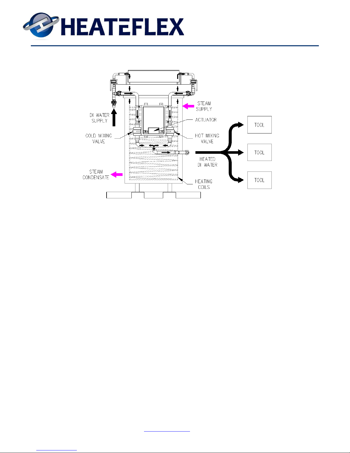
D.I. water is heated in the Fluidix PFA heat exchanger to above the set point temperature and is
continuously blended in varying ratios with ambient-temperature D.I. water by means of two
PVDF mettering valves to yield the desired set point temperature. The two mixing valves are
positioned 90° from one another (one is fully open when the other is fully closed) and are
driven by a common actuator such that a 90° rotation of the actuator can produce output
temperatures anywhere from ambient to near the steam inlet temperature.
The control system uses a look-up table, which is calibrated initially at start-up, to give the
proper actuator position as a function of set point temperature and flow rate. This type of
control provides immediate adjustment in the hot / cold blending ratio over the fast changes in
flow rate associated with many semiconductor- process tools. Once the flow rate re-stabilizes,
the control system also provides a “trimmer” function to make small adjustments in the
actuator position to fine tune.
The following figure shows the basic schematic of the process components. The exchanger is
actually broken down into two or more parallel tube bundles each fitted with isolation valves
and two pressure relief valve systems (steam and D.I.), which are not shown in this simplified
diagram.
World Leaders in Ultra-Pure Heating Revision 10
www.heateflex.com 01/17/13
Page 12
405 E. Santa Clara St.
Arcadia, CA 91006-7218
Tel: (626) 599-8566 Fax: (626) 599-9567
The overall pressure drop across the system remains nearly constant, regardless of the position
of the mixing valves, due to the fact that as one of the mixing valves is opening, the other is
closing, so the combined cross-sectional area of the two valves is essentially constant.
__________________________________________________________
2.4 Ancillary Systems
The PC series D.I. water heating systems are offered with two optional systems: the AutoIsolation System and the Auto-Shutdown System.
The Auto-Shutdown System is used to close the steam supply valve to the unit based on
various conditions, which could harm the unit or downstream piping and equipment.
The Auto-Isolation System is used to close two isolation valves, one upstream and one
downstream of the unit, based on various conditions which could lead to a potential
contamination of the process water.
These two ancillary systems are discussed in detail in Section 4.0
World Leaders in Ultra-Pure Heating Revision 10
www.heateflex.com 01/17/13
Page 13

405 E. Santa Clara St.
Arcadia, CA 91006-7218
Tel: (626) 599-8566 Fax: (626) 599-9567
3.0 System Control
__________________________________________________________
3.1 Temperature-Control Overview
The temperature and flow of the D.I. water is monitored by a thermocouple and shedding
vortex flow meter, respectively. These signals are inputted to the programmable logic
controller (PLC), the values of which are indicated on the touch-screen display.
The flow signal, along with the set point temperature are used as inputs to a look-up table
which outputs the proper actuator position for the hot and cold mixing valves to yield the
desired set point temperature.
At any given flow rate, there is a specific mix-ratio of hot D.I. water exiting the heat
exchanger, blended with ambient-temperature water from a bypass line, which will yield the
proper set point temperature. These values are programmed into the PLC‟s look-up table.
When there is a sufficient change in flow rate, as sensed by the flow meter, the PLC
immediately causes the actuator, which positions the mixing valves, to move to the new value
listed in the look-up table. This response to the change in flow rate is immediate without
waiting until there is a detected deviation from set point for the process temperature as with
conventional temperature control systems.
Additionally, the PLC has a trimmer function, which is based on the temperature sensor at the
outlet of the unit to make small adjustments in the actuator position to fine tune the unit.
__________________________________________________________
3.1.1 Temperature-Control Specifics
Temperature control is a function of two inputs, D.I. Flow Rate and D.I. Temperature,
compared with the set point temperature. If the actual D.I. temperature is within ±1°C of set
point, the actuator will maintain its current position and the look-up table will not be consulted,
nor will the trimmer function make further adjustments. If the actual temperature is not within
that range, then one of two things will happen.
First, the PLC does a comparison on flow rates. If the flow rate has change by a specified
value of ±1 GPM (Factory Default) or more, then the look-up table is consulted for the proper
actuator position corresponding to the new flow rate. (This 1 GPM value can be field adjusted
during start-up as necessary depending on the actual process flows.)
If the flow rate has not changed more than ±1 GPM, and the D.I. temperature is not within
±1°C, then a trimmer function takes over. This function checks to see if the temperature is
within the desired range, and if not, the actuator is adjusted slightly to a new position. After a
specified time interval, the temperature is checked again and the actuator moves another small
World Leaders in Ultra-Pure Heating Revision 10
www.heateflex.com 01/17/13
Page 14

405 E. Santa Clara St.
Arcadia, CA 91006-7218
Tel: (626) 599-8566 Fax: (626) 599-9567
increment if needed. This process is repeated until the temperature is within ±1°C of the
specified set point. The amount of each incremental actuator movement and the specified time
between readings is user adjustable in the Recalibration screen. The time intervals are set to be
just longer than the response time for the temperature to stabilize after a move of the actuator,
typically 5 to 10 seconds.
__________________________________________________________
3.2 Touch-Screen Display
The Omron, Touch-Screen Display mounted on the front panel of the electrical enclosure is the
user interface for the unit. When the unit is powered up, the Main Menu screen will appear
with buttons to access additional screens such as the System Status screen. The System Status
screen is the main informational screen and contains the current status of the unit, as well as
touch switches for operating actuated valves and performing other functions on the unit.
Moving from screen to screen and setting switches is a simple matter of touching the surface of
the display in the area of the screen indicated. For example, pressing the box on the display
labeled “MAIN MENU” would return the display to the main menu, and pressing the box
labeled “OPEN” would open the steam valve on the unit.
The ability to operate or change any settings to the unit via the touch-screen display is
password protected to prevent unauthorized personnel from access. There are two types of
passwords, the “operational password” and the “administrative password”. The “operational
password” is located on the Main Menu screen. The “operational password” is actually two
simultaneous keystrokes; the first is located in the area above the “PRESS FOR SYSTEM
STATUS” button or to the left of the “DATE” label and the second is located above the
“PRESS FOR TEMP TRENDING” button and to the right of the “TIME” label. When these
two areas are depressed, the “operational password” will activate and then operation functions
can be made in any of the screens for a period of fifteen minutes, after which the lockout will
automatically reset. The actual position for the operational password is indicated in the
Appendix. The “administrative password” allows access to changing controller parameters,
setting the date or time, and modifying alarm set points/delay timers.
In order to enhance the lifetime of the electroluminescent screen a screen saver function is
available which will darken the screen if there is no activity for a period of ten minutes.
Touching any area on the display will return the screen to normal, illuminated operation.
Pictures of all touch-screen displays are shown in the appendix of this manual.
World Leaders in Ultra-Pure Heating Revision 10
www.heateflex.com 01/17/13
Page 15

405 E. Santa Clara St.
Arcadia, CA 91006-7218
Tel: (626) 599-8566 Fax: (626) 599-9567
__________________________________________________________
3.2.1 Main Menu
The Main Menu consists of six screen switches for the parent screen in each area of the control
system; System Status, Recalibration, Temperature Control, Alarm Menu, and Alarm History,
and External Flow. By touching one of these buttons, you will move to the respective screen.
In addition, the date and time set up buttons are located on this screen (see Section 3.2.6 for
more information).
Please note that an alarm will automatically trigger upon initial start up of the unit. The
“ALARM RESET” button must be pressed prior to the operation of the unit.
__________________________________________________________
3.2.2 System Status
This screen displays the current status of the unit and allows manual overrides of the AutoIsolation and Auto-Shutdown valves. It has an audio-alarm defeat (“ENABLE AUDIO” /
“DISABLE AUDIO”) and an alarm reset function (“ALARM RESET”).
Displayed on the screen are the D.I. Temperature Set Point, D.I. Process Temperature,
Shellside (Steam) Temperature, D.I. Flow Rate, D.I. Process Pressure, and Actuator Position.
The current status of the Auto-Shutdown System, Auto-Isolation System, Pressure Relief
Venting Systems, and the Vessel Flooding system are also indicated on this screen.
Two sets of touch keys allow the Auto-Isolation and Auto-Shutdown Valves to be set in the
Auto, Flow or Bypass and Auto, Manual-Open or Manual-Closed position respectively. Upon
initial power up of the equipment, the Auto-Isolation valves are automatically set in the
Manual-Bypass position and the Auto-Shutdown Valve (Steam valve) is set in the ManualClosed position. These switches will illuminate denoting which position is currently active.
The “operational password” must be entered in order to activate these switches and be
operated.
The “ALARM RESET” button clears any alarm conditions that are present and will reset the
Auto-Shutdown mode or Auto-Isolation mode back into the “Auto” mode provided that an
alarm condition has occurred triggering those systems. Please note that when the unit is first
powered on the “ALARM RESET” button must be pressed prior to the operation of the unit.
To enable or disable the alarm audio press the “ENABLE AUDIO” or the “DISABLE
AUDIO” buttons respectively.
Three other switches allow for convenient screen changes: “MAIN MENU”,
“RECALIBRATION”, and “ALARM MENU”. The “ALARM MENU” button will illuminate
when any alarm condition is present.
World Leaders in Ultra-Pure Heating Revision 10
www.heateflex.com 01/17/13
Page 16

405 E. Santa Clara St.
Arcadia, CA 91006-7218
Tel: (626) 599-8566 Fax: (626) 599-9567
__________________________________________________________
3.2.3 Recalibration
This screen consists of the D.I. Temperature Set Point, Actuator Control buttons and
parameters, current system status information, the Look-Up Table, and screen-change buttons.
It is on this screen that most of the temperature-control parameters are set. The time interval
and actuator increment for the trimmer function for temperature control can be set on this
screen.
To change the D.I. temperature set point simply press the button located in the box entitled D.I.
TEMP. SET POINT. Please note that an “administrative password” is required to change the
set point.
The Look-Up Table can be configured by pressing the buttons located in the box entitled
LOOK-UP TABLE. Beginning with an empty Look-Up Table, press the box under D.I.
TEMP. SET POINT, enter the “administrative password” if necessary and enter the desired
process set point value. Next, take the maximum flow rate in GPM that will be required for the
unit and divide by ten. This number will become the approximate increment for the FLOW
RATE column in the Look-Up Table. Enter this value for the Look-Up Table under FLOW
RATE by pressing the box in the first row.
Next, open an outlet valve until the flow rate is at the increment entered in the first position.
Then using the “HOT” and “COLD” buttons located in the box entitled ACTUATOR
CONTROL, manually move the actuator until the actual D.I. temperature corresponds with the
set point temperature. Please note that the “operational password” is required to manually
control the actuator. A 100% value for the actuator position corresponds to fully hot (hot valve
is completely open) and 0% to fully cold (cold valve is completely open).
Note: The time for the thermocouple sensor to get an exact reading is approximately 10
to 15 seconds; therefore it is necessary to pause between the movements of the actuator in
order for the temperature to stabilize.
Once the temperature stabilizes, enter the actuator position value required to stabilize the
temperature into the Look-Up Table by pressing the box on the respective row under ACT.
POS. (Actuator Position). Repeat this until the entire Look-Up Table is complete. Finally,
press the “AUTO” button to return the control of the actuator to the PLC.
These recalibration instructions are also available on the touch screen. Press the
“RECALIBRATION INSTRUCTIONS” button to bring up the screen with the instructions for
setting up the Look-Up Table, which is detailed above.
World Leaders in Ultra-Pure Heating Revision 10
www.heateflex.com 01/17/13
Page 17

405 E. Santa Clara St.
Arcadia, CA 91006-7218
Tel: (626) 599-8566 Fax: (626) 599-9567
__________________________________________________________
3.2.4 Temperature Trending
This screen consists of a graph to monitor the temperature-control of the unit in real time. The
graph plots the actual temperature, actual flow rate and the actual actuator position verses time
to provide insight as to how the unit is functioning.
By clearing and starting the readings on the graph, one can watch the actual temperature, actual
flow rate and the actual actuator position as the look-up table and trimmer function attempt to
adjust the temperature to ± 1°C.
__________________________________________________________
3.2.5 Alarm Menu and Alarm Screens
If an alarm condition occurs, the “ALARM MENU” button will illuminate and an audio alarm
will sound indicating that an alarm condition is present. There is also a set of dry contacts on
the back of the touch-screen display on the main unit. In addition an optional remote display
can be used to monitor alarm conditions at a central control room, etc.
The Alarm Menu screen consists of ten possible alarm conditions. The condition that is
presently causing the alarm will illuminate. It is possible that two or more alarm conditions
could exist at the same time. Some of the alarm types require a manual reset in order to
resume normal operation. To manually reset the alarm press the “ALARM RESET” button
located on the System Status screen or the Alarm Menu screen. Other alarms automatically
reset (see Section 4.7 Summary of Alarm Conditions and System Responses for more detailed
information).Depression of any of the alarm buttons on the Alarm Menu screen will go to the
respective alarm description screen providing a summary of the alarm condition. The
diagnostic information screen provides information on potential causes and troubleshooting of
the alarm by pressing the “DIAGNOSTIC INFORMATION” button.
Each alarm screen contains the activity status for the alarm, a brief description of the reason for
the alarm, Audio Alarm buttons, and numerous screen-switching buttons. The “ENABLE
AUDIO” or “DISABLE AUDIO” buttons will illuminate indicating whether or not it is active.
To silence the audio alarm press the “DISABLE AUDIO” button on either the System Status
screen or any of the alarm description screens. To activate the audio alarm press the
“ENABLE AUDIO” button.
NOTE: Once the “DISABLE AUDIO” button is pressed the audio alarm does not reset
and will remain inactive until the “ENABLE AUDIO” button is pressed.
There are also four screen-switch options on each alarm screen: Main Menu, System Status,
Alarm Menu, and the Diagnostic Information to provide convenient navigation through the
HMI screens. The Diagnostic Information button can be pressed to display additional
troubleshooting information related to the specific alarm condition in order to assist in
troubleshooting the cause for the alarm or to change alarm parameters if available.
World Leaders in Ultra-Pure Heating Revision 10
www.heateflex.com 01/17/13
Page 18

405 E. Santa Clara St.
Arcadia, CA 91006-7218
Tel: (626) 599-8566 Fax: (626) 599-9567
The specific text displayed on the various alarm and diagnostic screens is shown in the
appendix of this manual.
__________________________________________________________
3.2.6 Date and Time Set Up
The date and time can be adjusted on the Main Menu Screen. To adjust/change the date press
the date box and enter the date in the following format: year, month, day (xxxx.xx.xx). To
adjust the time press the time box and enter the time in the following format: hour, minute, sec
(xx.xx.xx). Please note that the hour is based on a military time format, i.e. for 1:00 P.M. enter
13.
Note: An “administrative password” is required in order to change the date or the time.
__________________________________________________________
3.2.7 Alarm History
The Alarm History screen can be accessed by pressing the “ALARM HISTORY” button
located on the Main Menu or the Alarm Menu screen. The Alarm History keeps a log of all
alarm occurrences and records the date, time, and alarm type in the order that they appear. The
log will „roll out‟ older alarm log entries once the maximum allowed number of entries is
achieved. The box located at the left of each entry designates the status of the alarm. A red
box would indicate that an active alarm condition exists, while a blue box would designate that
the alarm condition is no longer active and has been resolved/reset. To scroll up and down the
log entries press the arrows located on the right of the box. To clear the Alarm History log
entries press the “CLEAR ALARM HISTORY” button.
Note: An “administrative password” is required in order to clear the Alarm History log.
__________________________________________________________
3.3 The Remote Control Panel
The optional remote control panel comprises a second touch-screen display identical to that
found on the main unit. All functions available on the main unit are also available on the
remote panel. The remote panel can be disabled during service on the main unit by unplugging
the RS-232 cable from the Omron PLC inside the main electrical enclosure.
The remote control panel can be used for monitoring only by not apprising users of the remote
panel of the “operational password” or “administrative password” thereby permitting access to
all the screens but preventing any changes from being made.
World Leaders in Ultra-Pure Heating Revision 10
www.heateflex.com 01/17/13
Page 19

405 E. Santa Clara St.
Arcadia, CA 91006-7218
Tel: (626) 599-8566 Fax: (626) 599-9567
__________________________________________________________
3.4 Input/Output Functions
Standard on all units is a contact strip in the electrical enclosure, labeled “Customer Interface
Signals”, which provides for inputs and outputs. The outputs consist of four, 4-20 mA signals
for D.I. water process temperature, D.I. water flow rate, D.I. water supply pressure, and steam
temperature. The other type of output is a relay is used to signal that an alarm condition exists
in the unit. The two contacts on the terminal strip will be a “make” under normal conditions
and open under alarm conditions.
On the same contact strip there are also three sets of 24 VDC contacts, which must be a
“make” to enable the unit. Two of these act as the remote shutdown and isolation input from
your equipment or control room - if you open the contacts labeled “Remote Auto Shut Down”,
the unit shuts down or closes the steam inlet valve. If you open the contacts labeled “Remote
Auto Isolation”, the unit closes the inlet and outlet D.I. water valves and a cold bypass line
automatically opens so that there is always a flow of water to the tools, hot or cold. The AutoShutdown will also initiate causing the steam inlet valve to also shut down when the AutoIsolation is initiated. If you subsequently make these circuits, the equipment must still be
restarted at the main unit. These contacts can be left jumpered as shipped from the factory, if
you do not desire to use them. The other dry contact is reserved for the remote EMO
(Emergency Off). The unit can be completely shutdown from a remote location if the contact
labeled “Remote EMO” is opened.
There is also a set of dry contacts on the contact strip in the main unit. The contacts will open
depending on the alarm condition present from the unit. One dry contact indicates a Vessel
Flooding alarm while the other dry contact indicates a Global Alarm for any of the following
alarm conditions: D.I. Pressure Relief Venting, Hot Valve Over Temperature, Low Flow Rate,
Low Process Pressure, Low Process Temperature, Process Over Temperature, Shellside Over
Temperature, Steam Pressure Relief Venting, Vessel Flooding, and Water Leak. All but the
Process Low Temperature, Vessel Flooding and Water Leak will shut down the unit when the
alarm condition exists. The Process Low Temperature, Vessel Flooding and Water Weak are
considered non-critical alarms and warn of the alarm condition but does not affect the
operation of the unit.
World Leaders in Ultra-Pure Heating Revision 10
www.heateflex.com 01/17/13
Page 20

405 E. Santa Clara St.
Arcadia, CA 91006-7218
Tel: (626) 599-8566 Fax: (626) 599-9567
4.0 Safety Systems
This equipment is not designed, nor intended, for use by the general public, or by anyone who
is not fully trained in the operation of steam-powered, industrial equipment with automatic
electrical and pneumatic control systems. Before anyone should attempt to operate or service
the equipment, he or she should read, and have a full understanding, of the equipment and its
operation as described in this manual.
_________________________________________________________
4.1 Overview
The Fluidix D.I. Water Heating System is provided with a full complement of automatic safety
devices, which prevent a serious safety hazard irrespective of settings entered into the touchscreen user interface. The unit itself is also protected against damage under normal and
abnormal operation as the highest temperature the equipment can “see” is that of the incoming
steam from the customer‟s steam supply. Harm to the equipment resulting from a “runaway”
in the steam supply temperature/pressure is prevented by means of a large, pressure-relief
valve fitted on the exchanger vessel.
Normal precautions should be observed to prevent electrical shock and burns from the hot
surfaces on the equipment. Only voltages of 24 volts or less are supplied to components
outside of the electrical enclosure on the unit and the highest voltage within the electrical
enclosure is 120 VAC. All hot surfaces are protected with insulation excepting the PVDF
piping, which is not hot enough to cause serious burn, but should be insulated with
polyethylene foam insulation after the unit is installed, run through temperature cycling, and all
possible leaks are eliminated.
Although the unit itself is protected from harm from any temperature/pressure up to the set
point of the pressure relief valve regardless of the failure of all other safety systems on the unit,
care should be taken to ensure that equipment downstream of the unit is protected.
The two basic abnormal conditions that can exist on the equipment are over-pressure and overtemperature for both the shellside steam and the tube side D.I. water. The system is equipped
with a complement of manual and automatic devices that are designed to avoid hazardous
conditions in the event of the failure of the various components, systems, and software used on
the equipment.
The control system is protected with a door interlock switch, which will prevent the unit from
powering up when the control box is open. In addition, if the unit is powered up and the door
is opened the door interlock switch will shut off the unit.
Note: All default parameters can be found in Section 8.3.2: Fluidix PC Factory Default
Parameters and in the Appendix Section 8.6 Parameter Log.
World Leaders in Ultra-Pure Heating Revision 10
www.heateflex.com 01/17/13
Page 21

405 E. Santa Clara St.
Arcadia, CA 91006-7218
Tel: (626) 599-8566 Fax: (626) 599-9567
_________________________________________________________
4.2 Shellside (Steam) Safety Mechanisms
The unit operates normally on 120°C steam, which is supplied by the customer‟s in-house
steam supply and should have provision to limit its pressure to a range of 12 to 15 psig. The
setting for the steam pressure relief valve on the unit is set at 15 psig.
The steam supply to the unit can be manually or automatically shut down by means of a
pneumatic ball valve mounted at the inlet to the exchanger shell. The Auto-Shutdown System
is automatically activated by any of the several alarm conditions: Process Over Temperature,
Low Process Pressure, Shellside Over Temperature, D.I. Pressure Relief Venting, Steam
Pressure Relief Venting, Hot Valve Over Temperature, and Low Flow Rate. In addition, when
the Auto-Isolation is set to “Bypass” mode (when no flow is present), manual initiation on the
System Status screen of the main or remote panels, or loss of power at the main unit the AutoShutdown System will also be initiated.
When an Auto-Shutdown occurs, the pneumatic ball valve will close, audio alarms on both the
main and remote panels will be energized, and the appropriate alarm screen will appear to
identify the cause of the shutdown. An external input is also provided so the Auto-Shutdown
System can be activated from a remote location by the user or interfaced to another piece of
equipment.
_________________________________________________________
4.2.1 Shellside (Steam) Over-Pressure
A pressure relief valve that is factory set at 15 psig provides over-pressure protection. If for
any reason the pressure in the vessel exceeds this value, the valve will open to vent off the
excess pressure, and then the system will need to be reset. This pressure and temperature
combination is well below the working pressure / temperature range for the unit‟s PFA tubing
and vessel but the basic design of the equipment dictates that the shellside pressure be lower
than the process pressure at all times, therefore the 15 psig maximum to prevent backflow to
the process fluid should a leak occur.
World Leaders in Ultra-Pure Heating Revision 10
www.heateflex.com 01/17/13
Page 22

405 E. Santa Clara St.
Arcadia, CA 91006-7218
Tel: (626) 599-8566 Fax: (626) 599-9567
_________________________________________________________
4.2.2 Shellside (Steam) Over-Temperature
Over-temperature protection is provided by a thermocouple, which senses the steam
temperature in the exchanger vessel and acts as an input to the Auto-Shutdown System, which
will close the pneumatic ball valve on the steam supply at the inlet to the exchanger if the
steam temperature ever exceeds 130°C. This value is set at the factory and is not adjustable by
the user.
_________________________________________________________
4.3 Tube Side (Process) Safety Mechanisms
The tube side of the exchanger is ultra-pure D.I. water, which under low flow conditions can
reach approximately 120°C, equal to the shellside steam temperature. The working pressure of
the Sygef PVDF piping system, used for the D.I. water, has a working pressure of 60 psig (with
a twenty-year, 220% safety factor) at this temperature and constitutes the working-pressure
rating of the unit overall.
In actuality, the only section of the PVDF piping that will "see" this temperature is between the
exchanger outlets and the hot mixing-valve located on the right side of the main control panel.
The balance of the piping is exposed to temperatures at or below the system set point
temperature.
_________________________________________________________
4.3.1 Process Over-Temperature
Although the PVDF piping and other components on the unit itself are designed to withstand
any temperature up to the shellside steam temperature, the customer‟s equipment and piping
downstream of the unit may not be. Therefore, the Auto-Shutdown System monitors the D.I.
water temperature at the outlet of the unit and will close a pneumatic ball valve on the steam
supply inlet to the exchanger if there is an over-temperature condition in the process water
leaving the unit.
Additionally, since the tube side temperature can go no higher than the temperature of the
shellside steam, which is limited to approximately 130°C by the Auto-Shutdown System, overtemperature of the tube side is de facto protected by the shellside safety mechanisms as a backup to the primary, Process Over Temperature Alarm protection.
The Process Over-Temperature alarm set point and alarm delay can be modified on the
Diagnostic Information screen of the Process Over-Temperature Alarm. The default Process
Over-Temperature Alarm and Process Over-Temperature Alarm Delay set points are 95oC and
20 seconds respectively.
World Leaders in Ultra-Pure Heating Revision 10
www.heateflex.com 01/17/13
Page 23

405 E. Santa Clara St.
Arcadia, CA 91006-7218
Tel: (626) 599-8566 Fax: (626) 599-9567
_________________________________________________________
4.3.2 Process Over-Pressure
The unit is fitted with PVDF pressure-relief valves located on each of the output manifolds on
the top of the heat exchanger, which are set to approximately 60 psig. If for any reason the
tube side pressure rises above that pressure, the valve will vent and relieve the excess pressure
and then reset. See Section 8.4 Pressure Relief Valve Calibration Procedure for the
recommended calibration procedure.
This venting will also trigger a liquid level float fitted in the exhaust line of the pressure relief
valve, which will act as an input to the Auto-Shutdown System, which will close a pneumatic
ball valve on the steam supply at the inlet to the exchanger.
Please note that a small venting is normal subsequent to the activation of the Auto-Isolation
System. When the D.I. water isolation valves upstream and downstream of the unit close there
can be continued heating of the water in the exchanger tubing and the associated thermal
expansion. The pressure relief valves will vent momentarily to prevent a build-up of pressure
due to this thermal expansion.
_________________________________________________________
4.3.3. Low Process Pressure
Low process pressure protection is provided by a pressure gauge/transducer, which senses the
incoming D.I. pressure. This pressure gauge provides a visual method of display and in
addition sends the pressure reading to the PLC which acts as in input to the Auto-Shutdown
System and Auto-Isolation System. The Low Process Pressure alarm set point and alarm delay
can be modified on the Diagnostic Information screen of the Low Process Pressure Alarm.
The default Low Process Pressure Alarm and Low Process Pressure Delay set points are 15 psi
and 20 seconds respectively.
_________________________________________________________
4.3.4. Low Process Temperature
The Low Process Temperature alarm has no effect on the operation of the unit and serves to
notify the operator of the condition only. The Low Process Temperature alarm set point and
alarm delay can be modified on the Diagnostic Information screen of the Low Process
Temperature Alarm. The default Low Process Temperature Alarm and Low Process
Temperature Alarm Delay set points are 20oC and 20 seconds respectively.
World Leaders in Ultra-Pure Heating Revision 10
www.heateflex.com 01/17/13
Page 24

405 E. Santa Clara St.
Arcadia, CA 91006-7218
Tel: (626) 599-8566 Fax: (626) 599-9567
_________________________________________________________
4.3.5. Hot Valve Over-Temperature
Hot valve over temperature protection is provided by a thermocouple, which senses the D.I.
temperature on the hot-side mixing valve. This thermocouple acts as an input to the AutoShutdown System, which will close the pneumatic ball valve on the steam supply inlet to the
exchanger if the D.I. water temperature at the hot-side manifold valve exceeds a factory default
setting. The default Hot Valve Over-Temperature Alarm and Hot Valve Over-Temperature
Alarm Delay set points are 121oC and 10 seconds respectively.
Note: The Hot Valve Over Temperature alarm set point and alarm delay are set by the
Factory and can not be modified.
_________________________________________________________
4.3.6. Low D.I. Flow Rate
The flow rate through the system is continuously monitored by a flow meter. If the flow meter
detects a flow rate that is below the factory set value, a Low Flow Rate alarm is triggered
which initiates an Auto-Shutdown of the steam valve. In order to clear this alarm condition the
flow rate must be greater than the factory flow rate alarm set point. There is a default alarm
delay of 20 seconds when this alarm is triggered. In addition this alarm condition needs to be
reset manually by pressing the “ALARM RESET” button. The factory flow rate alarm set
point will vary model to model. Please refer to Section 8.3.2 Fluidix PC Factory Default
Parameters for the actual set point value.
Note: The Low Flow Rate alarm set point and alarm delay are set by the Factory and can
not be modified.
_________________________________________________________
4.4 Auto-Isolation System
The Auto-Isolation System is automatically activated by any of the following conditions: open
contact on the customer interface strip, manual initiation on the System Status screen of the
main or remote panels, during the Low Process Pressure Alarm condition when in Auto Mode,
or loss of power at the main panel. When an auto-isolation occurs, the pneumatic isolation
valves at the D.I. water inlet and outlet will react by opening or closing, audio alarms on both
the main and user‟s remote panels will be energized, and the corresponding alarm will become
active. An external input is also provided so the Auto-Isolation System can be activated from a
remote location by the user or interfaced to another piece of equipment.
The Auto-Isolation System is comprised of two different types of pneumatic diaphragm air
operated valves (AOV) which are either fail-safe close or fail-safe open. These AOVs open or
close when pressurized with instrument air controlled by a solenoid valve.
World Leaders in Ultra-Pure Heating Revision 10
www.heateflex.com 01/17/13
Page 25

405 E. Santa Clara St.
Arcadia, CA 91006-7218
Tel: (626) 599-8566 Fax: (626) 599-9567
When the Auto-Isolation System is set to the “Bypass” mode or when the Auto-Isolation
System is active (system is in “Auto”) the D.I. water supply will cease to the Fluidix unit and
be diverted thus isolating the system. This will provide a cold flow bypass to the process tools
downstream of the unit. Depression of the “Auto” key is required to resume flow through the
unit once the Auto-Isolation System has been triggered.
When the Auto-Isolation System is set to the “Flow” mode or when the Auto-Isolation System
is inactive the D.I. water supply will be available for the Fluidix unit to start processing.
Note that should power to the system be interrupted for any reason (pressing the OFF button or
the EMO switch, loss of line power, etc.) the process isolation valves will close but the process
mixing valves will remain in the same position they were in at the time of the power loss.
_________________________________________________________
4.4.1 Loss of D.I. Water Line Pressure/Auto-Isolation
When there is a loss of D.I. line pressure, the pressure of the steam outside the exchanger
tubing could force "dirty" steam or contaminants into the tubing if there was an undetected leak
in the exchanger tubing.
Each time there is a loss of D.I. line pressure, the Auto-Isolation System will be activated. The
loss of D.I. water line pressure is sensed by a pressure transducer/gauge mounted to a gauge
fitting near the unit's D.I. water inlet. This signal is used to activate the Auto-Isolation System
closing the pneumatic diaphragm valves at the inlet and outlet of the unit. Once the AutoIsolation System is activated, it must be reset manually on the System Status screen after the
unit is tested for tubing integrity as discussed in Section 5, Service and Preventive
Maintenance. The Auto-Isolation will automatically be triggered when in Auto mode. If the
“Flow” mode is selected, the Auto-Isolation System will not initiate.
Note that loss of D.I. line pressure will also activate the Auto-Shutdown System and close the
steam supply valve. The Auto-Isolation feature is available only if the Auto-Isolation System
is active (“Auto” will be illuminated). The Auto-Isolation can by overridden by pressing the
“Flow” button.
World Leaders in Ultra-Pure Heating Revision 10
www.heateflex.com 01/17/13
Page 26

405 E. Santa Clara St.
Arcadia, CA 91006-7218
Tel: (626) 599-8566 Fax: (626) 599-9567
_________________________________________________________
4.5 Shellside/Vessel Flooding
If a tube within the exchanger develops a leak, D.I. water will begin entering the shell of the
exchanger. In this manner a tube leak will cause the condensate to begin backing up and filling
the lower portion of the exchanger vessel. When the level reaches approximately four inches
deep, a float switch will trip which will activate an alarm. Audio alarms on both the main and
user‟s remote panels will be energized, and the touchscreen will indicate that this flooding
condition exists.
Additionally, if the user‟s steam trap or condensate-removal system fails, the vessel will also
begin to flood with condensate. This will also cause the float switch to trip which will activate
the Vessel Flooding alarm. Audio alarms on both the main and user‟s remote panels will be
energized, and the touchscreen will indicate that this flooding condition exists.
This alarm condition has no affect on the operation of the unit and serves as an indicator of the
condition only. Once the alarm condition is disappears or is resolved it will reset
automatically.
_________________________________________________________
4.6 Water Leak
The leak sensor located at the drip pan senses any water that is present and triggers an alarm
should it detect any fluid in the drip pan. This alarm condition has no affect on the operation
of the unit and will not initiate Auto-Shutdown or Auto-Isolation. This alarm automatically
resets once the condition disappears or is resolved.
World Leaders in Ultra-Pure Heating Revision 10
www.heateflex.com 01/17/13
Page 27

405 E. Santa Clara St.
Arcadia, CA 91006-7218
Tel: (626) 599-8566 Fax: (626) 599-9567
_________________________________________________________
4.7 Summary of Alarm Conditions and System Responses
Alarm Condition Auto-Shutdown Auto-Isolation Alarm Only Reset Delay**
D.I. Pressure Relief X Manual
Venting
Hot Valve Over Temp. X Manual X
Low Flow Rate X Manual X
Low Process Pressure X X* Manual X
Low Process Temp. X Auto X
Process Over Temp. X Manual X
Shellside Over Temp. X Manual
Steam Pressure Relief X Manual
Venting
Vessel Flooding X Auto
Water Leak X Auto
*The Auto-Isolation System will ONLY initiate automatically during the Low Process Pressure
condition if set to AUTO mode.
**There is an alarm delay on specific alarm types detailed above. The delay time for the Low
Process Temperature, Process Over Temperature, and Low Process Pressure alarms can be
modified on its respective Diagnostic Information screen. Please note that the Hot Valve Over
Temperature and Low Flow Rate alarms are not modifiable by the customer.
Note: Any of these alarms can occur simultaneously. The combination of alarm
conditions and responses can be altered in the PLC program if so desired by the
equipment user and agreed to in writing by the factory. Contact the factory for
instructions and temporary passwords required to make changes in the PLC program.
Although password protected, any unauthorized changes to the PLC program will void the
unit‟s warranty and will cause the user to hold harmless the manufacturer for any and all
liability associated with the unit whatsoever.
World Leaders in Ultra-Pure Heating Revision 10
www.heateflex.com 01/17/13
Page 28

405 E. Santa Clara St.
Arcadia, CA 91006-7218
Tel: (626) 599-8566 Fax: (626) 599-9567
_________________________________________________________
4.8 Use of the Emergency Off (EMO) Switch
The most common problem encountered with hot D.I. water equipment and piping is leaking
due to the high degree of thermal expansion associated with the plastic materials used in this
application. In any case, a leaking condition on the unit, whether D.I. water or steam, or any
other serious safety hazard in most all cases can be remedied by depressing the Emergency Off
switch (EMO) on the electrical cabinet. This will immediately shut of the supply of D.I. water
and steam to the unit. In addition, the unit will be powered off.
Please note that closing the unit‟s steam supply inlet valve may not eliminate the shellside
pressure in the unit due to the backpressure from the user‟s condensate removal system unless
downstream valving is provided for by the user.
Also please note that D.I. water leaks downstream of the unit will not be affected by this action
as the unit is fitted with an automatic bypass-valve which is fail-safe open, meaning that as the
isolation valves close, the bypass valve will open passing cold D.I. water to the piping
downstream of the unit and to the process.
In addition, due to the presence of pressurized steam within the exchanger vessel, leaks on
either the process or steam side of the equipment will not be immediately remedied by the
EMO switch. Though the EMO will immediately reduce the volume of the leak and over a
period of a few seconds the effluent will be reduced in flow to zero.
_________________________________________________________
4.9 Door Interlock
The Fluidix unit is equipped and protected with a door interlock switch. This switch will
disable the unit from powering up when the control box is open. In addition, the unit will
completely shut down (there will be no steam supply and D.I. water supply to the unit) when
the door interlock switch is triggered. Please make a note of the door interlock switch in
order to prevent unplanned shut down of the unit.
World Leaders in Ultra-Pure Heating Revision 10
www.heateflex.com 01/17/13
Page 29

405 E. Santa Clara St.
Arcadia, CA 91006-7218
Tel: (626) 599-8566 Fax: (626) 599-9567
5.0 Preventive Maintenance and Servicing
CAUTION - CAUTION - CAUTION
All servicing on the system must be done with the unit completely cooled down, not under
pressure for D.I. water or steam, both upstream and downstream and off-line electrically,
unless otherwise noted.
__________________________________________________________
5.1 Process Control System
The only servicing required for the control system is to verify sensors and to recalibrate the
temperature-control look-up table if there is evidence of poor temperature control or a new set
point temperature has been entered which is 15°C above or below the previous value. This
process is described in Section 3.2.3 of this manual.
__________________________________________________________
5.1.1 Thermocouple Temperature Sensors
There are four Type J thermocouples (TC) on the unit - one TC for the process D.I. water
temperature, a second TC for the cold D.I. valve input temperature, a third TC for the hot valve
D.I. input temperature, and a fourth TC for measuring the steam temperature within the
exchanger vessel.
Generally, a thermocouple‟s accuracy does not degrade over time and replacement should only
be necessary if it shorts out or open circuits completely. In addition, the repeatability between
thermocouples is excellent so calibration will usually not be required on the instrument.
Since these thermocouples are used as inputs to the PLC‟s temperature control and safety
system, the process temperature and steam temperature readings are indicated on the Systems
Status screen. The indicated values can be compared to direct-reading thermometers on the unit
to determine if one or the other component may be faulty. The process thermocouple is located
inline to a dial thermometer fitted in the PVDF piping on the front side of the unit‟s plumbing
and the steam thermocouple is mounted on the exchanger shell along with a dial thermometer.
The cold valve and the hot valve thermocouples are located respectively on the PVDF piping
and measure the respective temperatures of the incoming D.I. water before mixing occurs. The
cold valve input temperature value is displayed along with the process temperature value and
steam temperature value on the Recalibration screen.
World Leaders in Ultra-Pure Heating Revision 10
www.heateflex.com 01/17/13
Page 30

405 E. Santa Clara St.
Arcadia, CA 91006-7218
Tel: (626) 599-8566 Fax: (626) 599-9567
__________________________________________________________
5.1.2 Temperature Switches
There is one temperature switch on the unit mounted in the exhaust line to the vessel‟s pressure
relief valve for sensing pressure relief venting conditions. It is adjusted to approximately 20°F
higher than its normal operating temperature when the unit is in service. It is adjusted by
turning its adjustment screw towards colder temperatures until it trips while the unit is in
operation then adjusting it to the 20°F higher setting. The factory default setting is 155°F.
__________________________________________________________
5.1.3 Pressure Transducer
There is one pressure transducer on the unit mounted in the PVDF piping on the left side of the
unit. It is adjusted to trip if the D.I. line pressure falls below the specified Low Process
Pressure alarm set point. The pressure transducer is integrated with a visual pressure gauge
that can be used to monitor the D.I. water supply line pressure and to check against the value
displayed on the touch screen monitor.
__________________________________________________________
5.1.4 Flow Sensor
The D.I. water flow rate is measured by a shedding-vortex flow meter mounted in the inlet
PVDF piping to the unit. It is used as an input to the temperature control section of the PLC
and the indicated flow rate can be observed on the System Status and Recalibration screens. If
the flow meter is recalibrated, it is necessary to also perform a Look-Up Table recalibration as
described in Section 3.2.3 of this manual.
__________________________________________________________
5.2 Process Exchanger Mechanicals
The process PFA heat exchanger is designed for many years of service. If the PFA heat
exchanger specifications and guidelines (specifically operating pressure and temperatures) are
followed there should not be any problems with the exchanger itself. Nevertheless there are
three possible conditions, which could eventually present themselves. First, a failure of the
tubing itself; second, a leak in the stainless steel pass-through fittings or in the PVDF flare
fittings where the individual tubes join the pipe manifolds on the top of the unit., and third, a
failure of the mixing valves. The next sections will detail the procedures for servicing these
problems.
World Leaders in Ultra-Pure Heating Revision 10
www.heateflex.com 01/17/13
Page 31

405 E. Santa Clara St.
Arcadia, CA 91006-7218
Tel: (626) 599-8566 Fax: (626) 599-9567
_________________________________________________________
5.2.1 Repairing a Tube Failure
Repairing a failed tube in the literal sense is not actually possible. The final assembly of the
exchanger does not allow an easy replacement of individual tubes. Rather, if a tube failure is
present that specific tube is removed from service. This is done with a simple blocking
technique similar to the one used for conventional shell and tube exchangers.
The exchanger has been manufactured to be 10% larger in capacity than the net calculations
dictate. This allows for the blocking of several tubes without affecting the exchanger's ability
to meet the specified process requirements.
Detecting a Failed Tube:
A simple check can be done to confirm if a tube leak exists. First, however, the shellside of the
system MUST be cooled down. This is best achieved by switching the Steam Valve switch on
the System Status screen to the “Close” position while D.I. water continues to flow through the
unit. When the shellside temperature in the exchanger falls to below 50°C (122°F), leave the
D.I. water supply line pressure on, and close the unit‟s outlet valve first, followed by the inlet
valve. Next, open the valve fitted with a pressure gauge on the respective manifold on the top
of the unit (the pressure gauge may be stored inside the electrical enclosure). Note the pressure
and monitor same to see if the pressure goes down. If so, there is a leak in one of the
individual tubes in the exchanger
If a tube leak is suspected, close the manual isolation valves (standard configuration) on the
exchanger manifolds and the flow should stop. Note that the actual number of isolation valves
will vary from model to model. Next, open the inlet valve one at a time to isolate which part of
the exchanger has the leak. Note that the corresponding inlet and outlet headers are mirror
images of one another. For example, the very front and very rear manifold comprise the inlet
and outlet of one of the tube bundles in the exchanger shell. If the headers are numbered from
one to four, front to rear, then the corresponding pairs are 1/4 and 2/3.
Finding the Failed Tube:
As previously mentioned, repairing a tube leak actually consists of blocking the tube and
taking it out of operation. Before doing this, however, the exact tube which failed must be
identified. Note that the tools and test/repair parts referred to in this section are available from
the factory.
Loosen the nuts on the flare fittings across the exchanger manifold, and pull off the tubes, one
at a time, and cap both the tubing and the fitting with slip-on caps to maintain the purity of the
system. Taking the tubes in sequence across one header, pressurize each tube slowly using D.I.
water from a supply line fitted with a flare fitting until the slip-on cap on the corresponding
tube from the opposite manifold pops off. Note that on the four-head systems, the exchanger is
divided into two separate tube bundles. The corresponding pipe manifolds (inlet to outlet) are
inside to inside and outside to outside. The tubes are not always in exactly mirror-image
World Leaders in Ultra-Pure Heating Revision 10
www.heateflex.com 01/17/13
Page 32

405 E. Santa Clara St.
Arcadia, CA 91006-7218
Tel: (626) 599-8566 Fax: (626) 599-9567
positions on the opposite header but generally follow a pattern where tubes at one position on
one header will match with tubes near that position on the other.
When the matching tube end is located, connect it to a pressure gauge also fitted with a flare
fitting. Apply pressure up to 80 psig then wait a few seconds and observe if the pressure falls
on the gauge. If the tube is filled completely with water, the loss of only a few drops will
cause the pressure to fall sufficiently within a few seconds to be observable.
When a tube is found that will not hold pressure, place a mark on it until you are ready to
install the permanent fixture.
Installing a Permanent Tube Block:
First cut off the flared part of the faulty tube ends and remove the PVDF nuts. Next loosen and
remove the nuts from the stainless pass-through fittings. Then remove the white Goretex
sealant from around the outside of the tubing (if it did not come off with the nut) and push the
tubing down through the stainless fitting into the exchanger. Place a small silicone or other
high-temperature elastomer disk inside of the stainless nut and screw it back on the passthrough fitting. The two tube fittings on the manifold pipes can be sealed using standard
commercially available (Fluoroware/Galtek) PFA flare fitting caps. Alternatively, if the
silicone disks or PFA caps are not available, the stainless fittings can be removed and replaced
by a 1/4" pipe plug or a short piece of 1/4" PFA tubing can be used to connect the two open
fittings on the pipe headers. This small "bypass" should not affect the exchanger's performance
measurably.
__________________________________________________________
5.2.2 Repairing a Leaking Fitting
Should either the pass-through or flare fitting develop a leak, it can usually be tightened
slightly to stop the leak. The stainless pass-through fittings can be tightened while the unit is
in operation but any PVDF flare fittings that require tightening should be marked and tightened
when the unit is cool and not under pressure. Never tighten the flare fittings when the unit is
hot as over tightening the fitting can eventually cut clear through the tubing and release hot
D.I. water posing a serious safety hazard.
If tightening the nut on the flare fitting does not stop the leak or completely cuts
through the tubing, simply cut the minimum amount of PFA tubing off the end, re-flare
the tube and reconnect it to the fitting. The hand-held tube-flaring tool which requires
no heating and can easily be used on top of the unit is available from the factory.
If necessary, the stainless pass-through fitting may have to be loosened and the
respective tube pulled up out of the exchanger an amount equal to that cut off of the
tube end to provide enough slack. If the tube will not pull up easily, DO NOT use
force! Remove the nut from the pass-through fitting, pull the tube up and slide the
Goretex seal down the tube or replace it as described below, then re-tighten the
World Leaders in Ultra-Pure Heating Revision 10
www.heateflex.com 01/17/13
Page 33

405 E. Santa Clara St.
Arcadia, CA 91006-7218
Tel: (626) 599-8566 Fax: (626) 599-9567
stainless nut.
For a leak in the pass-through fitting, which cannot be stopped by simply tightening the
nut, loosen the nut and slide it up the tube with a rocking motion to drag the Goretex
seal out of the nut. If the seal remains inside the fitting, it can be removed by carefully
“digging” it out with a sharp object, or alternatively, left in place. In the latter case, the
length of Goretex making up the replacement seal will have to be shorter than usual.
The replacement Goretex joint sealant (3/16" size with adhesive backing) comes in rolls
and should be cut as shown in the next figure, or can be obtained from the factory
already pre-cut. Wrap the seal around the tube in a helical fashion with the adhesive
side towards the tubing as also shown in the next figure, push the nut down over the
seal, and screw the nut onto the fitting. Do not tighten the nut up completely until the
unit is again reheated, then do so only enough to make the seal, leaving the maximum
amount of additional take-up available.
__________________________________________________________
5.2.3 The Mixing Valves
The mixing valves are a PVDF union mettering type. These valves and the actuator have been
configured by the factory and require no adjustment. Adjustment of the valves or actuator may
alter the performance of the Fluidix unit or cause severe damage to components. Although no
adjustment is required the valves are to be hand tightened only. The mettering valves are fitted
with Chemraz O-rings. Contact the factory for O-ring seal replacement instructions.
World Leaders in Ultra-Pure Heating Revision 10
www.heateflex.com 01/17/13
Page 34

405 E. Santa Clara St.
Arcadia, CA 91006-7218
Tel: (626) 599-8566 Fax: (626) 599-9567
6.0 Installation and Start-up Procedures
__________________________________________________________
6.1 Facilities Hook-Up
Connect the D.I. water inlet and outlet flanges to the D.I. water supply and delivery lines.
Supply lines should be PVDF or other high-temperature piping for a minimum of the last 36" if
horizontal and 72" if vertical from overhead to allow for thermal conduction and associated
heating up of the supply piping. For the delivery piping, make sure to account for thermal
expansion of the PVDF as it is considerable. To determine the amount of expansion to
anticipate, multiply the length of pipe in any one leg (measured in feet) by the difference in
temperature from ambient to the maximum process temperature to be used (measured in °F.)
and divide the product by the factor 1250. The result will be the growth, in inches, you can
expect in that leg when the system is heated up from ambient to operation temperature.
Expansion "loops" in the piping, or expansion joints, typically the Teflon bellows type, can be
used to accommodate the movement. Refer to piping manufacturer's data for details on laying
out expansion loops or contact Heateflex Corporation for assistance.
Steam, instrument air, condensate, pressure-relief venting and electrical power connection are
indicated on the unit as shipped and on the facilities drawing provided. The 12 to 15 psig
steam should be supplied from the user‟s regulated steam supply. A dedicated regulator for
each unit is recommended if other steam-powered equipment up stream of the unit may cause
variations in the steam pressure supplied to the unit as this will affect the process temperature
control. The vessel does not require a vacuum breaker unless so desired by the customer. The
user‟s steam trap and condensate pumping station are connected to either of the ball valves
provided at the bottom of the vessel with the other valve comprising a drain valve. Instrument
air usage is minimal - used only to actuate the steam auto-shutdown valve and the two isolation
valves when the unit is first turned on. An air pressure regulator is provided on the unit so any
supply pressure from 60 psig to 200 psig is suitable. The remote panel and main panel will be
connected via a user-supplied interface cable. The landing of the wires to the terminal strips in
the two panels can be done by user personnel or by Heateflex Corporation personnel at the
time of start-up. See the appendix for diagrams.
The outlets of the steam pressure relief valve and the D.I. pressure relief valves should be
piped to a suitable atmospheric drain, capable of handling hot water/steam at temperatures up
to 130°C.
To begin the start-up procedure, open the pneumatic isolation valves at the inlet and outlet of
the unit by pressing “FLOW” on the System Status screen (The “operational password” must
be entered). Next, check that the manual inlet/outlet valves and manual isolation valves on the
exchanger heads are all fully open if applicable. Let D.I. water flow through the unit until air
bubbles cease to appear in the downstream piping then close the manual inlet/outlet valves and
hydrostatically test the unit for leaks monitoring the pressure gauge on the left side of the unit.
World Leaders in Ultra-Pure Heating Revision 10
www.heateflex.com 01/17/13
Page 35

405 E. Santa Clara St.
Arcadia, CA 91006-7218
Tel: (626) 599-8566 Fax: (626) 599-9567
At this point the manual inlet/outlet valves can be reopened and D.I. water flushed through the
unit until the effluent water quality meets the user‟s qualification specifications. Note that
there is also a zero dead leg valve on the right side of the unit, which can be used to direct the
water passing through the unit to drain rather than through the normal outlet of the unit.
__________________________________________________________
6.2 Initial Heat-Up
Before introducing steam and heating up the unit, make sure that the unit will always "see" a
minimum of 20 psig in D.I. water supply line pressure at all flows which are to be used. This
requirement is based on two factors. First, since the shellside pressure in the exchanger is
approximately 15 psig there would never be reverse flow of "dirty" or contaminated steam into
the process if a tube in the exchanger develops a leak. Second, since the temperature of the
water in the exchanger can reach 120°C the D.I. water will begin to boil if a minimum D.I.
water pressure of 15 psig is not present. This means any throttling valves to control flow
through the unit should be downstream of the unit rather than upstream. The maximum D.I.
water pressure should be limited to 60 psig which is based on the working pressure rating of
the PVDF piping.
Please note that a loss of D.I. water supply line pressure will not harm the unit in any way, and
in fact, the unit can be run dry with no effect. For example, if a unit is to be taken out of
service for time, the process side of the unit can be "drained and dried" by simply draining the
external piping and boiling out all of the water in the exchanger. This can be followed by a
CDA or nitrogen purge. The CDA or nitrogen will also be heated as it passes through the
exchanger to evaporate the last residual water left in the external piping. Also, note that the
Auto-Isolation System will attempt to close the isolation valves when the D.I. water pressure
falls below the Low Process Pressure alarm set point, so the isolation valves will have to be set
to “Flow” or opened manually.
Once the unit is fully facilitated as described in the previous section, return the pneumatic
isolation valves and the cold bypass valve to their normal, non-energized position, closed for
the isolation valves and open for the cold bypass valve. Again, check that the manual isolation
valves on the heads are fully open, and that the manual inlet/outlet valves are fully open. The
manual outlet valve can be throttled down to minimize the flow of D.I. water through the unit,
or alternatively the outlet valve can be closed and the zero-dead leg valve on the right side of
the unit can be opened if flow is to be directed to other than the process distribution piping at
this time.
Check the pressure gauge on the small air regulator on the inside of the electrical enclosure to
see that there is a minimum of 60 psig and adjust as necessary to a range of 60 to 70 psig. This
air is used to activate the pneumatic valves on the unit.
At this point remember that almost any unplanned event during the next steps can be
immediately remedied by depressing the EMO switch, which will close the pneumatic steam
World Leaders in Ultra-Pure Heating Revision 10
www.heateflex.com 01/17/13
Page 36

405 E. Santa Clara St.
Arcadia, CA 91006-7218
Tel: (626) 599-8566 Fax: (626) 599-9567
valve and the pneumatic isolation valves and drop all power to the unit. If any unexpected
alarms (except the Low Process Temperature, Vessel Flooding, and Water Leak alarms which
only notify of the alarm condition) are activated during the start-up process, the AutoShutdown and Auto-Isolation systems may trigger. The cause for the alarm will have to be
determined and remedied at that point before proceeding. Do not hesitate to contact the factory
for assistance at any point if there are any deviations from the description that follows.
With the system under D.I. water supply line pressure, check that there is a minimum of 20
psig and a maximum of 60 psig on the pressure gauge on the left side of the unit. Next, power
up the unit on by turning the facility‟s power feed on, then turn on the circuit breaker inside the
electrical cabinet of the unit, then check that the EMO switch on the front of the control panel
is pulled outward and finally pressing the “ON” button on the main control panel. The touchscreen display should immediately light up with a “Connecting to Host” message. As the unit‟s
PLC will automatically have the steam valve closed on initial power-up of the system there
will be NO heating immediately upon power-up. Also upon power up the Steam Pressure
Relief Venting and D.I. Pressure Relief Venting alarms will automatically be triggered and
requires that you press the “ALARM RESET” button to clear the alarm conditions. The next
step is to enter the “operational password” on the Main Menu screen (touching the area above
the “PRESS FOR SYSTEM STATUS” button or to the left of the “DATE” label and the
second is located above the “PRESS FOR TEMP TRENDING” button and to the right of the
“TIME” label).
Go to the Systems Status screen from the Main Menu and press the “AUTO” button in the box
labeled “Isolation Valves” on the screen. Flow should begin at this point and the outlet valve
can be readjusted for desired flow, by monitoring the flow rate on the Systems Status screen.
Note that at flows less than the threshold for the shedding vortex flow meter the flow rate value
will be shown as less than that value. Vary the flow to check that the flow monitoring system
is operating.
There may be a Low Process Temperature alarm at this point, which is normal. The audio
alarm may also be active and can be defeated by pressing the “DISABLE AUDIO” switch on
the System Status screen or on various alarm screens.
Go into the Recalibration screen and press the “COLD” or “HOT” buttons as necessary to
place the temperature control mixing valves in a nearly fully closed (fully cold) position of 5%
to 10% as indicated by the Actuator Position read-out on that screen.
Check that the Look-Up Table is filled out as shipped from the factory. If it reads all zeros,
contact the factory for starting values appropriate for that unit size and system requirements.
Change the D.I. Temperature Set Point on the Recalibration screen to the desired temperature.
In most cases the unit has been run at the factory using the customer provided data on the flow
regimen and temperatures that the unit is intended for and the program parameters are already
resident in the controller memory.
World Leaders in Ultra-Pure Heating Revision 10
www.heateflex.com 01/17/13
Page 37

405 E. Santa Clara St.
Arcadia, CA 91006-7218
Tel: (626) 599-8566 Fax: (626) 599-9567
Close the customer‟s steam supply valve if it is open at this time, and then press the Auto
switch under “Steam Valve” and observe that the position indicator on the steam-valve actuator
rotates to an open position.
At this point, check that the customer‟s steam trap and condensate return system is activated
and that the vessel drain valve is closed. If there is a bypass valve around the steam trap it can
be opened at this point so that air trapped in the exchanger vessel will be expelled quickly
when the steam enters the exchanger vessel. Begin introducing steam into the unit by slowly
opening the customer‟s steam supply valve a small amount, monitoring the pressure gauge on
the exchanger vessel until it stabilizes, and watching for any steam leaks. Repeat this process
by opening it a little more each time and again waiting until the pressure again stabilizes. If
the steam pressure ever rises above 15 psig be ready to close the unit‟s steam supply valve by
pressing the Close switch under Steam Valve on the System Status screen or by pressing the
EMO switch on the front of the electrical enclosure. This should be done before the pressure
reaches 15 psig or the steam pressure-relief valve will vent, unless it is desired to test the steam
pressure-relief valve itself. Note that the steam supply valve should automatically shut down if
there is a pressure relief venting.
The facility steam regulator (if steam is being throttled down from a higher-pressure steam
system) should be adjusted at this point to read right at 15 psig on the pressure gauge on the
exchanger vessel. If steam is being supplied from a low pressure boiler then a minimum of 12
psig will be necessary to obtain the full output rating of the unit.
__________________________________________________________
6.3 Adjusting Temperature Control Parameters
Referring to sections 3.2.3, 3.2.4, and 3.2.5 of the manual, make the following adjustments as
needed. Adjust the D.I. Process Temperature Set Point and the look-up table values for the
Look-Up Table located in the Recalibration screen. Set the desired alarm set points and alarm
delays in the Diagnostic Information screens of the Low Process Temperature, Process Over
Temperature, Low Process Pressure alarm screens. Adjust the trimmer-function parameters.
The “Time Interval” and “Actuator Increment” can be found in the Recalibration screen. In
most cases the unit has been run at the factory using customer provided data on the flow
regimen and temperatures that the unit is intended for and the program parameters are already
resident in the controller memory. Contact the factory if there is any question and a technician
can assist on a step-by-step basis.
At this point run the process flow regimen (flows and durations) as close to that expected to be
used by the host process tools and use the Temperature Trending screen to access the
temperature control variation over that flow regimen. A ±2°C maximum variation from set
point should be achievable if everything is adjusted to an optimal setting. If there is more
deviation, contact the factory for assistance on further adjustments.
World Leaders in Ultra-Pure Heating Revision 10
www.heateflex.com 01/17/13
Page 38

405 E. Santa Clara St.
Arcadia, CA 91006-7218
Tel: (626) 599-8566 Fax: (626) 599-9567
7.0 Servicing Policies
__________________________________________________________
7.1 Self Service
Heateflex Corporation promotes and supports the user in making self-repairs. The system is
designed with this idea in mind in order to help the user in his ability to have a quick response
to any potential problem could arise and cause downtime. This policy is not intended to shift
the servicing responsibility onto the customer, but rather to give the customer the servicing
ability. This manual therefore explains several self-servicing procedures. How does this relate
to warranty coverage?
It is Heateflex Corporation‟s policy that while we do promote self-servicing for a good reason,
we reserve the right to expect quality workmanship on the customer's behalf. We also reserve
the right to consequently evaluate the system or any components therein prior to providing
warranty coverage for factory servicing.
__________________________________________________________
7.2 Factory Servicing
The equipment is covered by a warranty as outlined below. Any claims for warranty coverage
require that any and all items under the claim to be returned freight prepaid to the factory for
servicing.
Shipment of replacement components/assemblies prior to receipt of the defective parts must be
accompanied by a purchase order. Receipt of defective parts at Heateflex Corporation must be
within 10 days; after which invoicing net 20 days for shipped components shall be initiated. If
after examination, valid warranty coverage is determined, the purchase order will be credited.
Terms for these orders, unless otherwise agreed upon in writing, will be net 20 days from date
of issuance. All shipping charges incurred are to be borne by the Purchaser where warranty
coverage is not applicable.
Heateflex Corporation strives to maintain a high quality product with the best service support.
Please call the factory with any questions regarding service or warranty information. All
questions can be directed to:
Heateflex Corporation
405 E. Santa Clara St
Arcadia, CA 91006-7227
ATTN: Warranty Support
Phone (626) 599-8566 : Fax (626) 599-9567
World Leaders in Ultra-Pure Heating Revision 10
www.heateflex.com 01/17/13
Page 39

405 E. Santa Clara St.
Arcadia, CA 91006-7218
Tel: (626) 599-8566 Fax: (626) 599-9567
__________________________________________________________
7.3 Heateflex Corporation’s Material Warranty
Heateflex Corporation warranties the equipment offered to be free from defects in material and
workmanship, under normal handling and proper usage, for a period of one year from the date of
shipment. All products purchased from manufacturers by Heateflex Corporation will carry that
manufacturer‟s warranty period. This expressed warranty is in lieu of, and excludes all other
representations made by advertisements or by agents. There are no implied warranties for the
equipment.
Heateflex Corporation agrees to correct any defect in workmanship or material which may
develop under normal handling and proper usage during a period of one year from the date of
shipment or, by its option, to repair or replace the defective equipment F.O.B. Arcadia, California,
USA. Purchaser‟s remedies shall be limited exclusively to the right of repair or replacement.
Heateflex Corporation shall not be liable for any expenses incurred by the purchaser or any other
person by reason of the use, misuse, sale, or fabrication of the equipment regardless of whether
the equipment conforms to the specifications.
Items returned for warranty repair must be prepaid and insured for shipment. Warranty claims are
processed on the condition that prompt notification of a defect is given within the warranty period.
Heateflex Corporation shall have the sole right to determine whether, in fact, a warranty situation
exists. Conditions of service covered by warranty shall be:
A . Labor required for repair/replacement of easily replaceable components, defined as
those requiring one man-hour‟s time or less for repair or replacement, shall be provided
by purchaser/user. Company shall provide replacement materials with all freight paid.
Any expedite charges will be borne by purchaser/user. Purchaser/user shall place a
purchase order for the required replacement materials, which shall be invoiced against
upon shipment of materials. Shipment of materials shall be same day as placement of
order if materials are in stock. Upon receipt of defective materials at the Company‟s
factory, freight collect, and determination that the goods are in fact defective from other
than negligent use, all relative invoicing shall be credited.
B. Labor required for repair/replacement of major components, defined as those
requiring more than one man-hour‟s time for repair or replacement, will be provided at
Company‟s expense. At option of purchaser/user, the unit or component(s) thereof, may
be returned to the Company‟s factory, all freight expenses paid each way by Company;
or the purchaser/user may pay for travel expenses, less an allowance equal to the amount
of the freight expenses of shipping the unit, or component(s) thereof, to and from
Company‟s factory, to have Company‟s personnel perform repair/replacement or provide
supervision for said repair/replacement on-site.
World Leaders in Ultra-Pure Heating Revision 10
www.heateflex.com 01/17/13
Page 40

405 E. Santa Clara St.
Arcadia, CA 91006-7218
Tel: (626) 599-8566 Fax: (626) 599-9567
C. Where, after the unit has demonstrated its ability to perform and meet the
specifications of the purchase order, the unit shows a design deficiency which inhibits its
ability to perform to specification, and where said deficiency or said inhibition is not due
to isolated failure of component(s), Company shall repair/replace the unit or
component(s) thereof, as required, on-site if possible, and will bear all expenses incurred
for said repairs/replacements.
World Leaders in Ultra-Pure Heating Revision 10
www.heateflex.com 01/17/13
 Loading...