

Page 1
INSTALLATION, SERVICING
AND USER INSTRUCTIONS
For use in IE & GB (Ireland and United Kingdom)
This appliance has been tested and certified for other countries (see technical data). However to install appliance in other
countries, modification of the appliance and its method of installation may be necessaryin order to use the appliance safely and
correctly. The manual for the local language must be obtained. Contact Heat Design for further information.
IssD22ndFebruary 2018
File: Iconic-500 & 600.doc
Conventional Flue Gas Stoves
Iconic 500 & Iconic 600
Page 2
IE & GB
This Manual covers models, Iconic 500 and Iconic 600.
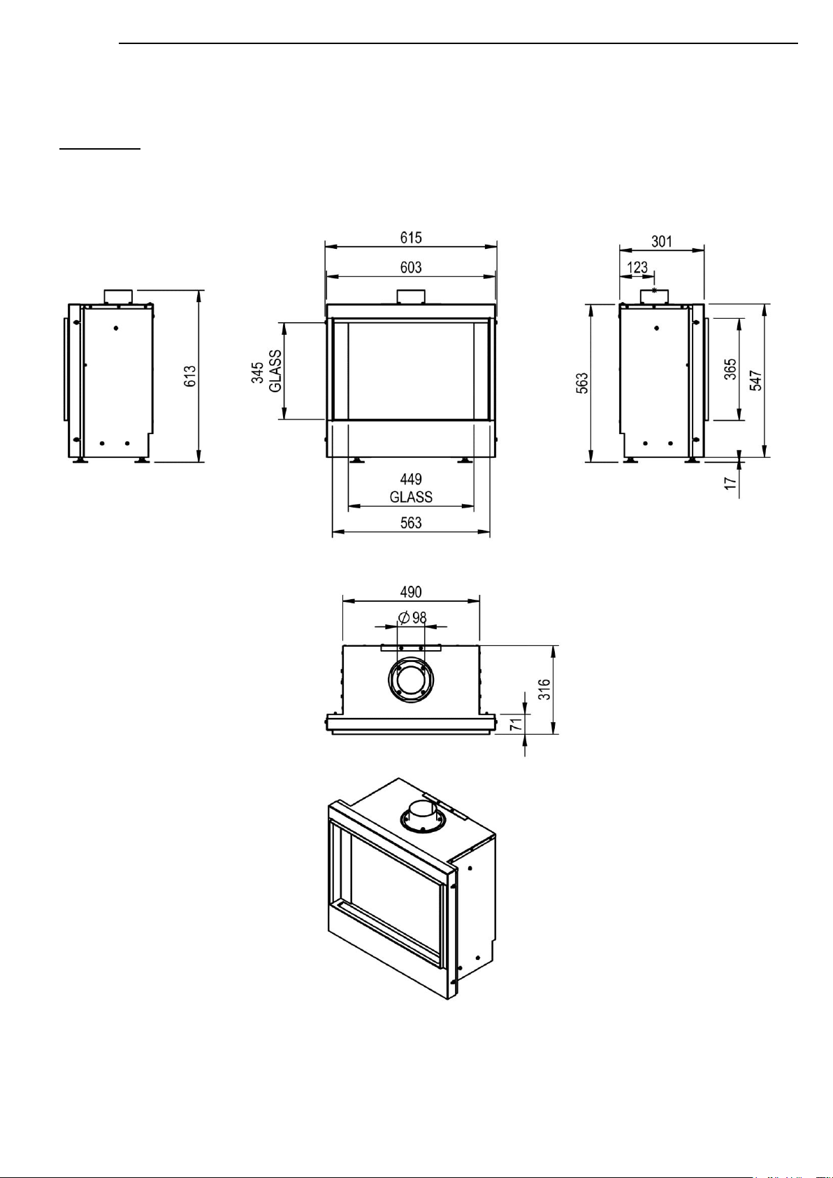
Iconic 500
a. Please Note Flue size 100 mm
b. Please Note the Adjustable Legs could be adjusted from 17 - 50mm
2
Page 3
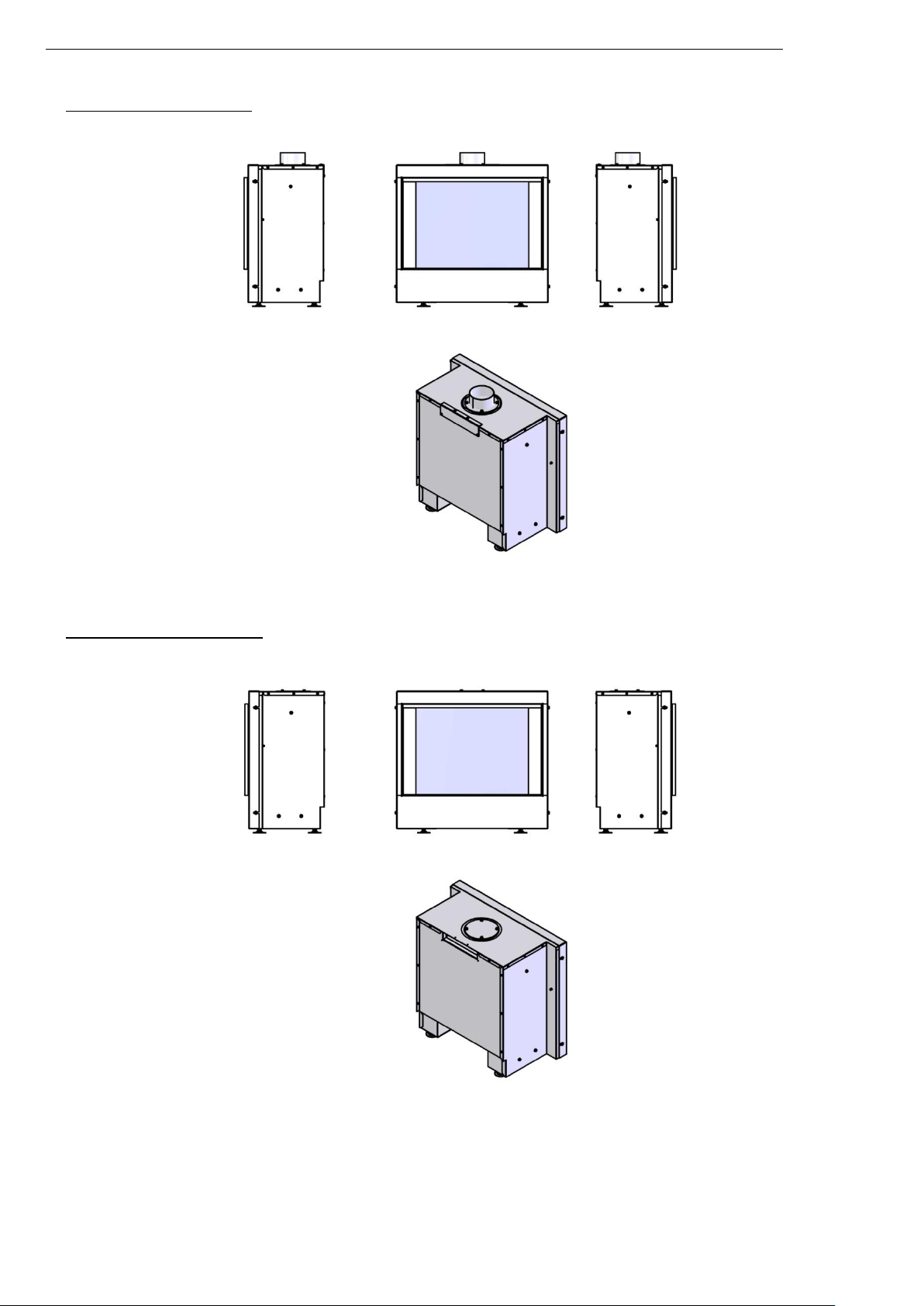
Iconic 500 – Top Flue
IE & GB
Iconic 500 – Rear Flue
3
Page 4
IE & GB
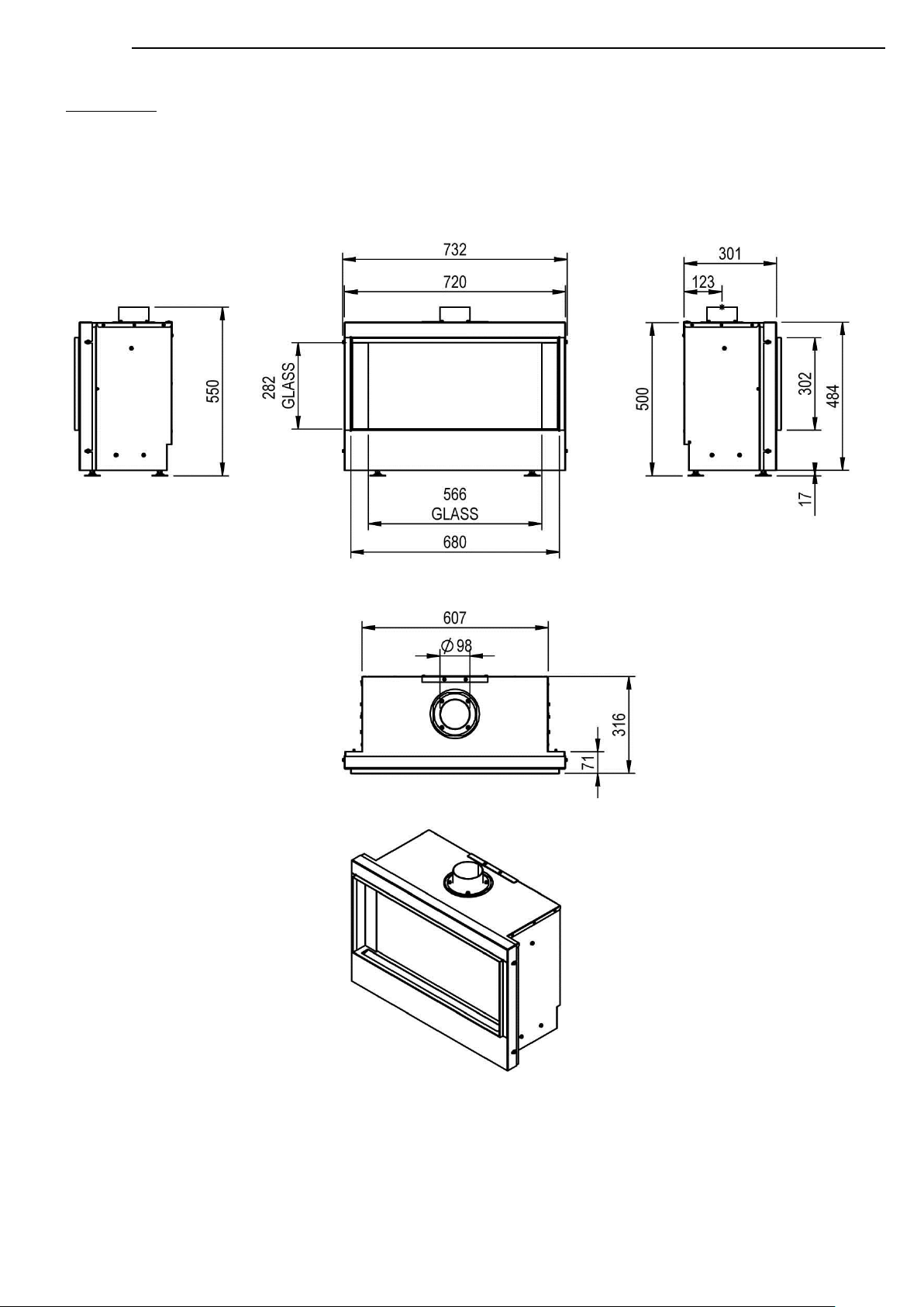
Iconic 600
a. Please Note Flue size 100 mm
b. Please Note the Adjustable Legs could be adjusted from 17 - 50mm
4
Page 5
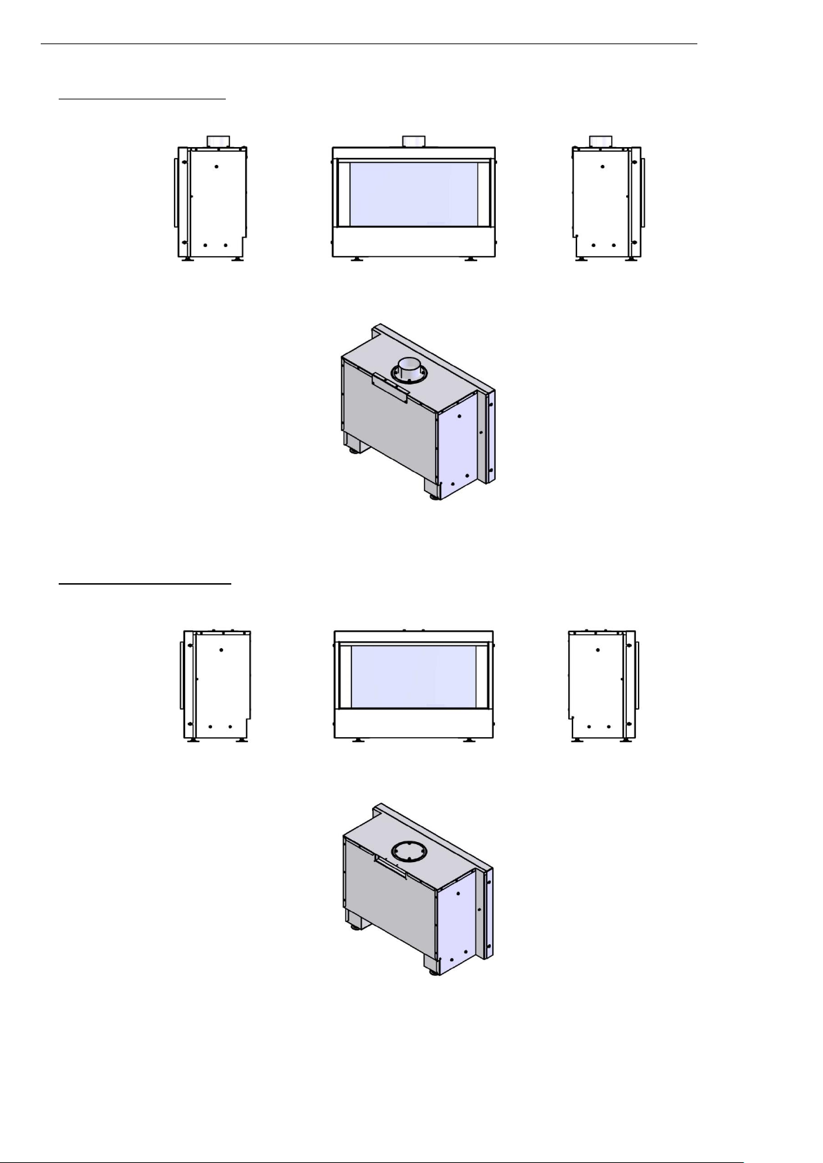
Iconic 600 – Top Flue
IE & GB
Iconic 600 – Rear Flue
5
Page 6

IE & GB
Content
1. General Notes 7
2. User instructions. 8
2.1 First Time of Operation 8
2.2 Remote Control Overview 8
2.3 Batteries 8
2.4 Replacing the batteries 8
2.5 Setting the Transmitter code 9
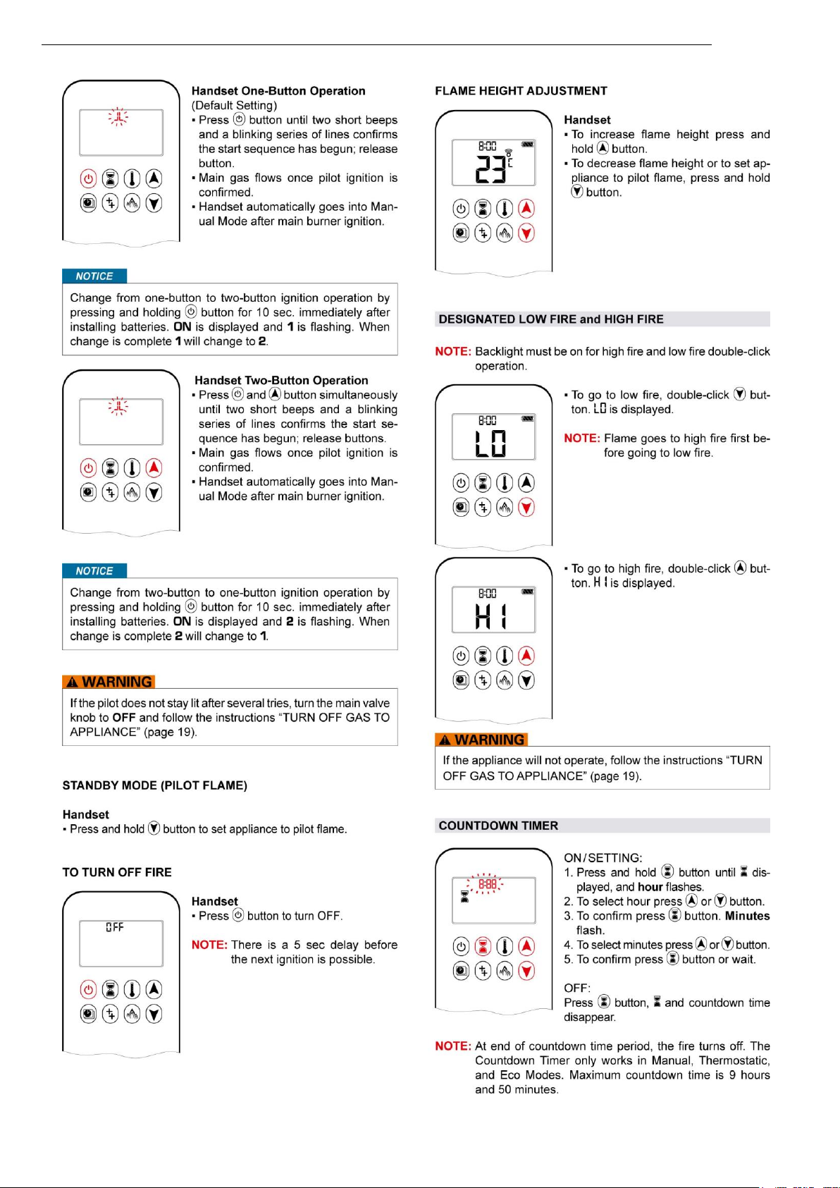
To Ignite the appliance 9
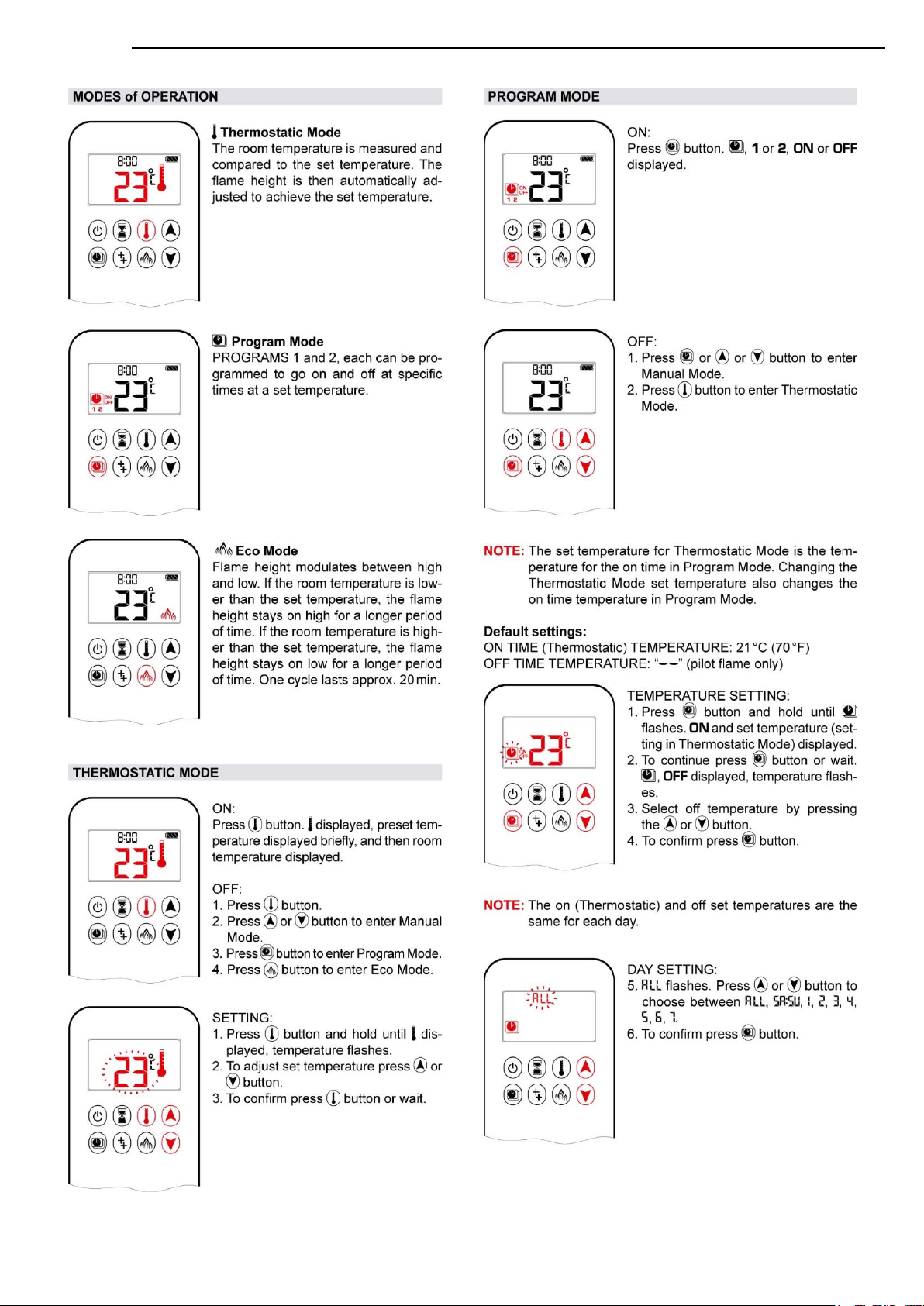
Operating the RC general Notes 9
Setting-Up the RC general Notes 10
Setting °C/24 hour or °F/12 hour clock 10
Setting the Time 10
To Turn OFF the appliance 11
Adjusting the Flame setting 11
2.6 Cleaning and Maintenance 13
3. Installation instructions. 14
3.1 Gas Connection 14
3.2 Ventilation 14
3.3 Appliance Fireplace Installation 14
3.4 Flue Connection 17
3.5 Fuel Bed Arrangements 18
3.6 Commissioning the appliance 23
4. Servicing 24
4.1 Cleaning the Ceramics 24
4.2 Servicing the Burners 24
4.3 Spare parts 25
5. Technical Information 26
5.1 Countries of Use 26
5.2 Technical Data 27
6
Page 7

IE & GB
1. General Notes
This Heat Design gas appliance is a High Efficiency, Live Fuel Effect appliance. It provides radiant and convected
heat using the latest burner technology. As well as having a variable heat output.
Before Installation, check that the local distribution conditions, nature of the gas and pressure, and adjustment
of the appliance are compatible.
This appliance is intended for use on a gas installation with a governed meter.
This Gas Installation may only be installed by a registered professional competent person (A Qualified Gas
Engineer in IE [RGII] and UK [Gas Safe]). The installation must adhere to the requirements of the local and
national Building regulations and national standards. The installation manual must also be followed.
Ensure that the Flue Terminal is not in any way obstructed and is clear of vegetation, i.e. trees, shrubs etc. and
that no objects are leant against the terminal or guard.
Always clean the Window Panel before the fire is ignited. Any finger prints must be removed, as
these will be burnt into the glass and will be un-removable.
Do not operate this appliance if the glass panel has been broken (or cracked), removed or is open.
The appliance is designed to fit numerous installation situations as listed in these installation instructions.
However only flue approved by Heat Design for this appliance may be used.
This appliance is rated at 6.9kW, and as such needs no additional ventilation. However an adequate supply of
fresh air to maintain temperatures and a comfortable environment is recommended. If an extractor fan or any
appliance that could depressurise the room is present a spillage test should be carried out to ensure these do
not affect the operation of the fire, if these appliances do affect the operation of the fire then the fire should
not be installed unless they are permanently disconnected.
This appliance is designed as a heating appliance, and as such will get very hot in operation; all surfaces (except
the controls and access door) are considered to be working surfaces and as such should not be touched. The
front windows and surrounds are not considered to be fully secure guards against accidental contact. It is
recommended that an approved fire screen be used if children, the elderly or persons with limited mobility are
to be present in the same area.
Do not place curtains, laundry, furniture etc. within a safe distance of 300mm of this appliance.
Do not attempt to burn rubbish on this appliance.
If this appliance is extinguished, on purpose or other, no attempt to relight should be made within 3 minutes.
This appliance incorporates an ODS Monitoring system. This is located on the front of the Burner and must not
be adjusted by the installer. This ODS Monitoring system must not be put out of operation, and if any parts
require changing, only original manufacturer parts shall be used.
7
Page 8
IE & GB
2. User instructions.
2.1 First Time of Operation Standard GV60 with Symax RC
Before igniting the appliance, ensure that all packaging, safety stickers and any protective wrapping have been
removed, and that the glass has been cleaned, including all fingerprints from the glass as these will be burnt on
the glass otherwise.
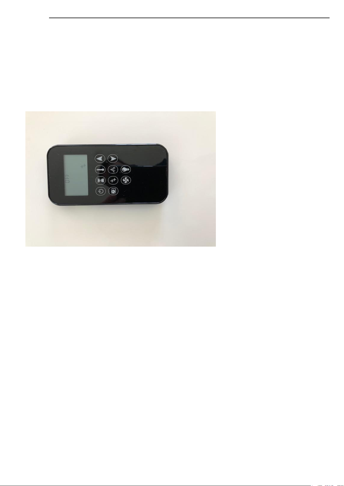
2.2 Typical Look of Symax 10 buttons RC Handset
This RC can be used with WiFi smart phone and tablet app for IOS and Android.
2.3 Batteries
Remote Handset:
2 x 1.5V AAA Batteries, Quality alkaline recommended
Receiver:
4 x 1.5V "AA", Quality alkaline recommended for maximum life.
An alternative AC Mains Adaptor may be used to power the Receiver instead of the 4 AA batteries. Only an AC
Mains Adapter supplied by Heat Design may be used. The Mains Adaptor is plugged into the DC 6V socket on the
end of the receiver.
Note - if the AC Mains Adapter is used, remove the 4 AA's from the Receiver, failure to do so could result in
damage and failure of the Receiver. During a period of power outage, the receiver may be unplugged and
batteries returned to the Receiver.
2.4 Setting the Transmitter code
Press and hold the RESET button with a sharp object (pen or screwdriver) until you hear two audible beeps.
After the second, longer beep, release the RESET button.
Within the next twenty seconds press the down button on the remote handset until you hear an additional long
signal confirming the code is set.
On the ICONIC 500 and 600 models the Receiver is located in the front under the trim panel.
8
Page 9
IE & GB
9
Page 10
IE & GB
10
Page 11
IE & GB
11
Page 12
IE & GB
12
Page 13

IE & GB
2.6 Cleaning and Maintenance
This appliance should be inspected and serviced once a year by a qualified, competent and registered person.
The inspection and maintenance must at least take place once a year to ensure that the appliance is working
correctly and safely. It is advisable to clean the appliance of any dust and debris before and regularly during the
heating season and especially if the appliance has not been used for some time. This can be done with a soft
brush and a vacuum cleaner or a damp cloth and if required a non-abrasive cleaning agent. Do not use corrosive
or abrasive substances to clean the appliance.
13
Page 14

IE & GB
3. Installation instructions.
Before commencing Installation, confirm that the details on the appliance data plate correspond to the local
distribution conditions, gas type and pressure to which the appliance is to be installed.
Ensure that gas supply and supply pipe is capable of delivering the required volume and pressure of gas and is in
accordance with the rules in force.
3.1 Gas Connection
This appliance has a gas inlet connection of Ø 8mm.
3.2Ventilation
This appliance does not need extra air vent. However an adequate supply of fresh air to maintain temperatures
and a comfortable environment is recommended. Ref (IE, current edition of IS 813 Domestic Gas Installations /
GB, BS 5871 part 2)
3.3 Appliance Fireplace Installation
Determine the position required for the appliance.
Create a gas connection for the appliance in approximately the correct location for the gas controls.
The gas controls are connected to the Burner of the appliance. These controls are located under the fire with
easy access from the front, when removing the front trim.
This appliance has fully adjustable legs, these must be set to the desired length before the flue position is
finalised. Fine adjustment of the legs is available via the adjustable feet.
Do not make any adjustments to the appliance, except the leg length.
The appliance should be fitted with a minimum clearance of 100mm from any combustible objects or materials;
this includes any combustible materials used for the fireplace construction.This clearance distance can be
reduced to 50mm if a Cement Board, of minimum thickness 12mm is used. This Cement Board will act as a
Thermal Break.
The clearance distance of the Flue from combustibles must not be less than 75mm. This dimension can be
reduced to 25mm as the distance from the underside and the sides of Horizontal Flue runs.
The appliance should stand on appropriate legs, and a hearth or non combustible floor is required for this
appliance.
A gap of 50mm should be left all around the appliance.
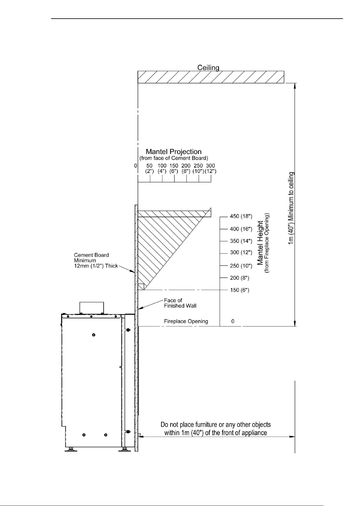
If a shelf is to be fitted above the fireplace opening, a gap of 150mm minimum should be left between the
opening and the shelf. See section 3.3.3, Mantel Clearances.
The brackets supplied may be used for securing the appliance to a rear wall.
3.3.1 Building the Fireplace
Construct a studwork fireplace to the desired sizes, minimum sizes are shown in section 3.3.2. Any combustible
material used to construct the Fireplace must not be closer than the minimum dimensions quoted in section 3.3
above. Cement Board of minimum thickness 12mm, can be used as a Thermal Break and can be used directly
against the Frame Face on the appliance.
Do not use insulation material (or other) to pack the void around or above the appliance.
Provide ventilation from the fireplace to the minimum amount quoted in 3.3 above.
14
Page 15
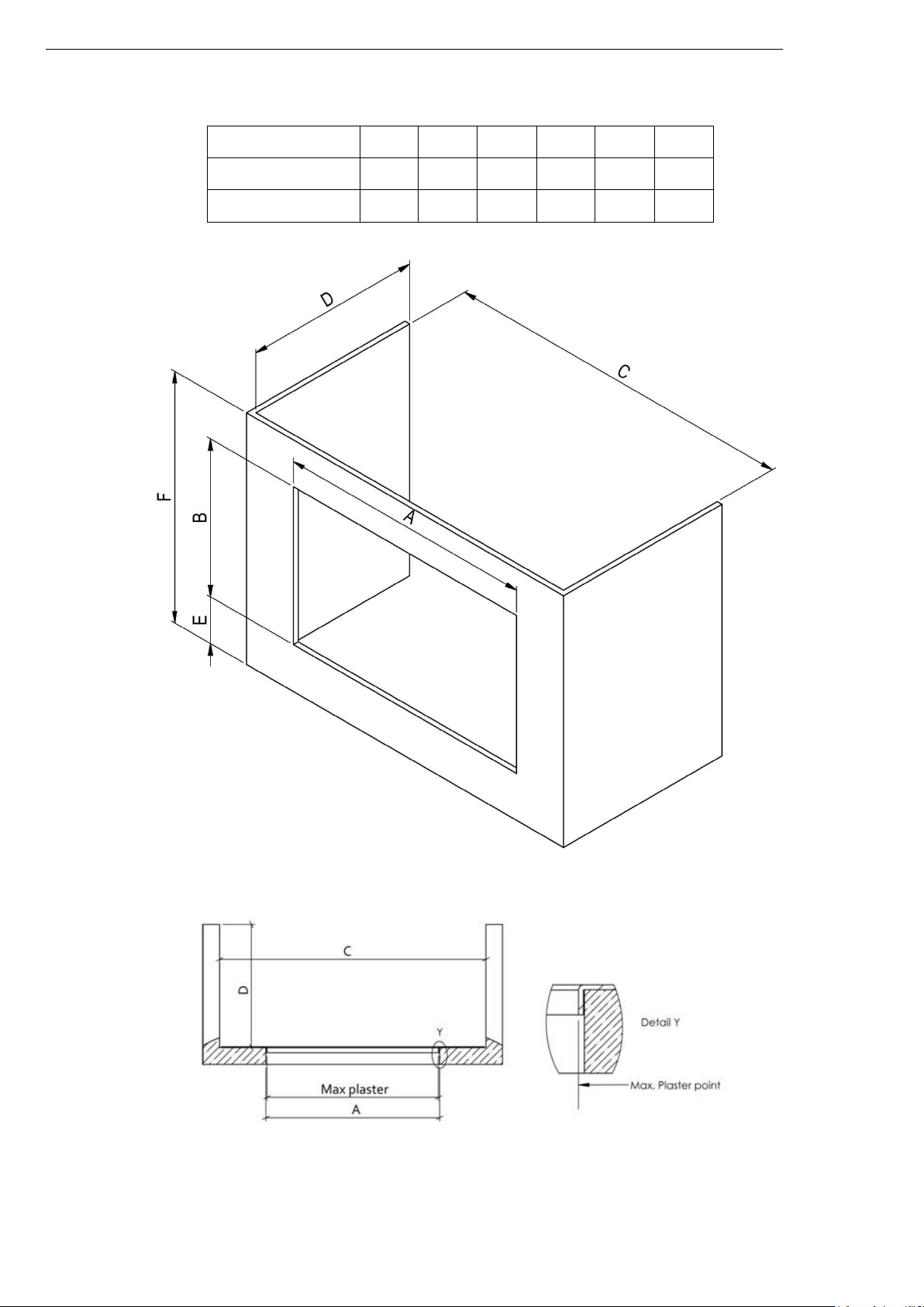
3.3.2 Built-In Fireplace Sizing (assuming a Cement Board Lining is used)
Appliance
A min
B min
C min
D min
E min
F min
Iconic 500
563
365
715
351
149
663
Iconic 600
680
302
832
351
149
600
IE & GB
15
Page 16
IE & GB
3.3.3 Mantel Clearances
3.3.3 Combustible Mantel – Side view
16
Page 17

IE & GB
3.4 Flue Connection
3.4.1 General notes
This appliance may be installed with a roof termination with rigid or flexible pipes, or in a masonary chimney
class 1 or class 2 and without lining the flue. The flue system must be constructed from the appliance upwards,
with all joints being fully locked and sealed using the Heat Design specified parts.
3.4.2 Timber Frame Construction
Whilst it is possible to install room-sealed appliances in timber frame properties, great care needs to be taken
to ensure that the flue assembly does not interfere with the weatherproofing qualities of any outer wall which it
may penetrate. Before attempting this work, it is advisable to consult with a qualified installer.
3.4.3 Carport or Building Extension
Note: A covered passageway should not be treated as a carport. Flues should not be sitedin a covered
passageway between properties.
17
Page 18
IE & GB
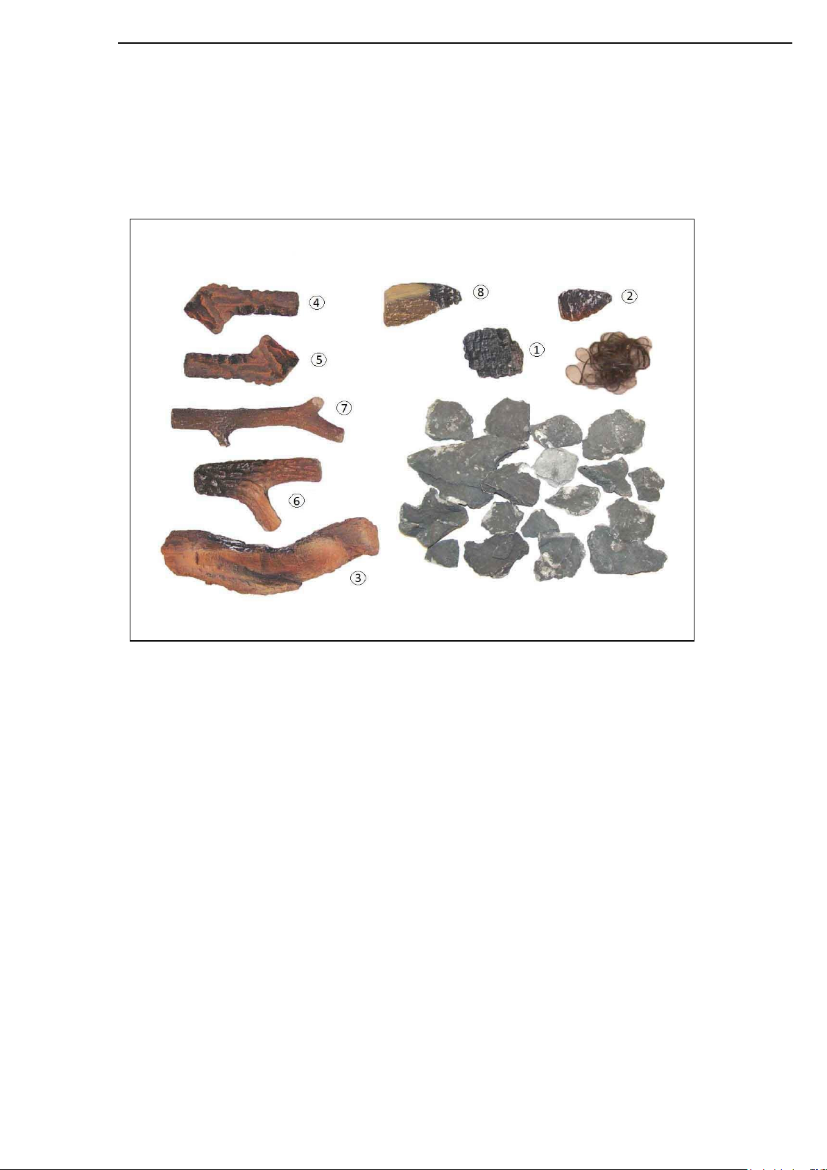
Log set Identification
3.5 Fuel Bed Arrangements.
When arranging the Media (Fuel Effect) into the Firebed, it is imporant that the Pilot area is kept clear and that
no Media enters the Pilot shield. The Pilot area includes the pilot shield and the top of the burner to the first
slot inside the fence of the pilot shield.
When commissioning or servicing the Appliance Cross Lighting must be checked to ensure smooth lighting of the
main burner from the Pilot Flame and smooth lighting of the effect burners from the main Burner.
Shown above is the Log set Used for the Heat Design Iconic 500 and Iconic 600.
This will include: 1 Bag of Grey Embers, 8 Logs and a Bag of Glow Strands.
18
Page 19
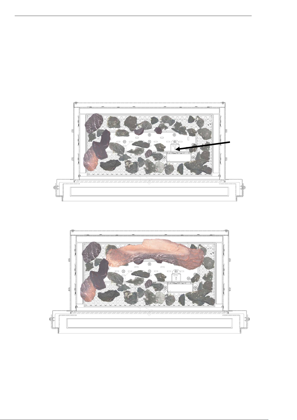
3.5.1 Iconic 500 – Log Layout
Scatter the Embers over the top of the burner as shown, KEEPING THE PILOT AREA CLEAR.
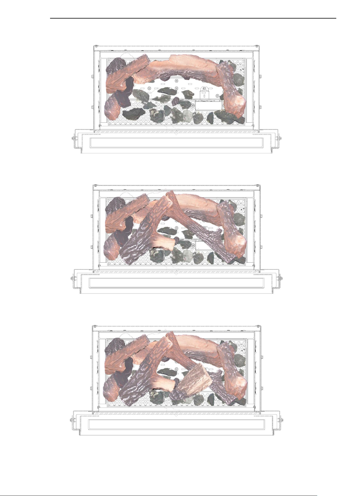
Position the 8 logs as shown.
Lay the glow strands amongst the logs in the flames to create an enhanced Glow.
1 2 3
Pilot and Cross
Light left clear.
IE & GB
19
Page 20
IE & GB
5
6 8 4
7
Position the Log 8, as shown in the diagram.
Finaly Check the appliance for Pilot ignition and cross lighting ensuring that no
material is impinging the opertion of the Pilot.
20
Page 21
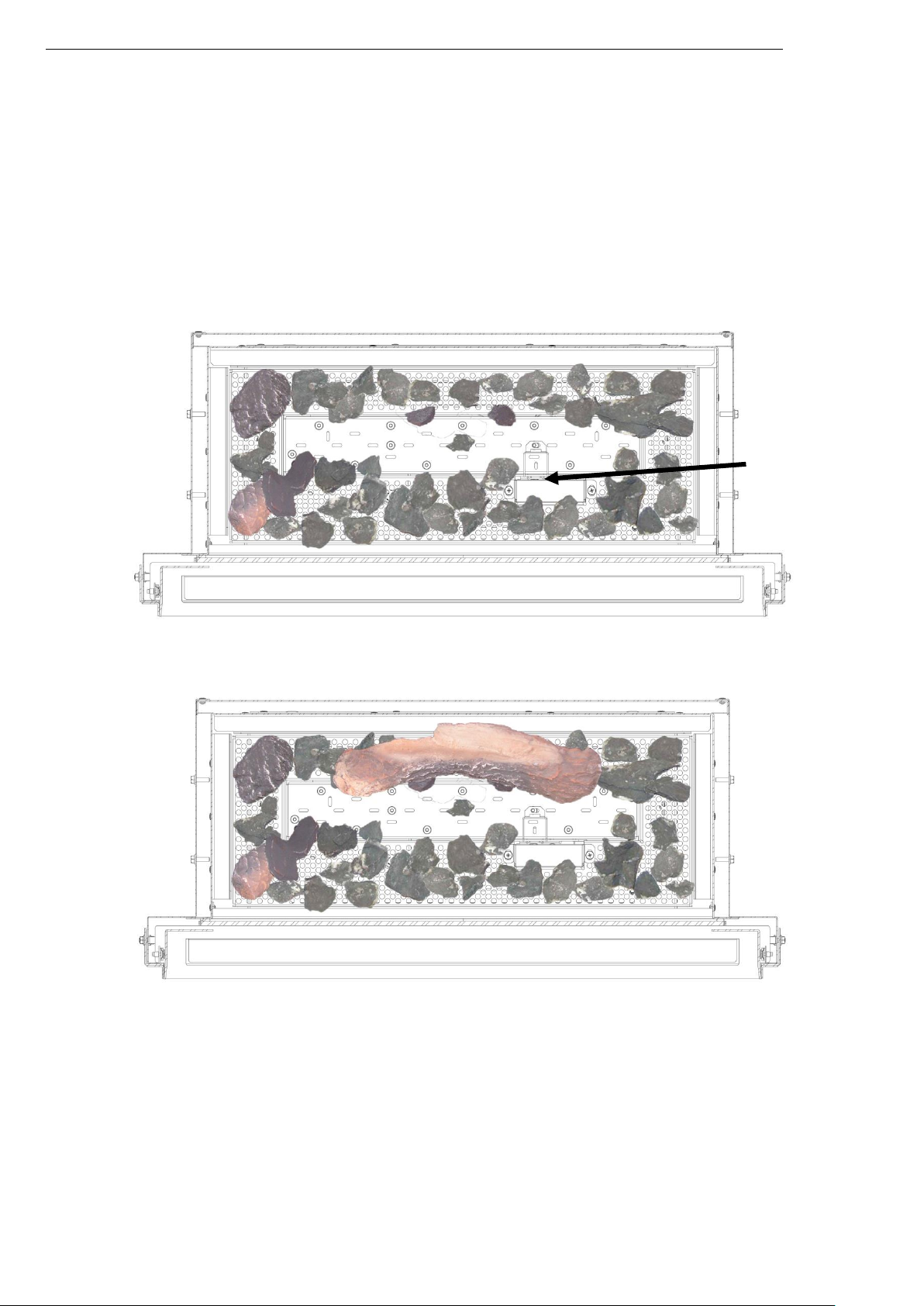
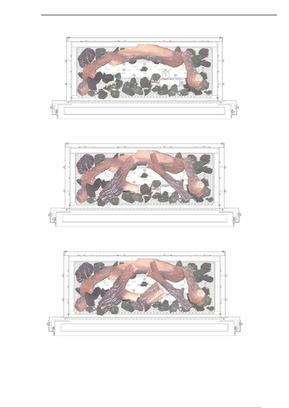
3.5.2 Iconic 600 – Log Layout
2
Scatter the Embers over the top of the burner as shown, KEEPING THE PILOT AREA CLEAR.
Position the 8 logs as shown.
Lay the glow strands (Embers) amongst the logs in the flames to create an enhanced Glow.
3
1
Pilot and Cross
Light left clear.
IE & GB
21
Page 22
IE & GB
4 5 6
7
8
Position the Log 8, as shown in the diagram.
Finaly Check the appliance for Pilot ignition and cross lighting ensuring that no
material is impinging the opertion of the Pilot.
22
Page 23

IE & GB
3.6 Commissioning the Appliance
3.6.1 Pilot Ignition Check
1. Ignite the pilot light as described in the User Instructions
2. Check that the pilot flame stays alight
3. Extinguish the pilot light
3.6.2 Main Burner Check
1. Ignite the pilot light as described in the User Instructions
2. Turn on the main burner as described in the User Instructions
3. Check that the pilot smoothly cross-lights to the main burner and that the main burner and pilot stay alight
4. Extinguish the appliance fully
3.6.3 Pressure Check
The appliance is preset to give the correct heat inputs as listed in the technical details. No further adjustment is
necessary. Always check the inlet pressure and burner pressure.
1. Turn off the gas valve on the appliance
2. Release the screw on the Inlet Pressure test point on the gas valve and connect a pressure guage Manometer
3. Check that the measured pressure is as the prescribed supply pressure
4. Perform the test when the appliance is burning on full and with only the pilot alight
5. If the pressure is low, check the gas supply pipes are to a correct sizing
6. If the pressure is too high (more than 5 mbar over) the appliance may be installed, but the gas supply company
should be contacted
7. Release the screw on the Burner Pressure test point on the gas valve and connect a manometer
8. Check that the measured pressure is as detailed in the Technical details
9. The measured value should be within +/- 10% of the described value. If this is not the case, please contact the
supplier.
Note: After checking the pressures and removing the manometers, the screws in the Pressure Test points must be
closed, and the system must be checked for gas-tightness.
23
Page 24

IE & GB
4. Servicing
Turn the appliance OFF and isolate the gas supply. Ensure the appliance is fully cold before attempting to start
servicing the appliance. No liability can be accepted by Heat Design for injury caused by burning or scolding by a
hot appliance.
A suggested procedure for servicing is listed below.
A. Lay out dust sheet on flooring, mask off any special fireplace materials.
B. Remove Side Window Trims
C. Remove Bottom Window Trim
D. Remove Window Assembly
E. Carefully remove the Ceramic components (including Embers) or Gravels
F. Use a Vacuum cleaner to clean the top of the burners and grate
G. Remove Grate
H. Using a vacuum cleaner, fully clean around the Burner
I. The Pilot Assembly is clearly visible. Use the vacuum cleaner and a soft brush to clean the pilot assembly
Never modify or bend the Thermocouple
J. Turn on the gas supply and check for leaks, check the burners and Pilot for good condition and operation
K. Replace Grate
L. Replace the Firebed arrangements
M. Replace Window Assembly and Trims
N. Check the flue system and terminal, making sure that the terminal vent is fully clear
O. Light the appliance and test setting pressures
P. Check the safe operation of the appliance
4.1 Cleaning the Ceramics
Remove the ceramics as detailed in A - E above.
Gently clean the ceramics in the open air, using a soft brush and a vacuum cleaner. Where necessary replace
damaged components only with genuine Heat Design specified parts. Seal any scrap ceramics in plastic bags and
dispose at proper refuse sites. When using a vacuum cleaner, it is recommended that one with a HEPA filtering
system is used.
Re-fit the Firebed arrangement, re-seal the appliance and check the safe operation of the appliance.
4.2 Servicing the Burners
Remove the Burner Top Assemblies as detailed in A - H above.
The pilot is now clearly visible, the pilot, including the Thermocouple, can be replaced/ serviced by removing
raising the pilot assembly from its mounting. This is done by removing the two screws on the surface of the
pilot. The fittings on the under-side of the pilot can be un-done using a 10mm spanner where appropriate.
To access the Main Burner Injectors, the Burner base units must be removed. This is done by removing the four
bolts (M5, 8mm socket tool) holding the burner in. With these four bolts removed, the Burner base can be raised
up through the Firebox, and the Injectors can be easily accessed.
When replacing any parts use only original Heat Design specified parts.
24
Page 25

IE & GB
4.3 Spare parts
Item Iconic 500 Spare Parts Iconic 600 Spare Parts
Front Window Panel 2B01027 2B01027.6
Ceramic Log Pack 2B01_LOGS
Ember Pack 2B01_EMBR
Pilot Assembly Natural G30-ZP2-312.ODS
Pilot Assembly LPG G30-ZP2-271.ODS
Electrode Lead G60-ZKIS1/.ODS
Injector Natural EG05177.320 EG05177.400
Complete Burner Assembly Natural 2A01105 2A01105.6
Complete Burner Assembly LPG 2A01106 2A01106.6
Grate Assembly 2A01054 2A01054.6
Gas Valve Assembly Natural 2B_N1_GV60 2B_N1_GV60.6
Gas Valve Assembly LPG 2B_P1_GV60 2B_P1_GV60.6
Receiver unit B6R – R8P
Handset B6R – H8TL3PW
25
Page 26

IE & GB
5. Technical Information
5.1 Countries of Use
Country Natural LPG
AT -Austria I2H, G20 at 20 mbar I
,G31 at 50 mbar;I
3P(50)
3B/P(50)
mbar
BE -Belgium I
mbar;I
BG -Bulgaria I2H, G20 at 20 mbar I
CH - Switzerland I2H, G20 at 20 mbar I
mbar;I
, G20/G25 at 20/25 mbar I3+,G31/G31 at 28/37 mbar;I
2E+
3B/P(30)
,G31 at 50 mbar;I3+,G31/G31 at 28/37
3P(50)
,G30/G31 at 30 mbar
3B/P(30)
,G30/G31 at 30 mbar
,G31 at 37 mbar;I
3P(37)
at 50
CY -Cyprus I2H, G20 at 20 mbar I3+,G31/G31 at 28/37 mbar;I
at 30 mbar
CZ -Czech Republic I2H, G20 at 20 mbar I
mbar;I
,G31 at 50 mbar;I3+,G31/G31 at 28/37
3P(50)
,G31 at 37 mbar;I
3P(37)
at 50
DE -Germany I
DK -Denmark I2H, G20 at 20 mbar I
EE -Estonia I2H, G20 at 20 mbar I
, G25 at 20 mbar¹;I2E, G20 at 20 mbar I
2ELL
,G31 at 50 mbar;I
3P(50)
,G30/G31 at 30 mbar
3B/P(30)
,G30/G31 at 30 mbar
3B/P(30)
3B/P(50)
ES -Spain I2H, G20 at 20 mbar I3+,G31/G31 at 28/37 mbar;I
mbar
FI -Finland I2H, G20 at 20 mbar I
,G31 at 30 mbar;I
3P(30)
3B/P(30)
mbar
FR -France I
mbar;I
I
, G20/G25 at 20/25 mbar I3+,G31/G31 at 28/37 mbar;I
2E+
,G30/G31 at 30 mbar;
3B/P(30)
,G30/G31 at 50
3B/P(50)
GB -United Kingdom I2H, G20 at 20 mbar I3+,G31/G31 at 28/37 mbar;I
mbar;I
,G30/G31 at 30 mbar
3B/P(30)
GR -Greece I2H, G20 at 20 mbar I3+,G31/G31 at 28/37 mbar;I
mbar;I
HU -Hungary I
HR -Croatia I2H, G20 at 20 mbar I
,G30/G31 at 30 mbar
3B/P(30)
,G31 at 37 mbar;I
3P(37)
,G30/G31 at 30 mbar
3B/P(30)
3B/P(30)
mbar
IE -Ireland I2H, G20 at 20 mbar I3+,G31/G31 at 28/37 mbar;I
mbar
IS -Iceland
IT -Italy I2H, G20 at 20 mbar I3+,G31/G31 at 28/37 mbar;I
mbar;I
,G30/G31 at 30 mbar
3B/P(30)
LT -Lithuania I2H, G20 at 20 mbar I3+,G31/G31 at 28/37 mbar;I
mbar;I
,G30/G31 at 30 mbar
3B/P(30)
LU -Luxembourg I2E, G20 at 20 mbar
LV -Latvia I2H, G20 at 20 mbar
MT -Malta I
NL -The Netherlands I2L, G25 at 25 mbar I
I
, G25.3 at 25 mbar I
2EK
,G30/G31 at 30 mbar
3B/P(30)
,G31 at 50 mbar;I
3P(50)
,G31 at 37 mbar;I
3P(37)
3P(30)
3B/P(30)
mbar
NO -Norway I2H, G20 at 20 mbar I
PL -Poland I2E, G20 at 20 mbar I
,G30/G31 at 30 mbar
3B/P(30)
,G31 at 37 mbar
3P(37)
PT -Portugal I2H, G20 at 20 mbar I3+,G31/G31 at 28/37 mbar;I
mbar
RO -Romania I2E, G20 at 20 mbar I
,G31 at 30 mbar;I
3P(30)
3B/P(30)
mbar
SE - Sweden I2H, G20 at 20 mbar I
,G30/G31 at 30 mbar
3B/P(30)
SL -Slovenia I2H, G20 at 20 mbar I3+,G31/G31 at 28/37 mbar;I
mbar;I
SK -Slovakia I2H, G20 at 20 mbar I
,G31 at 50 mbar;I3+,G31/G31 at 28/37
3P(50)
mbar;I
at 30 mbar;I
,G30/G31 at 30 mbar
3B/P(30)
,G31 at 37 mbar;I
3P(37)
,G30/G31 at 50
3B/P(50)
TR -Turkey I2H, G20 at 20 mbar I3+,G31/G31 at 28/37 mbar;I
mbar;I
,G30/G31 at 30 mbar
3B/P(30)
26
,G30/G31 at 50
,G31 at 37
3P(37)
,G30/G31
3B/P(50)
,G30/G31
3B/P(30)
,G30/G31
3B/P(50)
,G30/G31 at 50
,G31 at 37
3P(37)
,G30/G31 at 30
,G31 at 37
3P(37)
,G31 at 37
3P(37)
,G31 at 37
3P(37)
,G30/G31 at 30
,G31 at 37
3P(37)
,G31 at 37
3P(37)
,G31 at 37
3P(37)
,G31 at 30 mbar;
,G30/G31 at 30
,G31 at 37
3P(37)
,G30/G31 at 30
,G31 at 37
3P(37)
,G30/G31
3B/P(30)
,G31 at 37
3P(37)
Page 27
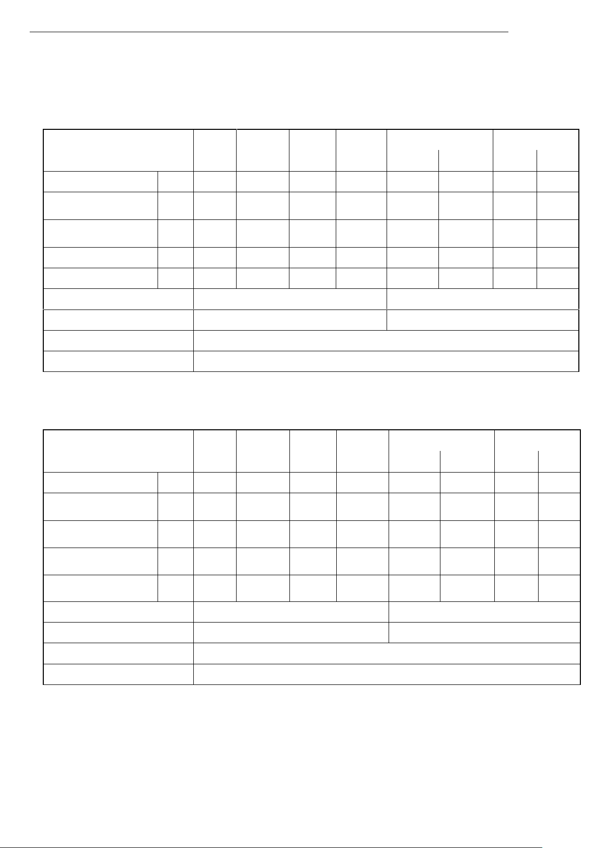
5.2 Technical Data
Gas type
G20
G20/G25
G25
G20/G25
G30/G31
G31
I2H,I2E
I2E+
I2L
I2ELL
I3B/P(30/50)
I3+
I3P(37,50)
I3P(30)
Supply Pressure
mbar
20
20/25
25
20
30/50
28-30/37
37/50
30
Nominal Heat Input
Gross (Hs)
kW
5.1
5.1/5
5
5.1/4.4
4.4
4.4
4.4
4.1
Nominal Heat Input
Nett (Hi)
kW
4.6
4.63/4.54
4.5
4.95/4
4.1
4.1
4.1
3.8
Consumption
m³/hr
0.47
0.47/0.53
0.52
0.47
0.121
0.121
0.157
0.145
Burner Pressure (hot)
mbar
17
17/23
23
17.5
28
28
36
29
Injector Marking
320
120
Pilot
SIT ODS OP9043
SIT ODS OP9288
Efficiency Class
1
Nox Class
5
Gas type
G20
G20/G25
G25
G20/G25
G30/G31
G31
I2H,I2E
I2E+
I2L
I2ELL
I3B/P(30/50)
I3+
I3P(37,50)
I3P(30)
Supply Pressure
mbar
20
20/25
25
20
30/50
28-30/37
37/50
30
Nominal Heat Input
Gross (Hs)
kW
6.3
6.3/5.8
5.8
6.3/5
6.7
6.7
6.7
6
Nominal Heat Input
Nett (Hi)
kW
5.7
5.72/5.27
5.2
5.72/4.54
6.2
6.2
6.2
5.5
Consumption
m³/hr
0.59
0.59/0.65
0.65
0.59/0.6
0.186
0.186
0.24
0.21
Burner Pressure (hot)
mbar
16.5
16.5/23
23
16.5
28
28
35.8
29.2
Injector Marking
400
180
Pilot
SIT ODS OP9043
SIT ODS OP9288
Efficiency Class
1
320
120
Nox Class
5
Product Identification Number: 0359/CS/3203
5.2.1 Iconic 500
IE & GB
5.2.2 Iconic 600
27
Page 28

IE & GB
60 Hawthorn Road, Western Industrial Estate, Dublin 12, D12 E2WF, Ireland.
Tel. : +353 1 4089192
Fax. : +353 1 4089193
Web : www.heatdesign.ie
Email : [email protected]
28
 Loading...