

Heatcraft H-IM-RACC Installation Manual
Installation and Operations
Manual
Bulletin H-IM-RACC August 2007 Part Number 2500018
Replaces H-IM-73A and H-IM-43B
Remote Air-Cooled Condenser
Table of Contents
Inspection ������������������������������������������������������������������������������ 2
Rigging and Moving Units
Installation Requirements
Unit Location
Space and Location Requirements ��������������������������������������� 3
Walls or Obstructions
Units in Pits
Multiple Units
Decorative Fences
Sound Vibration
Vertical and Horizontal Condenser Assembly ��������������������� 4
Typical Piping Arrangements ����������������������������������������������� 5
Installation, Refrigerant Piping
Electrical Wiring ��������������������������������������������������������������������� 6
Start Up ���������������������������������������������������������������������������������� 8
Operation
Winter Operation Head Pressure Control
Fan Cycling Method
Fan Cycling Operation and Installation
Variable Speed
Flooded Head Pressure Control Valve ���������������������������������� 9
Operation
Piping
Maintenance
Cleaning Instructions
System Warranty ������������������������������������������������������������������ 11
In-Warranty Return Materials Procedure
Condenser Specications�����������������������������������������������12-13
General Fan Layout
Dimensions
Replacement Parts by InterLink™ ��������������������������������������� 14
Installation and Operations Manual
Inspection
Shipment should be checked against the bill of lading to verify
that all items listed have been received. All parts should be
carefully inspected to determine if any damage was incurred
in shipment.
Any shortage and/or claims for damage should be immediately
reported to the delivering carrier, followed by ling a claim for
shortages and/or damages.
When uncrating, care should be taken to prevent damage.
Heavy equipment should be left on its shipping base until it
has been moved to the nal location.
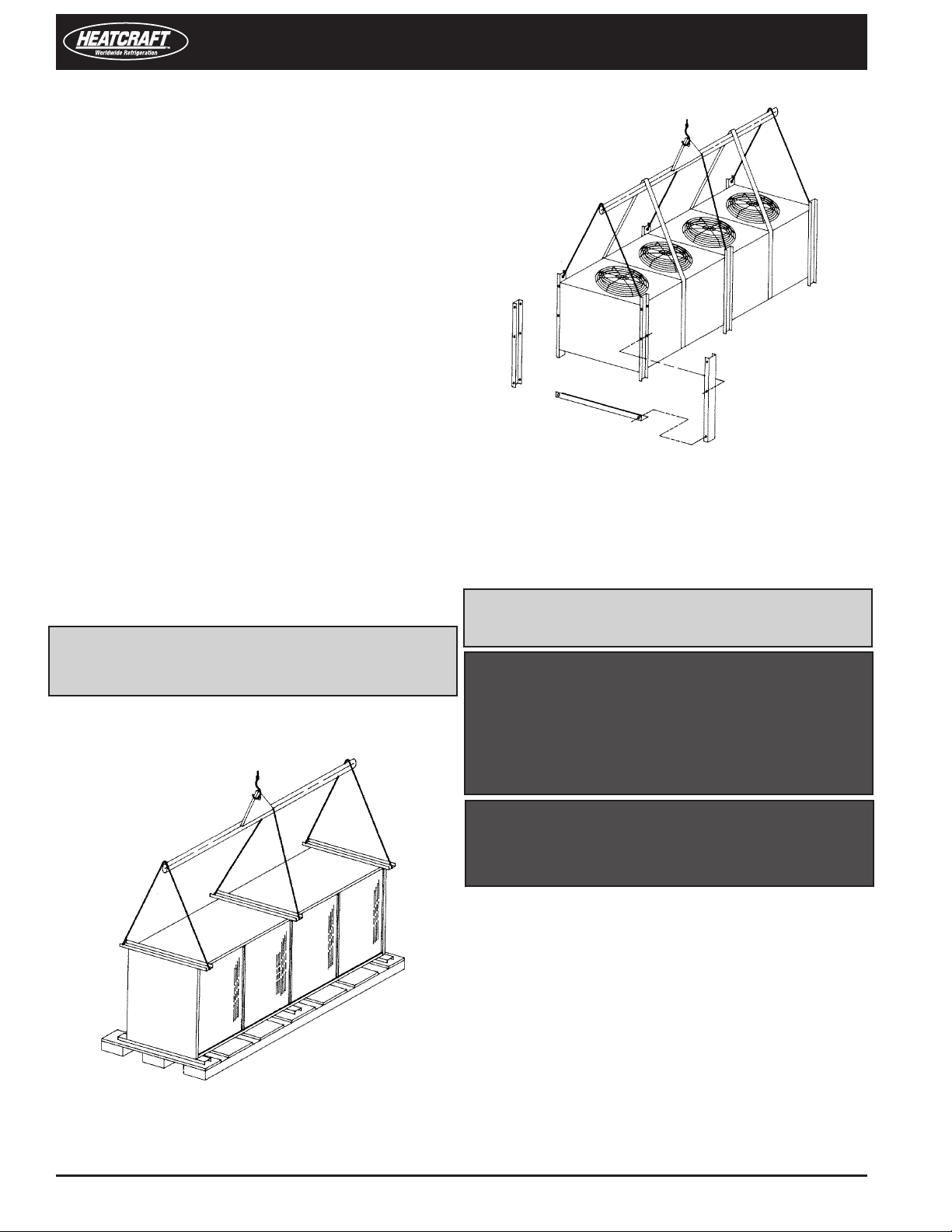
Rigging and Moving Units
The exact method of handling and setting the unit depends
on available equipment, size of unit, nal location and other
variables. It is the judgement of the riggers and movers to
determine the specic method of handling each unit.
All units are shipped on heavy skids and enclosed in open
crating. Generally, it is advisable to bring the unit as close
to its final location as possible before removing crating.
Units are provided with lifting ears near the four corners. Under
no circumstances should the coil headers or return bends be
used for moving these units.
NOTE FOR ALL MODELS: Spreader bars must be used
(contractor-supplied)� Safety slings should be used when
making lift�
Figure 1: Suggested Rigging
Figure 2: Leg Mounting
Installation Requirements
NOTE: Installation and maintenance to be performed only
by qualied personnel who are familiar with local codes
and regulations and are experienced with this type of
equipment�
CAUTION: Sharp edges and coil surfaces are a potential
injury hazard� Avoid contact with them�
WARNING: This equipment may contain a substance that
harms public health and the environment by destroying
ozone in the upper atmosphere� Venting of cer tain
refrigerants to the atmosphere may be illegal in your
location� Refrigerant recovery devices should be used
when installing or servicing this product� Consult your
local codes for requirements in your location�
WARNING: Refrigerant can be harmful if it is inhaled�
Refrigerant must be used and recovered responsibly�
Failure to follow this warning may result in personal injury
or death�
Unit Location
Units are designed for outdoor application and may be
mounted on a roof or concrete slab (ground-level installation).
Concrete slabs used for unit mounting should be installed level
and be properly supported to prevent settling. A one-piece
concrete slab with footings extending below the frost line
is recommended.
Roof-mounted units should be installed level on steel channels
or an I-beam frame to support the unit above the roof. Use of
vibration pads or isolators is recommended. The roof must be
strong enough to support the weight of the unit.
2 Part # 2500018
© 2007 Heatcraft Refrigeration Products LLC
Remote Air-Cooled Condenser
The condenser should be located no closer than four feet from
any wall or other obstruction to provide sucient clearance
for air entrance. Do not attach ductwork to the coil inlet or fan
outlet. Care should be taken to avoid air recirculation conditions
that can be caused by sight screening, walls, etc. Keep unit fan
discharge away from any building air intakes.
Space and Location Requirements
The most important aspect in selecting a location for air-cooled
equipment is a supply of ambient air to the condenser and the
adequate removal of heated air from the condenser area. If
the requirement for adequate air circulation is not adhered to,
higher head pressures will result, creating poor operation and
possible failure of equipment. Units must not be located in the
vicinity of steam, hot air or fume exhausts.
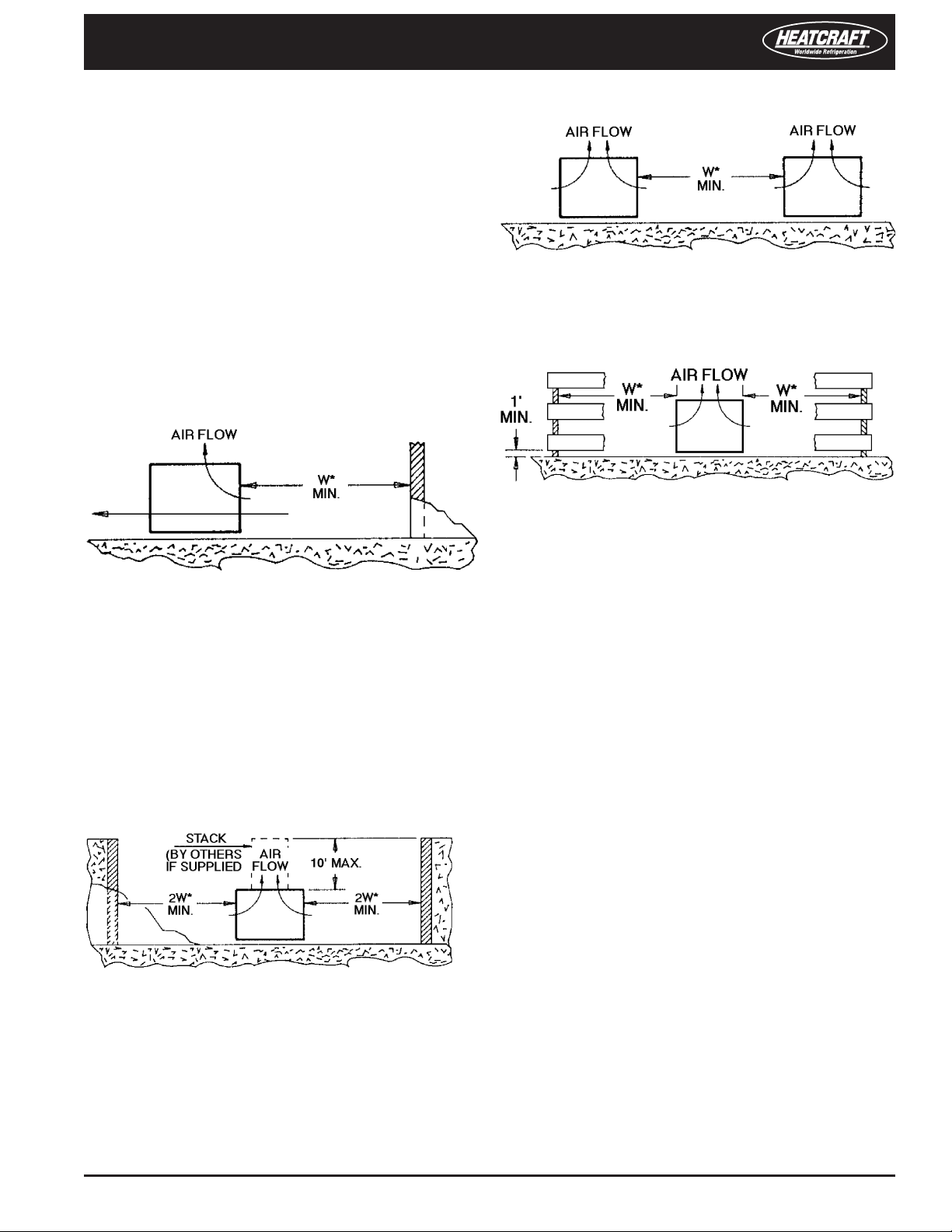
Walls or Obstructions
Multiple Units
For units placed side by side, the minimum distance between
units is the width of the largest unit. If units are placed end to
end, the minimum distance between units is four feet.
Decorative Fences
Fences must have 50 percent free area, with a one-foot undercut,
a minimum clearance equal to the width of the unit and must
not exceed the height of the unit. If these requirements are not
met, unit must be installed as indicated for units in pits.
The unit should be located so that air may circulate freely and
not be recirculated. For proper air ow and access, all sides of
the unit should be a minimum of the width of the unit away
from any wall or obstruction. It is preferable for this distance
be increased whenever possible.
Care should be taken to see that ample room is left for
maintenance through access doors and panels. Overhead
obstructions are not permitted. When the unit is in an area
where it is enclosed by three walls the unit must be installed
as indicated for units in a pit.
Units In Pits
The top of the unit should be level with the top of the pit and
side distance increased to two times the width of the unit.
Sound and Vibration
Units should be installed away from occupied spaces
to redu ce the trans miss ion of soun d and vibratio n
to o ccupied spaces. U nits shou ld be mounted o ver
corridors, utility areas, rest rooms and other auxiliary areas
where high levels of sound are not an important factor.
So und and struc tural consultants should be retained
for recommendations.
Th e refr igerant piping should be flexible enou gh to
prevent the transmission of noise and vibration from the
unit into the building. If the refrigerant lines are to be
suspended from the structure of the building, isolation
hangers should be used to prevent the transmission
of vibration.
Where piping passes through a wall, it is advisable to pack
berglass and sealing compound around the lines to minimize
vibration and retain exibility in the lines. The unit needs to
be secured in its nal location. Holes are provided in the base
runner for this purpose.
If the top of the unit is not level with the top of pit, discharge
cones or stacks must be used to raise discharge air to the top
of the pit. This is a minimum requirement.
*W = Total width of the condenser.
Remote Air-Cooled Condenser Installation and Operations Manual, August 2007 3
Vertical Condenser
Vertical airow units should be located no closer than the width
of the unit from a wall or other obstruction. If two or more units
are to be positioned in the same area, a similar distance should
be maintained between adjacent units. Sufficient free area
should be left around and below unit to avoid air restriction
to coil.
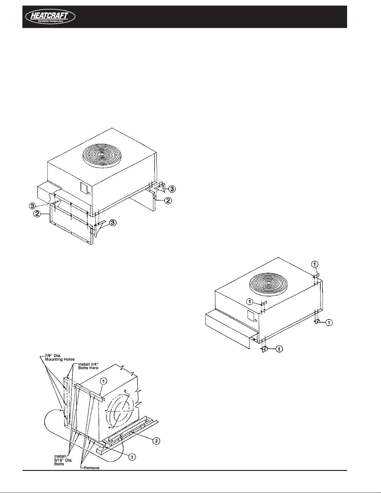
Leg Assembly for Vertical Airow Installation
(Models 008-016; 1-3)
Figure 3. Leg assembly (vertical airow, models 008-016; 1-3)
Installation and Operations Manual
Remove fasteners securing condenser to skid.
1.
Remove leg extensions (Figure 4, item 1) by removing four
2.
5/16” x 3-1/2” bolts.
Install as shown in dotted lines with same four bolts.
3.
Install mounting angle (item 2) as shown (dotted lines) with
4.
four 1/4 - 20 x 3/4” bolts provided.
Condenser can be hoisted by attaching hooks into 1-1/2”
5.
holes in leg assemblies.
Horizontal Condenser
Horizontal airow units should be installed with the coil (inlet
air side) facing the prevailing winds. Where strong winds
are common, it is recommended that a wind deflector (not
supplied) be used to discharge the air vertically from the unit,
to prevent capacity loss during varying wind conditions. The
wind deector should be installed on the fan side of the unit.
If horizontal airow units are installed with the air inlet facing
a wall, a distance of at least 48 inches should be maintained
between unit and wall. If it is necessary to have the unit
positioned so the air discharge is toward a wall, it should be
spaced at a distance no less than three times the coil face
height from the wall.
Assemble the unit’s two legs (Figure 3, item 2) using three
1.
1/4 - 20 x 3/4” long bolts per leg. Captive nuts are provided
on unit for this assembly.
Fo ur gus sets (Fi gure 3 , item 3) are p rovided for
2.
leg support.
Assemble the gusset in each corner with 1/4 - 20 x 3/4” long
3.
bolts and 1/4” nuts.
Discard the four mounting angles (Figure 5, item 1).
4.
Leg Assembly for Vertical Airow Installation
(Models 024-133; 5-26)
Figure 4. Leg assembly (vertical airow, models 024-133; 5-26)
Leg Assembly for Horizontal Airow Installation
(Models 008-016; 1-3)
Figure 5. Leg assembly (horizontal airow, models 008-016 ; 1-3)
Attach four mounting angles (Figure 5, item 1) to the
1.
unit, using two 1/4 - 20 x 3/4” long bolts and 1/4” nuts per
mounting angle.
Discard the two legs, (Figure 3, item 2) and four gussets
2.
(Figure 3, item 3).
4 Part # 2500018
Remote Air-Cooled Condenser
Leg Assembly for Horizontal Airow Installation
(Models 024-133; 5-26)
Figure 6. Leg assembly (horizontal airow, models 024-133; 5-26)
Remove bolts securing condenser to skid.
1.
Remove item 1 and attach to rear of bottom leg (item A)
2.
to complete mounting base. Item 2 is not required in the
horizontal discharge application and may be discarded.
Co ndenser can be hoisted by the 1- 1/2” holes in
3.
leg assemblies.
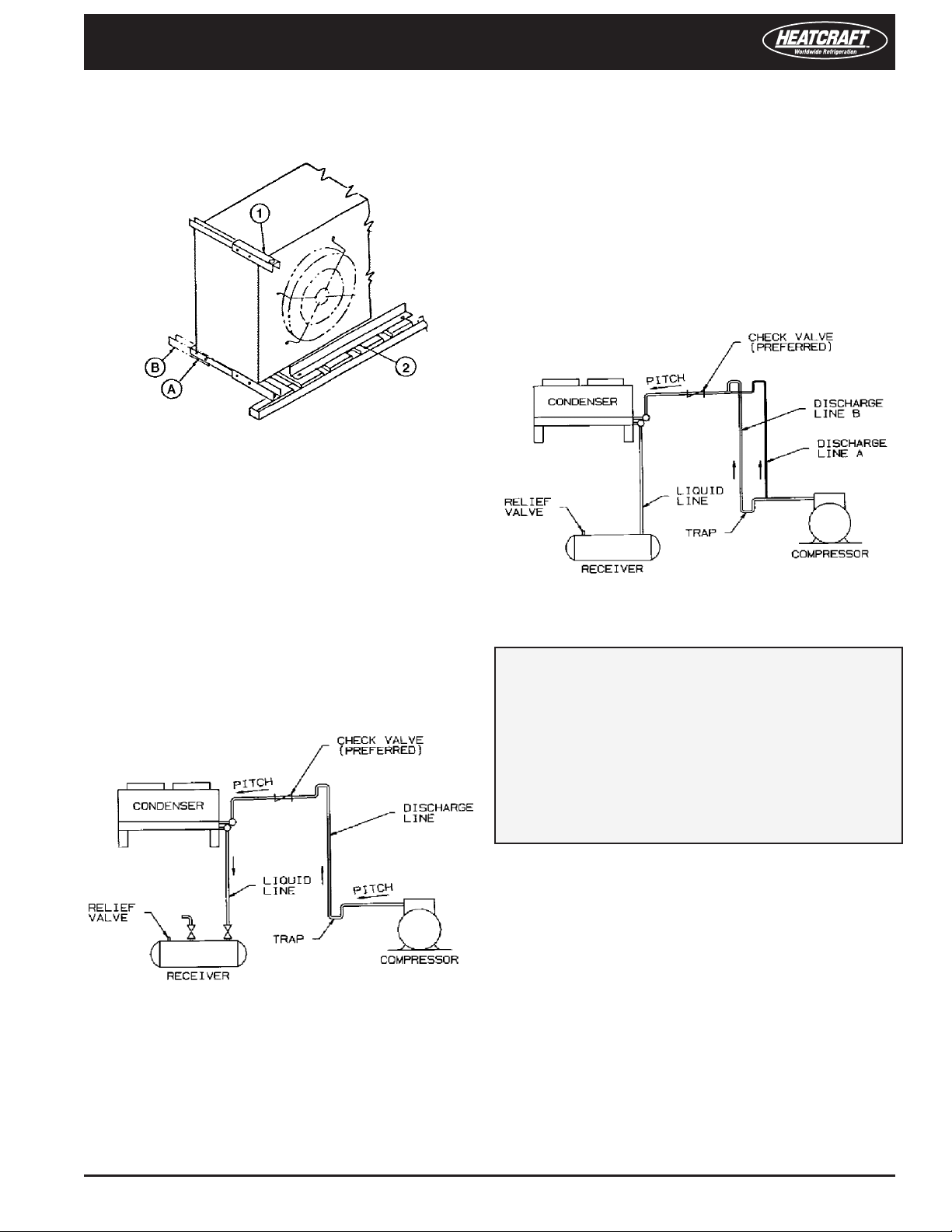
This condition can be overcome in one of two following
ways:
The discharge line may be properly sized for the desired
1.
pressure drop at full load conditions and an oil separator
installed at the bottom of the trap in the discharge line from
the compressor.
A double riser discharge line may be used as shown
2.
in Figure 8. Line A should be sized to carry the oil
at mini mum load con dition s a nd L ine B s hould
be sized so that at full load conditions, both lines would have
sucient ow velocity to carry the oil to the condenser.
Figure 8
Typical Piping Arrangements
Figure 7 illustrates a typical piping arrangement with
a remote condenser located at a higher elevation, common
when the condenser is on a roof and the compressor and
receiver are on grade level or in a basement equipment
room.
Figure 7
In this case, the design of the discharge line is very critical. If
properly sized for full load conditions, the gas velocity might
be too low at reduced loads to carry oil through the discharge
line and condenser coil. Reducing the discharge line size would
increase the gas velocity suciently at reduced load conditions;
however, when operating at full load, the line would be greatly
undersized and create an excessive refrigerant pressure drop.
For more complete information, please refer to the ASHRAE
Handbook on Systems.
NOTES:
All oil traps are to be as short in radius as possible�
1�
Common practice is to fabricate the trap using three
90-degree ells�
Pressure relief valves are recommended at the condenser
2�
to protect the coil�
A drain line check valve is recommended for applications
3�
where the condenser may be at a lower temperature
than the receiver�
See Tables 1, 2, and 3 for discharge and liquid drain line size
recommendations for remote condenser selections.
Installation, Refrigerant Piping
Install piping according to standard accepted refrigeration
practice. The following recommendations should be adhered
to:
Use only refrigeration-grade copper tubing.
1.
Soft solder joints are not acceptable.
2.
Put dry nitrogen through lines while brazing.
3.
Do not leave dehydrated piping or components open to the
4.
atmosphere any longer than is necessary.
Remote Air-Cooled Condenser Installation and Operations Manual, August 2007 5
 Loading...