

Heatcraft H-IM-QRC Installation And Operation Manual

Quick Response
Controller
H-IM-QRC April 2018 Part No. 29702401
Replaces H-IM-QRC (08/17)
Installation and
Operation Manual
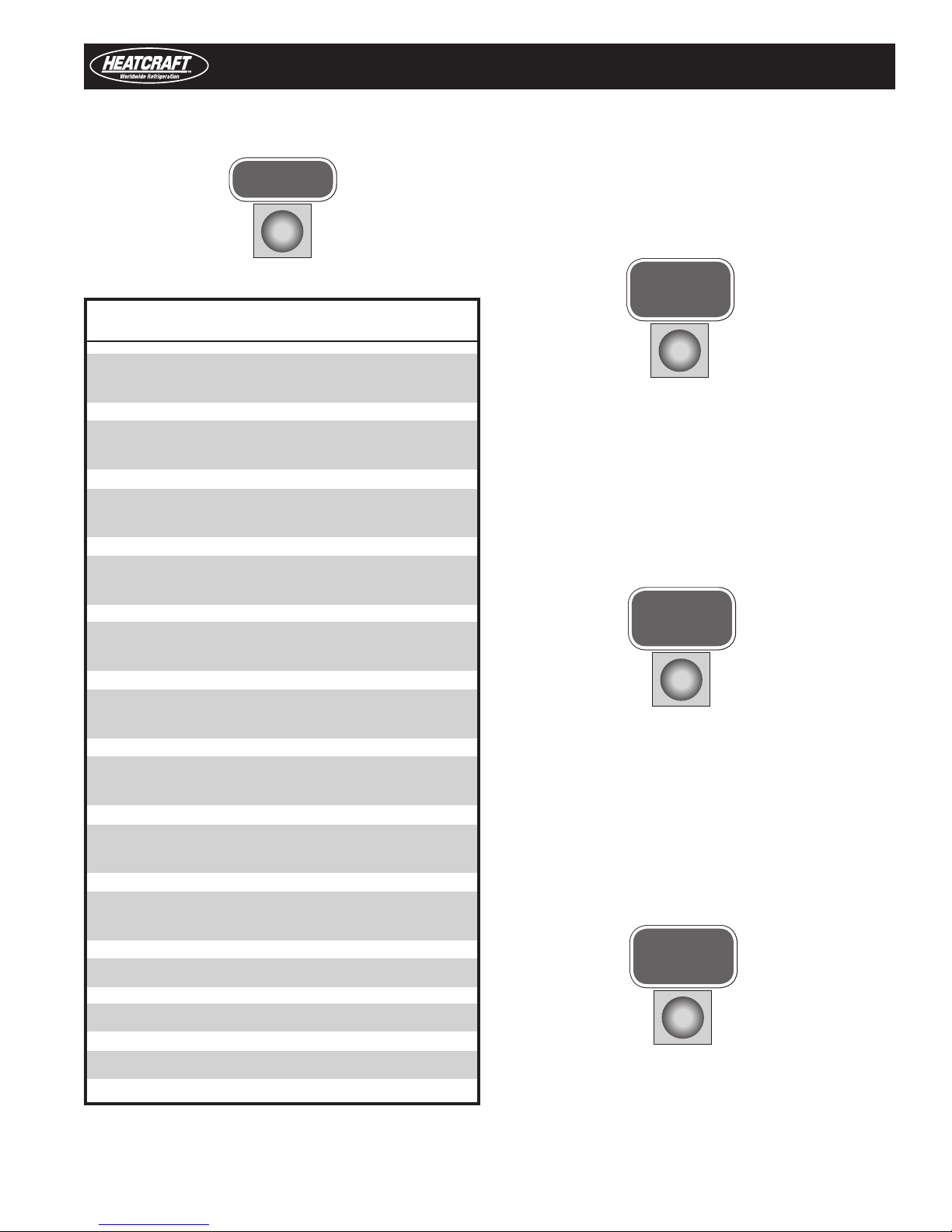
Table of Contents
Heatcraft Quick Response Controller Board Layout ..................................... 2
Installation Tips .......................................................................................... 3
Refrigerant Line Brazing ............................................................................ 4
Power Supply............................................................................................. 4
Wiring ........................................................................................................ 4
Multiple Evaporator Configuration .............................................................. 5
Box Temperature Control Settings .............................................................. 6
Leak Testing .............................................................................................. 6
Start-Up Operation .................................................................................. 7-8
Operating Mode Display ............................................................................. 8
Programming and Reviewing Settings and Changes .............................9-12
Program Review Button
Select Button
Enter Button
Monitoring Items .................................................................................11-12
Monitor Button
Force Defrost Button
Reset Time Button
Force Service Button
Clear/Test Button
Locking The Heatcraft Quick Response Controller Board .......................... 12
Status Indicator LED ................................................................................ 13
Pumpdown .............................................................................................. 13
Defrost ...............................................................................................14-15
Alarms .................................................................................................... 15
Error Indicator .......................................................................................... 16
Checking Operation of Expansion Valve ...............................................17-18
Power Failures ......................................................................................... 18
Spare Sensor Terminals ........................................................................... 18
Checking Sensors .................................................................................... 18
Smart Controller .................................................................................19-20
Sensor Resistance/Temperature Table ...................................................... 21
System Defaults ...................................................................................... 21
Back Compatibility ................................................................................... 22
InterLink Replacement Parts List .............................................................. 23
Operational Limits .................................................................................... 23
Expansion Valve Capacity ......................................................................... 24
Diagnostics ......................................................................................... 24-26
Wiring Diagrams ................................................................................. 27-32
Preventive Maintenance ........................................................................... 33
Service Record ................................................................................... 34-35

Heatcraft Quick Response Controller Board Layout
Heatcraft Quick Response Controller Board
Evaporator
Fan
Relay
EXV
Test Pins
LED
Display
Spare
Temperature
Defrost
Heater
Relay
Alarm
Contacts
Expansion
Valve
Connection
Selection
Buttons
Room
Temperature
Defrost
Temperature
Suction
Temperature
Suction
Pressure
Terminal
Block
©2018 Heatcraft Worldwide Refrigeration
2
Installation
Installation Tips
• Use a minimum 18 gauge wire for all low
voltage connections.
• The Heatcraft Quick Response Controller board
gets its 24 VAC power supply from a transformer
mounted in the electrical end of each evaporator.
On 208-240 volt systems, the multi-tap transformer
is shipped from our factory wired for 240 volts. If
your supply voltage is 208 volt, you must change to
the 208 volt tap on the transformer.
NOTE: On multiple evaporators, since a
transformer is in each evaporator, the
voltage tap must be set on each evaporator.
• Refer to wiring schematic shipped on units for unit
wiring. Schematics in this Installation & Operation
Manual are typical wiring schematics only.
• Program ALL slave evaporators as SLAVES.
• Evaporators are shipped from our factory with a
preset box setpoint temperature of 35°F for air
defrost and -10°F for electric defrost. If your box
setpoint temperature requirements are different,
this must be set using directions outlined under
“Room Temperature Control”.
• Some systems may require the crankcase heater
be energized 24 hours prior to start-up. The
Heatcraft Quick Response Controller should be
de-energized for this period by placing it in the
SERVICE MODE. This is done by pressing the FORCE
SERVICE button twice. To start the system cooling,
press the CLEAR button.
• Room sensors may be left connected on ALL
evaporators. Room sensor must be connected on
the Master Coil.
• A pressure transducer is installed on the evaporator. Do not
leak test system above 150 PSI or damage to transducer
could occur. If leak testing must be greater than 150 psig,
disconnect the transducer from the suction header and
reconnect after testing is complete.
Condensing Unit
Condensing units do not require a Defrost Timer and should
be disconnected if installed. A head pressure control is highly
recommended to be installed in condensing unit.
Condensing unit must be installed using proper refrigeration
practices and codes. Make sure there is sufficient clearances around
unit for adequate air flow and access.
• The suction line temperature sensor MUST be
removed from the suction line before brazing the
suction tubing. The sensor MUST then be reinstalled
on the suction line after brazing is completed and
the tubing has cooled. Insulate when finished.
• If electrical power will be connected prior to
evacuation and charging of system, unplug electric
expansion valve from board until system is ready to
be evacuated, leak tested and charged.
• There are built-in ground connections on the
Heatcraft Quick Response Controller’s four corner
brass spacers. Use four sheet-metal screws to
mount the board on the evaporator for commonmode noise filtering. Make sure that the evaporator
ground terminal is earth grounded.
Typical condensing unit wiring is shown on page 31. The wiring
diagram on page 32 shows how to convert a conventional
condensing unit to use Heatcraft Quick Response Controller with the
system.
Evaporator Unit
The evaporator contains the Heatcraft Quick Response Controller
board, electric expansion valve, pressure transducer, distributor,
orifice, transformer and three sensors. These components are all
factory mounted and wired. The three sensors are factory mounted
and provide input to the controller from the following: defrost
temperature, suction temperature, room temperature
Each evaporator unit must be installed using proper refrigeration
practices and codes. Make sure the piping is correctly sized and
properly routed. It is highly recommended that the liquid and suction
lines be insulated. There must also be good clearance around unit.
See H-IM-UC Installation and Operation manual for more details.
(Available on website).
3
Installation
Refrigerant Line Brazing (Caution)
The electric expansion valve and the suction temperature sensor
on the suction line are factory installed.Care must be taken when
brazing these lines at the evaporator.
Too high a temperature may destroy these components. Heat
absorbing compounds or “wet rags” must be used to protect
the electric expansion valve when brazing the refrigerant line
connections. THE SUCTION LINE SENSOR SHOULD BE REMOVED
BEFORE BRAZING.
Power Supply
The Heatcraft Quick Response Controller board gets its 24 VAC
power supply from a transformer mounted in the electrical end of
each evaporator. On 208-240 volt systems, the multi-tap transformer
is shipped from our factory wired for 240 volts. If your supply voltage
is 208 volt, you must change to the 208 volt tap on the transformer.
VERY IMPORTANT: If the supply voltage to the evaporator is 208
volts, the primary tap of the transformer must be moved to the 208
volt tap.
This must be done for all the evaporators on that system.
If the 24 VAC power supply falls below 18 VAC, the system may
power down and shut off. When the power supply is corrected to 24
VAC, the system will restart after the four minute hold-off period and
resume normal operation.
Wiring
Wiring at the unit cooler(s) will be as follows (see wiring diagrams):
• High voltage - There may be high voltage on
the defrost heater relay and the fan relay.
The evaporator is connected to a separate
power supply from the condensing unit.
See unit cooler spec. plate for ampacity.
• Low voltage wiring must be 18 gauge
minimum. For low voltage wiring, maximum
distances are:
Between evaporators 500 ft.
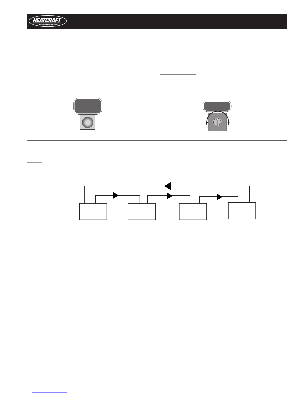
• Multiple units – The multi-in and multi-out
are the communication connections.
Connection sequence must follow the multi out terminal to the multi-in terminal and
the multi-out back to the multi-in terminal in
a daisy chain loop.
• Alarm circuit - The onboard alarm is a dry set of NC
contacts which closes to indicate an alarm or loss of
power. The type and wiring for the alarm is customer
specified. Note that the alarm circuit does not distinguish
or indicate what has caused the alarm.These contacts can
handle up to a 2 Amp load.
On Heatcraft Quick Response Controller systems,the main power
for the evaporator is supplied separately from the power supply of
the condensing unit. All wiring, however, must comply with local
electrical codes.
• All wiring must comply with all applicable codes and
ordinances.
CAUTION: All 24v wiring must be run separate from the line
voltage wiring. Wires/Leads must not touch other component
connection points or power wires to avoid damage to the
board or its components.
4
Configuration
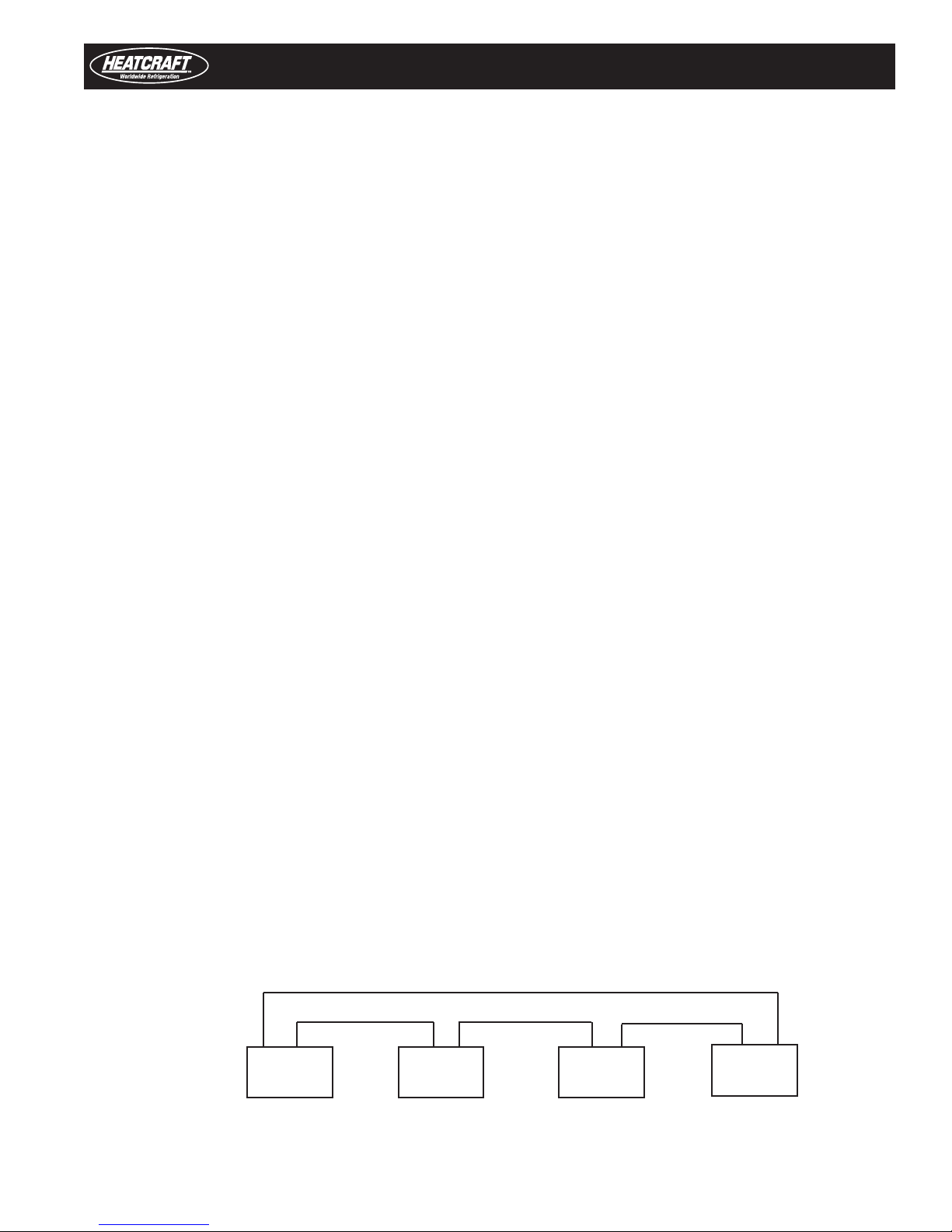
Multiple Evaporator Configuration (Master/slave)
If there are multiple evaporators on a system, the program for
each SLAVE evaporator must be changed to identify it as a SLAVE.
To do so, press the “PROGRAM REVIEW” button repeatedly until
“SLA” appears then use the “SELECT” knob to select “YES” and
press “ENTER”. All Heatcraft Quick Response Controller boards are
shipped with the factory default as a MASTER evaporator. Place all
PROGRAM
REVIEW
Up to 4 evaporators can be connected as a master/slave
configuration.
DO NOT remove the room sensor from any of the Heatcraft
Quick Response Controller boards programmed as Master.
boards in the “SERVICE” mode while you program the setpoints to
avoid errors and alarms which may cause troubles at startup.
VERY IMPORTANT: This must be done for each slave board, prior
to starting the system.
SELECT
M
S
S
S
M = Master Evaporator S = Slave Evaporator
Each Heatcraft Quick Response Controller board power is supplied by a transformer in the evaporator on which
it is mounted. Do not run any 24 VAC wires between Heatcraft Quick Response Controller boards on the evaporators.
5
Box Temp Control Settings
Box Temperature Control Settings
• There is an on board room thermostat on the Heatcraft
Quick Response Controller board which can be adjusted
to the desired room temperature. The temperature
differential is 2°F.
Temperature Differential
When a system is in the cooling mode and the box
setpoint is 35°F, the system will continue to cool until
the box temperature gets to 34°F. At this point, the
compressor will pumpdown and shut off. The system
will restart cooling when the box temperature has risen
to 36°F.
It is important to note that Heatcraft Quick Response
Controller has a minimum 2 minute “ON” time and a
minimum 4 minute “OFF” time. This means that the
system will run in the cooling mode a minimum of 2
minutes even if the setpoint temperature is met. In
applications where the system is grossly oversized,
the box temperature could go below the differential
temperature before the system cycles off.
In the “OFF” cycle the system will be off for a minimum
of 4 minutes even if the box temperature goes above the
differential temperature, before cooling will be restarted.
Leak Testing
After all lines are connected, the entire system must be leak
tested. The complete system should be pressurized to not more
than 150 psig with refrigerant and dry nitrogen. The use of an
electronic type leak detector is highly recommended because
of its greater sensitivity to small leaks. As a further check, it is
recommended that this pressure be held for a minimum of 12
hours and then rechecked. For a satisfactory installation, the
system must be leak tight.
• The on board room thermostat is factory set at 35°F
for Air Defrost systems and -10°F for electric defrost
system.
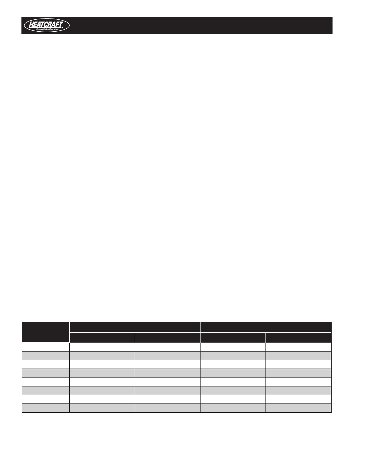
Recommended Low Pressure Control Settings for Outdoor Air Cooled Condensing Units
*Minimum Temp.
˚F
50 90 35 70 40
40 70 35 55 25
30 55 35 40 20
10 45 25 30 10
0 25 7 15 0
-10 20 2 15 0
-20 12 1 10 0
-30 8 0 6 0
* Minimum ambient or box temperature anticipated
* The standard preset low pressure switch used for pumpdown is set for 15 PSI cut in / 4 PSI cut out and is a good setting for most pumpdown systems
R-404A/R-407A/R-448A R-407C
Cut-In PSI Cut-Out PSI Cut-In PSI Cut-Out PSI
6
Start-Up Operation
Start-Up Operation
Single System With 1 Evaporator
• Check all wiring connections to be sure they are
correct and tight.
• On the condensing unit
- Check the adjustable low pressure switch
setting on freezer units. Refer to H-IM-CU
(Available on website). On some condensing
units, the low pressure switch has a fixed
setting and cannot be adjusted.
• Turn power on
• On the evaporator
- Use the “PROGRAM REVIEW” button to scroll
through settings.
- Check “rEF” (Refrigerant Type). Factory defaults
are: Air Defrost R-404A, Electric Defrost R-404A.
Change to the refrigerant being used.
- Check “bot” (Box Temperature). Factory
defaults are: air defrost 35°F and electric defrost
–10°F. Change to the desired temperature.
- Review and change other settings if necessary
- See procedures on page 10 for how to change
settings.
Single System With Multiple Evaporators
• Check all wiring connections to be sure they are
correct and tight.
• On the condensing unit
- Check the low pressure switch setting on
freezer units. Refer to H-IM-CU (Available on
website). On some condensing units, the low
pressure switch has a fixed setting and cannot
be adjusted.
• Turn power on.
• On the MASTER evaporator
- DO NOT REMOVE the room sensor.
- Use the “PROGRAM REVIEW” button
to scroll through settings.
- Check “rEF” (Refrigerant Type). Factory defaults
are: air defrost R-404A, electric defrost R-404A.
Change to the refrigerant being used.
- Check “bot” (Box Temperature). Factory
defaults are: air defrost 35°F and electric defrost
–10°F. Change to the desired temperature.
- Review and change other setting if necessary.
- See procedures on page 10 on how to change
settings.
• On the SLAVE evaporators.
- Each SLAVE Evaporator must be changed to
identify it as a SLAVE. Use the “PROGRAM
REVIEW” button to scroll until “SLA” appears,
then use the “SELECT” knob to select “YES”
then press “ENTER.”
- DO NOT NEED TO REMOVE the Room
Sensor on any evaporator.
M
S
S
M = Master Evaporator S = Slave Evaporator
S
7
Initial Power On
Start-Up Operation
At the initial application of power to the system, the EEV will be
in a 4 minute hold-off cycle and will not start immediately. The
evaporator fans will turn on immediately if fan stir cycling is turned
off. If fan stir cycling is turned on the fans will stay off for 5 minutes
or until there is a call for cooling. When there is a call for COOLING,
the expansion valve (EEV) opens. The system will then run for a
minimum of 2 minutes in the “hold-on” cycle. (This means that the
system will run for a minimum of 2 minutes before shutting off even
if the box temperature is met).
The LED alternately displays BOX TEMPERATURE and MODE of
operation. On a call for cooling, dLY will show while the expansion
valve is opening. After the compressor starts the LED will alternately
display BOX TEMPERATURE and Coo.
On multiple evaporator systems, the MASTER evaporator will display
BOX TEMPERATURE and Coo. The SLAVE evaporators will display
Coo only.
When the room thermostat setting is satisfied, and if the system
ran for at least 2 minutes, the EEV will close and the system will
pumpdown and shut off. The evaporator fans will continue to run
based on fan stir cycle parameter. The LED will alternately display
oFF and BOX TEMPERATURE.
When the room sensor detects a rise in temperature of
approximately 2°F, and the system has been off for at least 4
minutes, the EEV will open to its last position and the system will
start. The valve is then adjusted as necessary to obtain the setpoint
superheat setting. During this time, the system will run for a
minimum 2 minutes “hold-on” cycle.
The four minute “HOLD-OFF” can be bypassed and the system
started immediately by pressing the “RESET” button on the Heatcraft
Quick Response Controller board.
Operating Mode Display
oFF - Off
Coo - Cooling
Pdn - Pumpdown
dEF - Defrost
drn - Draining
dLY - Delay
tSt - Test
SEr - Service
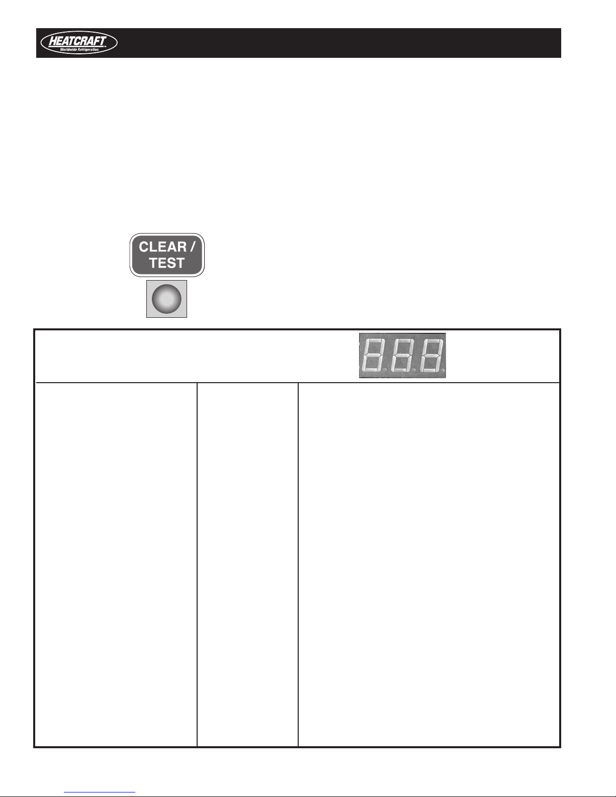
IMPORTANT NOTE:
When a board is installed and power is applied to the system, the following initialization steps should be taken for EACH BOARD in system:
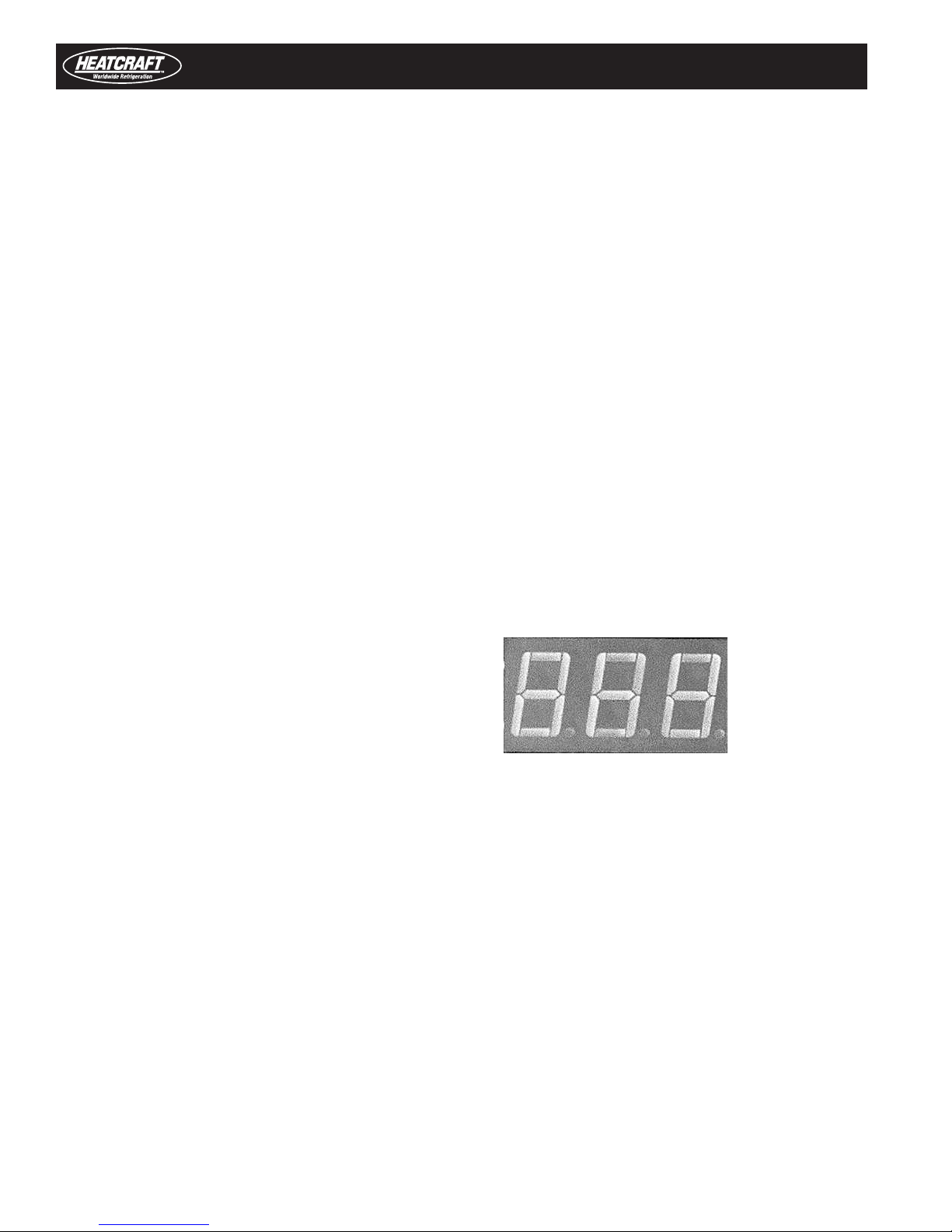
1. Press and Hold the "ENTER" button
2. While continuing to hold the "ENTER" button, press and hold the "CLEAR/TEST" button. "888" will display on the LED display.
3. Continue to hold both "ENTER" and "CLEAR/TEST" until "EE?" displays on the LED.
4. Once "EE?" displays, immediately release and the press the "ENTER" again.
5. The board will now re-initialize and return to the normal display.
If "nch" is displayed, then the board did not properly initialize and the steps 1-5 should be re-taken.
8
Programming & Reviewing
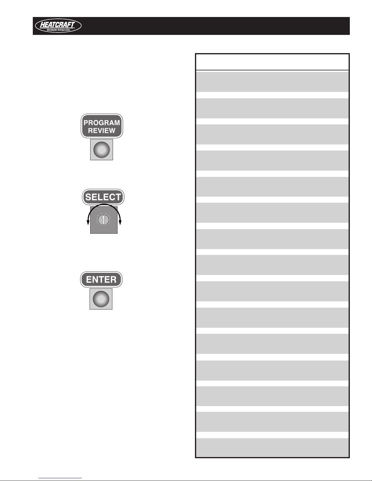
Programming And Reviewing Settings/Changes
The PROGRAM REVIEW button is used to program, review and
change all program settings for the system.
Press “PROGRAM REVIEW” button. The setpoint item will appear on
the LED. After a few seconds delay, the Setpoint value will display.
Each time the button is pressed a different setpoint item is displayed.
Next, use the “SELECT” knob to change value of setpoint item.
“PROGRAM REVIEW” ITEMS
A-E - Set Defrost type
(Air or ELE)
rEF - Set Refrigerant type (R-22, R-404A, R-507,
R-407A, R-407C, R-407F, R-448A or R-449A)
bot - Set Box temperature
(-30°F to +70°F)
SUP - Set Superheat
(4°F to 20°F)
SLA - Set Board as a Slave
(Yes or No)
Next, when the desired value is selected, press the “ENTER” button
to place it in program memory. If the “ENTER” button is not pressed,
the value will not be stored in the memory and thus will not be
changed.
ddF - Demand defrost enable (Yes or No)
dFn - Set Number of defrosts per day
(1, 2, 3, 4, 5, 6, 8,10 or 12 per day)
dFF - Set Defrost Fail-safe time
(10 to 200 minutes)
dFt - Set Defrost End temperature
(40°F to 100°F)
dFS - Set Defrost Delay Start Time
(0.5 Hours to 23.5 Hours)
ALH - Set Alarm High temperature
(-40°F to 90°F)
ALL - Set Alarm Low temperature
(-40°F to 90°F)
ALt - Set Alarm time
(2 to 120 minutes)
F-C - Set Fahrenheit / Celsius
temperature units (°F/°C)
FnS - Off cycle fan stir cycle enable (On or OFF)
9
Programming & Reviewing
Programming And Reviewing Settings/Changes (cont’d.)
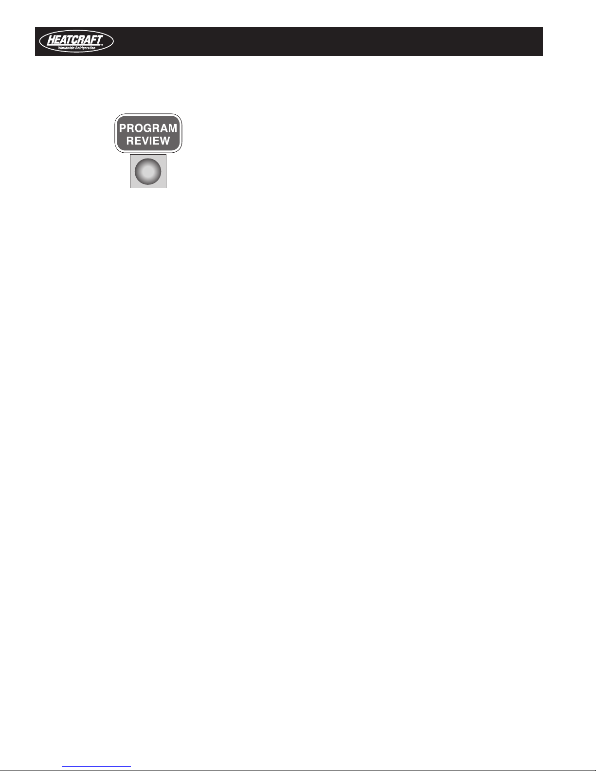
Use the “PROGRAM REVIEW” button to select these items:
• Defrost Type – “A-E” - Selection is made for air
defrost or electric defrost coil. This will automatically set
the system factory defaults for air defrost and electric
defrost. (See default settings.)
• Refrigerant Type - “rEF” - Selection for type of refrigerant
R-22 (22), R-404A (404), R-507 (507), R-407A (47A),
R-407C (47C), R-407F (47F), R448A (48A), R449A (49A).
• Box Temperature - “bot” - Select box temperature
setpoint. Selection range is -30°F to +70° F. Defaults:
Electric defrost -10°F and air defrost +35°F.
• Superheat - “SUP” - Evaporator superheat is controlled by
the board on each evaporator. Each board measures the
evaporator saturation suction temperature and the suction
pressure to determine the superheat. The superheat value
at the evaporator can be changed to ensure a 20°F to 30°F
superheat at the Compressor.
Default: 7°F.
• Evaporator Board: Slave? - “SLA” - On multiple evaporator
systems, each evaporator board has to be programmed
to be a Master or a Slave. Each board is shipped from our
factory set as a Master. You must make this change to
each Slave evaporator. A selection of “YES” is made for this
setting.
• Defrost fail-safe - “dFF” - This is the maximum time allowed
for a coil to remain in defrost. Defrost will be terminated if the
defrost end temperature is not attained when this time has
expired. On multiple evaporator systems, this is controlled by
the Master unit. Each board should have the same setting.
Defaults: electric defrost 30 minutes and air defrost 40 minutes.
• Defrost End Temperature - “dFt” - This is the temperature
at which the defrost will be terminated. Defaults: electric
defrost +60°F and air Defrost +45°F.
• Defrost Delay Start Time - “dFS” - This allows the delay of
the start of the first defrost. Default: 0.0 hours.
• Alarm High Temperature - “ALH” - Temperature at which a
high box temperature alarm will be triggered. This does not
apply during defrost. Defaults: electric defrost +5°F and air
defrost +50°F.
• Alarm Low Temperature - “ALL” - Temperature
at which a Low Box Temperature alarm will be
triggered. Defaults: Electric Defrost -15°F and Air
Defrost +30°F.
• Alarm Time - “ALt” - Time which High Temperature or
Low Temperature condition must exceed before alarm is
triggered. Default: 60 minutes.
The default for each board is a Master, so on Single
Evaporator systems no change is required.
• Demand Defrost Enable –“ddF” – Demand defrost is
available for electric defrost systems only. Selection is
made to enable demand defrost by a selection of “Yes” or
to not enable demand defrost by a selection of “No”. If this
parameter is enabled then parameters dFn and dFS will no
longer be displayed in the menu as they are no longer used.
Default: electric defrost Yes
• Number. of Defrost per Day - “dFn” - A selection must
be made for the number of defrosts cycles per day –
1,2,3,4,5,6,8,10 or 12 per day. If no selection is made,
defaults: electric defrost 4 per day and air defrost 2 per day.
10
• °F/°C - “F-C” - Select units to display temperature.
Fahrenheit or Celsius. Default: Fahrenheit. When °C is
selected, a red dot will appear in the right bottom corner of
the LED display of the Heatcraft Quick Response Controller
board.
• Off cycle fan stir cycle enable – “FnS” – This allows
evaporator fan stir cycling in the off cycle utilizing a
fixed stir cycle timing of 7 minutes on and 5 minutes off.
Selection is made to enable off cycle stir cycling by a
selection of “On” or to not enable off cycle stir cycling by
a selection of “Off”. Defaults: electric defrost off and air
defrost off
Programming & Reviewing
MONITOR
Use the “MONITOR” button to review these items:
SUP - Superheat
(°F/°C)
Use this button to “FORCE DEFROST”. To force a defrost, press the
“FORCE DEFROST” button. The system will pumpdown. The heaters
are then turned on. The display will show “dEF” and room temp.
FORCE
DEFROST
ESP - Expansion valve steps
(0 to 255 steps)
SCt - Suction temperature
(°F/°C)
SSt - Saturated Suction temperature
(°F/°C)
SCP - Suction pressure at Evaporator
(PSIG/HG)
Odt - Outdoor temperature
(°F/°C)
dFt - Defrost sensor temperature
(°F/°C)
dFS - Time left until next defrost
(hours) (on version 1.8 boards)
dFE - Last Defrost Elapsed time
(minutes)
AC - Board Voltage
SPt - Spare Temperature reading
Use this button to “RESET TIME”. Pressing this button will reset the
time clock in the microprocessor to zero. At initial power up, pressing
this button will bypass the “four minute” hold-off and the system will
start immediately after the expansion valve opens. This display will
show “dLy”.
RESET
TIME
Use this button to “FORCE SERVICE”. Pressing this button TWICE
will cause the system to pumpdown. The system will remain off until
the “CLEAR” button is pressed. While in the “FORCE SERVICE”, the
LED display will only show “SEr”.
FORCE
SERVICE
rEL - Software release program
11
Programming & Reviewing
Programming And Reviewing Settings/
Controller Board
Changes (Cont’d.)
Use this button to “CLEAR/TEST”. Pressing this button ONCE will
return the LED display to the default display. With the system in the
OFF mode, pressing and holding this button will start the “TEST”
mode. In the “TEST” mode, it will cycle through each output for 10
seconds. The display will only show “tst” during “TEST” mode. Test
mode will automatically terminate after 3 sequences.
Locking The Heatcraft Quick Response
The Heatcraft Quick Response Controller board is lockable to prevent
programmed setting changes by unauthorized personnel. When
locked, the program setpoints cannot be changed.
To lock the setting:
• Press “PROGRAM REVIEW” button.
• Press and hold “MONITOR” button.
• While holding “MONITOR” button,
press “ENTER” button.
• The LED will display Loc.
This will prevent unauthorized personnel program changes. To
unlock, repeat steps above. LED will display “UnL”.
STATUS INDICATOR LED
A RED, three-digit , alphanumeric LED on the Heatcraft Quick Response
Controller board indicates status, alarms and error codes.
• OFF Box Temp / oFF Box Temperature/ Mode is displayed
All Evaporators
• COOLING
Single Evaporator- Box Temp /Coo Box Temperature/ Mode is displayed
Multiple Evaporators
Master Evap - Box Temp / Coo Box Temperature/ Mode is displayed
Slave Evaps - Coo Operating Mode is displayed
• Pumpdown
All Evaporators Pdn
• DEFROST
All Evaporators dEF
• TEST
All Evaporators tSt
• SERVICE
All Evaporators SEr
• ALARMS A 1 High Box Temp
A 2 Low Box temp
A 4 Input Fault
Box Temp., Suction Temp., Pressure
Transducer open or not installed
12
 Loading...