

Heatcraft FNE-D04-H272 Installation Manual
Bulletin H-IM-FN
FN Fluid Coolers
Installation and Maintenance Data
JAN 2015
Table of Contents
Inspection, System Warranty, Rigging Instructions 2
Installation Unit Location Sound 3
Location Constraints System Installation,
Piping Installation 4
Glycol Charge 5
Typical Piping 6
Mixing Glycol and Water Glycol Sludge Prevention
Fluid Circulating Pump 7
Start-up Space and Location Requirements 8
Fan Cycling and Fan Speed Controls 9
Typical Wiring Diagrams 13
Physical and Electrical Data 17
In- Warranty Return Material Procedure
Replacement Parts 24
Nomenclature
F N H S 04 H 2 03
Model Vintage Motor Width Fans Tube Diameter Number of Rows Coil Slab
F =
Fluid Cooler
H = 1140 RPM 1.5 HP
L = 830 RPM 1.5 HP
Q = 540 RPM 0.5 HP
E = VSEC Motor
S = Single
D = Double
01 - 12 Fans H = 1/2”
F = 5/8”
Inspection and Handling
Responsibility should be assigned to a dependable individual at the job site to receive material. Each shipment should be carefully checked against the
bill of lading accounting for all items. Shipment should be carefully checked for damage including concealed damage. Any shortage or damages should
be reported to the delivering carrier. Damaged material becomes the delivering carrier's responsibility, and should not be returned to the manufacturer
unless prior approval is given to do so.
When uncrating, care should be taken to prevent damage. Rough handling, impacts and drops should be avoided. Do not push or pull on unit. Heavy
equipment should be left on unit’s shipping base until it has been moved to the final location.
System Warranty
This equipment is designed to operate properly and produce rated capacity when installed in accordance with accepted industry standards. Failure to
meet the following conditions may result in voiding of the system warranty:
1. System piping must be installed following industry standards for good piping practices.
2. Inert gas must be charged into piping during brazing or welding.
3. System must be thoroughly leak checked before initial charging.
4. Power supply to system must meet the following conditions:
a. Voltage for 208/230 motors not less than 195 volts or more than 253 volts.
b. All other voltages must not exceed +/- 10% of nameplate ratings.
c. Phase imbalance not to exceed 2%.
5. All controls and protection circuits properly connected per wiring diagram.
6. Factory installed wiring must not be changed without written factory approval.
System Installation
NOTE: Installation and maintenance to be performed only by qualified personnel who are familiar with local codes and regulations, and experienced
with this type of equipment.
CAUTION: Sharp edges and coil surfaces are a potential injury hazard. Avoid contact with them.
Warning: Improper lifting or moving unit can result in severe personal injury or death. Follow rigging and moving instructions carefully.
General
1. Unit must be properly located and supported.
2. Level mounting is necessary to assure proper fluid distribution through the coil as well as flooded suction for the pump.
3. Water piping must comply with local codes. Correct pipe sizing and layout will help reduce pumping power and operating costs.
4. In case of doubt, contact factory for the dry cooler fluid pressure drop at the specific conditions on your job.
5. Provide sufficient valves and unions to permit easy access to parts subject to wear and possible repair or replacement.
6. After fluid piping is completed, all joints should be leak tested.
7. Select wire in accordance with nameplate data and local codes.
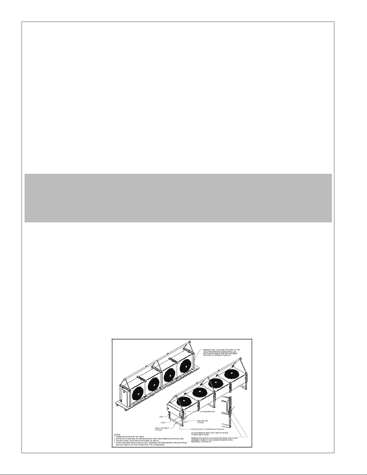
Unit Rigging
1. Spreader bar must be used for all rigging.
2. Under no circumstance should coil connections, coil headers, return bends, or electrical box be used in lifting or moving the fluid cooler.
3. Under no circumstance should any person be under the fluid cooler.
4. If there are more than four lifting points on the fluid cooler, more than four lifting points should be used.
4. Under no circumstance should the fluid cooler lifting points be used to lift a fluid cooler that has been attached to other equipment, like a steel frame.
If fluid cooler has been attached to other equipment, use lifting points provided on other equipment to lift complete assembly.
Figure 1. Rigging Instructions.
2
© Heatcraft Inc. 2015.
Unit Location
Units are designed for outdoor application and may be installed on a roof or at ground level. Roof mounted units should be installed level on steel
channels or an I-beam frame to support the unit above the roof. Provide suitable flashing of the roof. Use of vibration pads or isolators is recommended.
Ground mounted units should be installed on concrete slabs that are level and properly supported to prevent settling. A one-piece concrete slab with
footings extending below the frost line is recommended. Structure supporting unit must be designed to support the weight of both the unit and the
fluid. Table 1 provides weight of fluid per gallon. Tables 4 thru 7 provide unit weight and volume data. The unit needs to be secured in its final location.
Holes are provided in the base runner for this purpose.
The most important considerations which must be taken into account when deciding upon the location of air-cooled equipment are the provision for a
supply of ambient air to the fluid cooler and the removal of heated air from the fluid cooler area. Failure to meet these requirements will result in loss
of capacity and possible eventual failure of equipment. Units must not be located in the vicinity of steam, hot air or fume exhausts. Also keep unit fan
discharge away from any building air intakes. Do not attach ductwork to the coil inlet or fan outlet. The dry cooler should be located far enough away
from any wall or other obstruction to provide sufficient clearance for air entrance. Care should be taken to avoid air recirculation conditions that can be
caused by sight screening, walls, etc. See page 4 for space and location requirements.
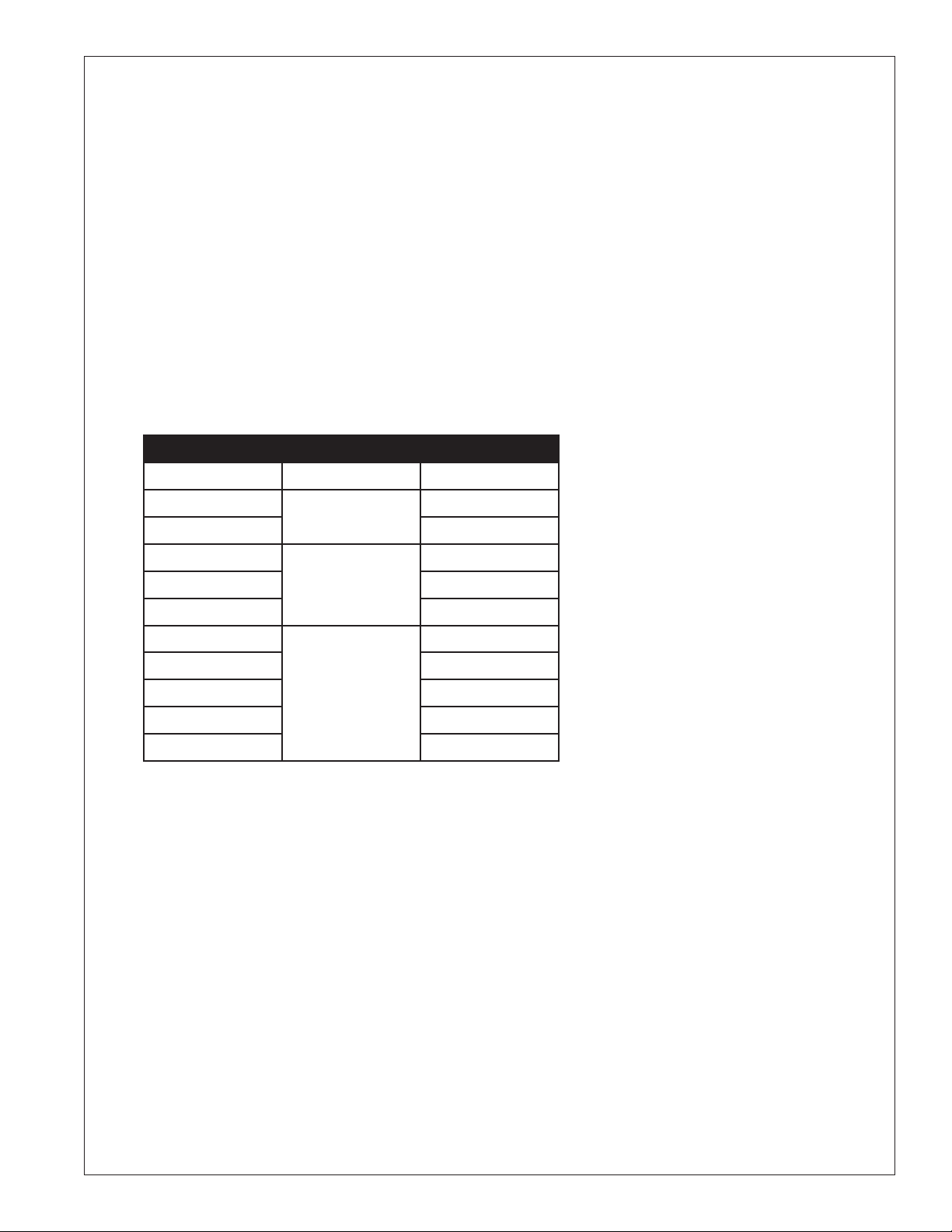
Table 1. Fluid Weight Per Gallon
0% Glycol Fluid Type Lbs. Per Gallon
0
10
20
30
40
50
10
20
30
40
50
Water 8.22
8.36
8.49
Ethylene Glycol 8.61
8.73
8.84
8.32
8.40
Propylene Glycol 8.45
8.50
8.54
Sound Vibration
Units should be installed away from occupied spaces to reduce the transmission of sound or vibration into the occupied space. Units should be installed
above or outside non occupied spaces like utility areas, corridors and auxiliary spaces to reduce sound and vibration transmission to occupied spaces.
The fluid piping should be flexible enough to prevent the transmission of noise and vibration from the unit into the building. If the fluid lines are to be
suspended from the structure of the building, isolation hangers should be used to prevent the transmission of vibration. Where piping passes through a
wall, it is advisable to pack fiberglass and sealing compound around the lines to minimize vibration and retain flexibility in the lines.
3
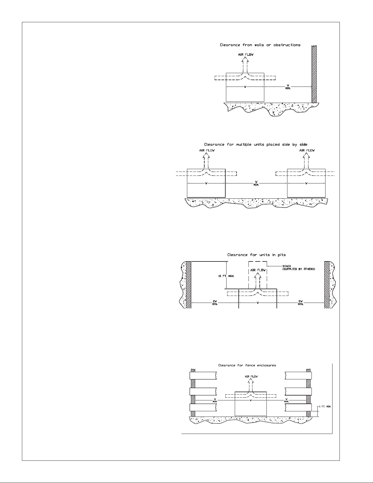
Walls or Obstructions
The unit should be located so that air may circulate freely and not be recirculated. For proper air flow and access all sides of the unit should be
a minimum of “W” away from any wall or obstruction. It is preferred that
this distance be increased whenever possible. Care should be taken to
see that ample room is left for maintenance work through access doors
and panels. Overhead obstructions are not permitted. When the unit is in
an area where it is enclosed by three walls the unit must be installed as
indicated for units in a pit.
Multiple Units
For units placed side by side, the minimum distance between units is
the width of the largest unit. If units are placed end to end, the minimum
distance between units is 4 feet
Units in Pits
The top of the unit should be level with the top of the pit, and side
distance increased to “2W”. If the top of the unit is not level with the top
of pit, dis- charge cones or stacks must be used to raise discharge air to
the top of the pit. This is a minimum requirement.
Decorative Fences
Fences must have 50% free area, with 1 foot undercut, a “W” minimum
clearance, and must not exceed the top ofunit. If these requirements are
not met, unit must be installed as indicated for “Units in pits".
* “W” = Total width of the fluid cooler
4
Electrical Wiring
The electrical installation should be in accordance with National Electrical Code, local codes and regulations. Proper overcurrent protection should
be provided for the fan motors. Wiring diagrams shown are only basic and do not show fuses, additional disconnect switches, etc., which must be
provided in the field.
Units have a through the door disconnect mounted in the electrical box.
All standard motors have internal inherent overload protectors. Therefore, contactors can be used instead of starters requiring thermal protectors,
eliminating the problem of furnishing the proper heating elements.
Electrical leads from each motor terminate at the unit junction box. Field connections must be made from these leads in accordance with local,
state and national codes.
Three-phase motors must be connected to three-phase power of voltage to agree with motor and unit data plate.
The motors are wired into a common junction box. The motors must be checked for proper rotation. Be sure to check that motor voltage and control
connection agree with electric services furnished.
Piping Installation
The piping system should provide maximum leak prevention. Weld or sweat joints should be used where possible or either tightly drawn Teflon tape
threaded pipe joints or properly gasketed flanged connections should be made if needed. Flange gaskets should be compatible with fluid being used.
The glycol system should not employ a pressure reducing valve. This is because a slight leak would lead to dilution of the mixture. Any refill should
be controlled so as to maintain the proper glycol-to-water ratio.
Table 2 shows pressure drops for various pipe sizes at flow rates commonly used with a typical dry cooler. These pipe sizes are not necessarily
always correct for the run from the condenser to the dry cooler. Proper pipe size will depend on available pump head. This can be determined by
subtracting from the total available pump head at design flow, the process equipment pressure drop and the dry cooler pressure drop. Allow some
safety factor for pipe fittings added to the system and for eventual fouling of the system.
a. Glycol piping requires no insulation except when fluid temperature will be below ambient dewpoint temperatures.
b. Vents are required at all high points in the piping to bleed air when filling the system. If fluid coolers are at high points, vent valves
should be installed at each fluid cooler.
c. It is recommended that gate valves be installed on both sides of the pump to prevent loss of fluid in the event the pump should require
repair or replacement. Shut-off valves are also recommended at the process equipment in case the equipment is to be moved or
requires maintenance involving the coolant system.
Table 2. Pressure Loss in Feet of Water
Flow GPM Pipe Size
Steel
15
20
25
25
30
35
40
40
45
60
60
80
100
150
200
250
300 3
300
350
400
1
1
1
1 1/4
1 1/4
1
1
-
1
1
1 1/
2
2
1
2
2 1/
3
3
1
4
4
4
/
4
/
2
2
/
2
2
/
2
Type “L” O.D.
Copper
1 1/8
1 1/8
1 1/8
1 3/8
1 3/8
3
8
/
1
8
1 3/
1 5/
8
1 5/
8
1 5/
8
1
/
2
8
2 1/
8
2 5/
8
2 5/
8
3 1/
8
3 1/
8
3 5/
8
1
4
/
8
4 1/
8
4 1/
8
Schedule 40 Steel Head
Ft./100 Ft. Equiv. Length
17.6
30.2
—
11.5
16.3
21.8
13.0
16.5
—
7.9
13.7
8.5
18.6
10.7
16.5
11.1 9.2
5.9
7.9
10.2
CCopper Tube Head
Head Ft./100 Ft.
Equiv. Length
15.0
23.1
34.6
12.6
17.4
23.0
26.3
12.9
15.7
26.3
7.0
12.0
6.1
12.9
9.1
13.7
4.9
6.5
8.2
5
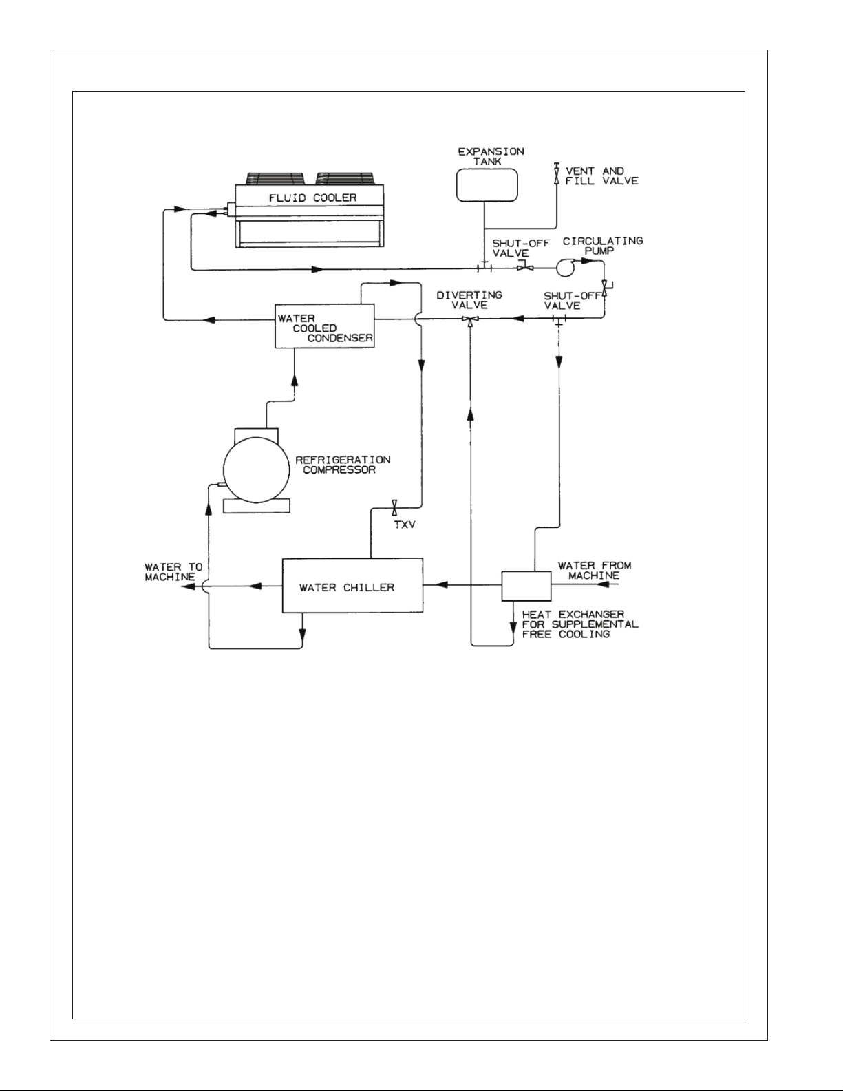
Diagram 1. Typical Piping
6
Glycol Charge
The amount of glycol required depends upon the following:
a. The holding volume of the system which includes the holding capacity of the process equipment, the holding capacity of the
interconnecting piping and the holding capacity of the dry cooler.(see Table4-7)
b. Percentage of glycol required by volume to provide protection at the design minimum outside temperature (see Table 3).
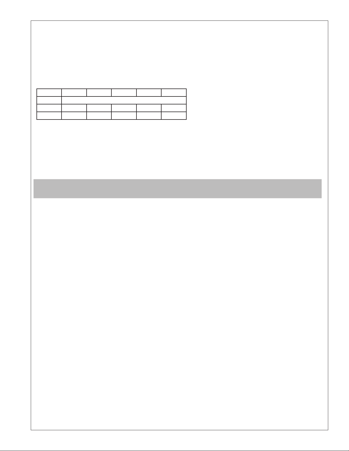
Table 3. Freeze Protection - Percentage of Glycol to be Added by Volume.
Percent % 20% 30% 40% 45% 50%
0
Glycol Type Minimum Outside Design Temperature
Ethylene +16 +4 -13 -23 -35
Propylene +18 +8 -7 -17 -29
Table 3 is intended to be used as a guide only. Proper precautions need to be taken to prevent freeze damage during low ambients. Consult glycol vendor
recommendations for specific freeze protection for your location.
F
Mixing Glycol and Water
Regardless of the strength of the mixture, you MUST pre-mix the glycol and water prior to adding it to the system. The chemical reaction between the
two will release oxygen, which is extremely undesirable in a close-loop system.
WARNING: For dry coolers operating without glycol mixture, adequate freeze protection is necessary during ambients below 320F.
Glycol Sludge Prevention
Glycol systems may be subject to sludge formation in coils, due to one or more of the following causes:
1. Reaction of the corrosion inhibitor with galvanized piping (zinc).
2. Reaction of the glycol with chromate type water additives.
3. Reaction of the glycol with pipe dope, cutting oils, solder flux, and other system dirt.
Glycol manufacturers offer a specially inhibited glycol (formulated for snow melting systems) which does not react with zinc. This glycol is also suitable
for heat transfer systems. Glycol manufacturers also provide inhibitor check services on a regular basis.
Consequently, good glycol system design requires the following precautions:
1. No galvanized piping is to be used.
2. System piping must be thoroughly cleaned and flushed before filling with the water/glycol mixture.
3. No chromate inhibitor treatment must be used.
4. The glycol manufacturer should provide inhibitor check service and supply additional inhibitor as required.
Fluid Circulating Pump
Mechanical seal type pumps must be used for glycol systems. Gland type pumps would cause glycol waste and, if used with a pressure reducing valve,
will lead to dilution of the glycol mixture and eventual freeze-up.
Pump is selected for piping friction loss plus fluid pressure drop through the dry cooler coil, plus pressure drop through the heat source. No allowance
for vertical lift is made since in a closed system a counterhead acts on the pump suction. Pumps motor should be non overloading where possible.
Paralleled pumps can also be used for good power economy and continuous and automatic standby operation. Properly applied parallel pumps will
guard against system breakdown caused by a simple pump failure.
7
Start-up
Prestart:
1. Check that power supplies match unit nameplate.
2. Check all electrical and fluid connections to make sure the connections are tight.
3. Check that fans and motor mount connections are securely tightened.
4. Check for correct fan rotation. Fans should draw air thru the coil surface. Be sure that the fans run freely.
5. Thoroughly leak check all system piping.
6. Check for correct pump rotation.
7. Check fan controls and adjust if necessary.
Filling and Purging the System
The system should be pressure tested before adding glycol. The system can be tested with air or water, however if the ambient temperature is at or
below freezing the use of air is recommended. Test pressure should not exceed 60 PSIG.
a. Roof Mounted Fluid Cooler
To fill the system, pour the premixed water and glycol into the expansion tank. Fill the system until the expansion tank is half full and then
purge the air from ALL vents. Operate the system for a minute, then purge ALL vents again and add glycol as required. Repeat the purging
of all vents after the first hour of operation and again after several hours of operation.
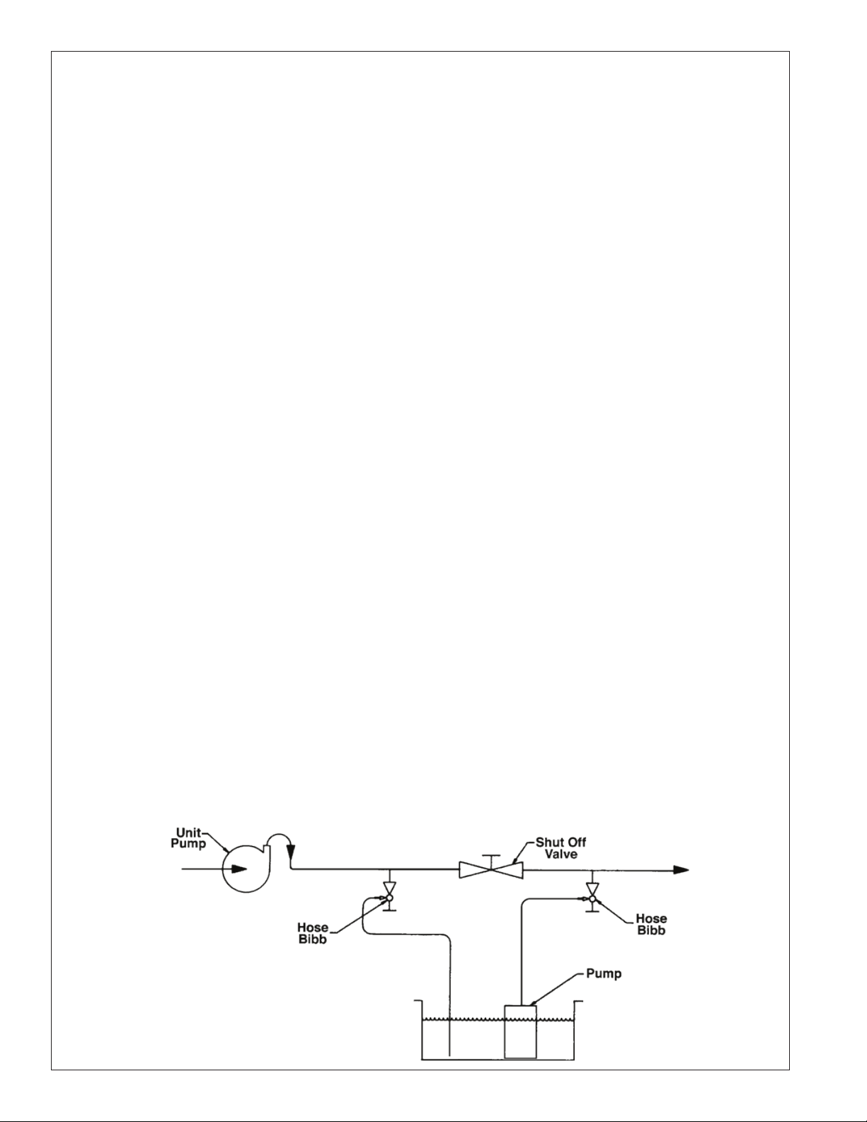
b. Ground Mounted Fluid Cooler
The fluid cooler may be lowest point in the system; consequently the premixed water and glycol will have to be pumped into the system.
Close the shut off valve and open the two hose bibbs installed in the piping run on the leaving side of the pump, see piping diagram.
Connect a pump and hose to the hose bibb away from the pump and a hose to the hose bibb closest to the pump. Begin pumping the
glycol mixture into the system at FULL PRESSURE. For the return hose you should close the hose bibb so that you get only a small flow of
fluid or air. This is necessary so you will build a head of fluid which will force the air from the system. Once all the air is out you will have a
steady flow of only fluid. At this point you should close off the two hose bibbs and open the shut off valve. See Diagram 2.
Flow Adjustment Procedure:
Once the system is completely full of fluid, start the fluid circulating pump. To assure proper fluid flow, adjust the shut-off valve for required GPM by
checking pump curve and observing gauge pressure, or by using an in-line flow meter.
Instruction Envelope:
Keep wiring diagrams and installation/operation manual, in an envelope within easy reach of the installed dry cooler.
Diagram 2.
8
 Loading...