

Page 1
OWNER’S MANUAL
Inverter Single Zone
Ductless Mini Split Heat Pump
VMH 30/36 Series
Version C
Heat Controller, Inc. • 1900 Wellworth Ave. • Jackson, MI 49203 • (517)787-2100 • www.heatcontroller.com
Page 2
Owner’s Manual VMH 30/36 SERIES Heat Controller, Inc.
CONTENTS
DISPOSAL: Do not dispose this product as unsorted municipal waste. Collection
of such waste separately for special treatment is necessary.
It is prohibited to dispose of this appliance in domestic household waste.
For disposal, there are several possibilities:
A) The municipality has established collection systems, where electronic waste can
be disposed of at least free of charge to the user.
B) When buying a new product, the retailer will take back the old product at least
free of charge.
C) The manufacture will take back the old appliance for disposal at least free of
charge to the user.
D) As old products contain valuable resources, they can be sold to scrap metal
dealers.
Wild disposal of waste in forests and landscapes endangers your health when
hazardous substances leak into the ground-water and find their way into the food
chain.
When using this air conditioner in the European countries, the following
informations must be followed:
Installation work must be performed in accordance with local and national electrical codes
CONTENTS
SAFETY PRECAUTIONS
Warning ..................................................................................................................................3
Caution ...................................................................................................................................4
OPERATING INSTRUCTIONS
Identification of parts .............
LED display features ..............................................................................................................6
Operating conditions...........................................................................................................7
Manual operation .................................
Airflow direction control ..........................................................................................................8
Operational modes ................................................................................................9
CARE AND MAINTENANCE
Care and maintenance .....................................................
OPERATION TIPS
Operation tips ............ ..........................................................................................................12
TROUBLESHOOTING TIPS
Troubleshooting tips .............................................................................................................14
..............................................................................................5
...................................................................................7
.....................................................10
CAUTION
Contact an authorized service technician for repair or maintenance of this unit.
Contact the authorized installer for installation of this unit.
If the power cord is to be replaced, replacement work shall be performed by
authorized personnel only.
by authorized personnel only.
2
Page 3
Heat Controller, Inc. VMH 30/36 SERIES Owner’s Manual
SAFETY PRECAUTIONS
It may cause an injury.
When the air filter is to be
removed, do not touch the
metal parts of the unit.
Do not clean unit when
power is on as it may cause
fire and electric shock, or
injury.
When the unit needs to be
cleaned, switch off, and
turn off the circuit breaker.
Appearance may be
deteriorated due to change
of product color or
scratching of its surface.
Do not clean with strong
detergants. Use a soft dry
cloth for cleaning.
!
Operation without filters
may cause failure.
Always insert the filters
securely. Clean filter
once every two weeks.
!
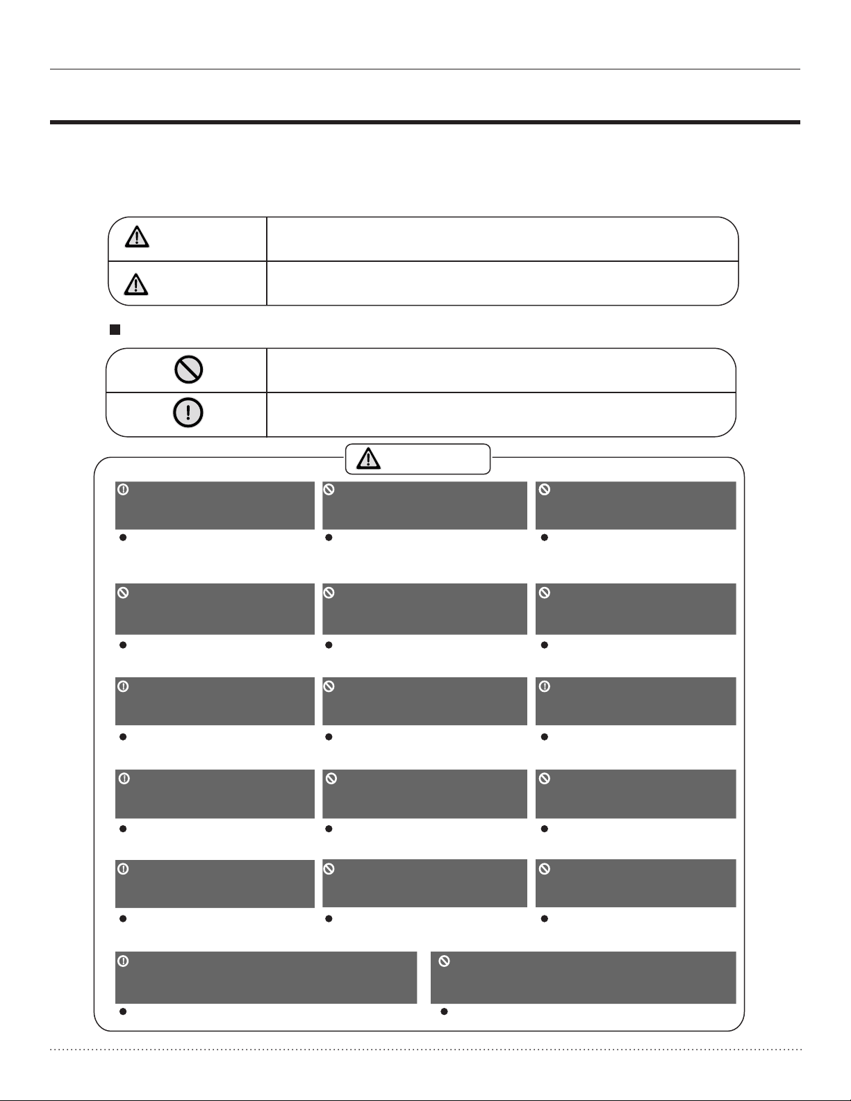
SAFETY PRECAUTIONS
To prevent injury to the user or other people and property damage, the following instructions
must be followed. Incorrect operation due to ignoring the instructions may cause harm or damage.
The seriousness is classified by the following indications:
WARNING
CAUTION
This symbol indicates the possibility of death or serious injury.
This symbol indicates the possibility of injury or damage to property.
Meanings of symbols used in this manual are as shown below:
Never do this.
Always do this.
WARNING
!
Connect the power properly,
following all local and national
electric codes.
Otherwise, it may cause
electric shock or fire due to
excess heat generation.
Do not modify power cord
length or share the outlet
with other appliances
It may cause electric shock
or fire due to heat generation.
! !
Always ensure proper
electrical grounding.
No grounding may cause
electric shock.
!
Disconnect the power if
strange sounds, smells, or
smoke comes from the unit.
It may cause fire and
electric shock.
!
Use the correctly rated
breaker or fuse.
Do not operate or stop the
unit by switching on or off
the power.
It may cause electric shock
or fire due to heat generation.
Do not operate with wet
hands or in damp
environment.
It may cause electric shock.
Do not allow water to get
into electric parts.
It may cause failure of
machine or electric shock.
Do not drink water drained
from air conditioner.
It contains contaminants and
could make you sick.
Do not use the power cord
close to heating appliances.
Do not damage or use an
unspecified power cord.
It may cause electric shock
It may cause electric shock
or fire.
or fire.
Do not direct airflow at room
occupants only, allow air to
disperse into the room.
This could damage your
health.
Always install circuit
breaker and a dedicated
power circuit.
No installation may cause
fire and electric shock.
Do not open the unit
during operation.
It may cause electric shock.
Do not disassemble or
modify unit.
There is risk of fire or
electric shock.
!
Ventilate room before operating air
It may cause fire and
electric shock.
conditioner if there is a gas leakage
from another appliance.
It may cause explosion, fire and, burns.
It may cause failure and
electric shock.
Do not use the appliance near
flammable gas or combustibles, such
as gasoline, benzene, thinner, etc.
It may cause an explosion or fire.
3
Page 4
Owner’s Manual VMH 30/36 SERIES Heat Controller, Inc.
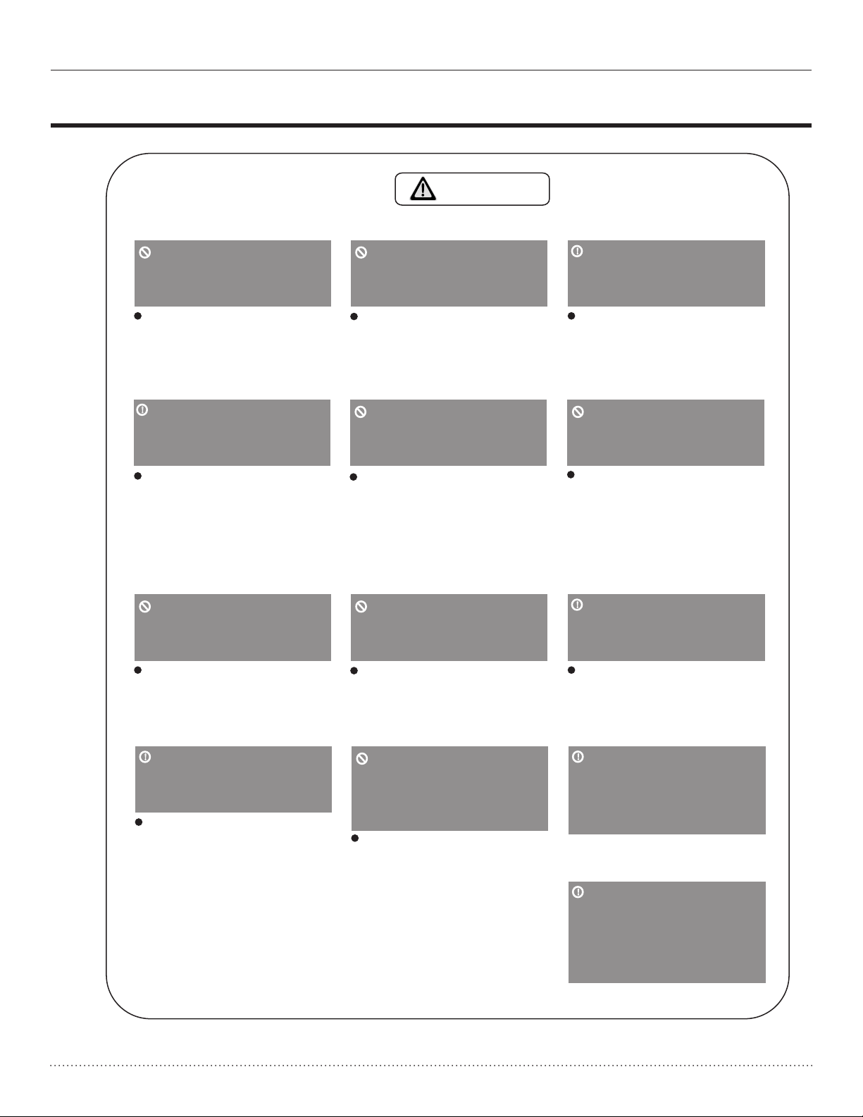
SAFETY PRECAUTIONS
SAFETY PRECAUTIONS
CAUTION
When the air filter is to be
removed, do not touch the
metal parts of the unit.
It may cause an injury.
!
When the unit needs to be
cleaned, switch off, and
turn off the circuit breaker.
Do not clean unit when
power is on as it may cause
fire and electric shock, or
injury.
Do not clean with strong
detergants. Use a soft dry
cloth for cleaning.
Do not clean the air
conditioner with water.
Water may enter the unit
and degrade the insulation.
It may cause an electric
shock.
Do not put a pet or house
plant where it will be
exposed to direct air flow.
This could injure the pet or
plant, allow airflow from
appliance to disperse into
the room.
Do not place obstacles
around air-inlets or inside
of air-outlet.
!
Ventilate the room well
when used together
with a stove, etc.
An oxygen shortage may
occur.
Do not use for special
preservation purposes.
Do not use this air conditioner to preserve precision
devices, food, pets, plants,
and art objects. It may
cause deterioration of
quality, etc.
!
Turn off the main power
switch when not using
the unit for a long time.
Appearance may be
deteriorated due to change
of product color or
scratching of its surface.
!
Always insert the filters
securely. Clean filter
once every two weeks.
Operation without filters
may cause failure.
It may cause failure of
appliance or accident.
Do not place heavy object
on the power cord and
take care so that the cord
is not compressed.
There is danger of fire or
electric shock.
4
It may cause failure of
product or fire.
!
Use caution when
unpacking and installing.
Sharp edges could cause
injury.
!
If water enters the unit,
turn the unit off and
disconnect the power,
contact a qualified service
technician.
Page 5
Heat Controller, Inc. VMH 30/36 SERIES Owner’s Manual
OPERATING INSTRUCTIONS OPERATING INSTRUCTIONS
Identification of parts
LED display features
Signal
receptor
Signal
receptor
Signal
receptor
Signal
receptor
The actual display on your appliance may
differ slightly, but the features and
functions still apply:
OPERATING INSTRUCTIONS
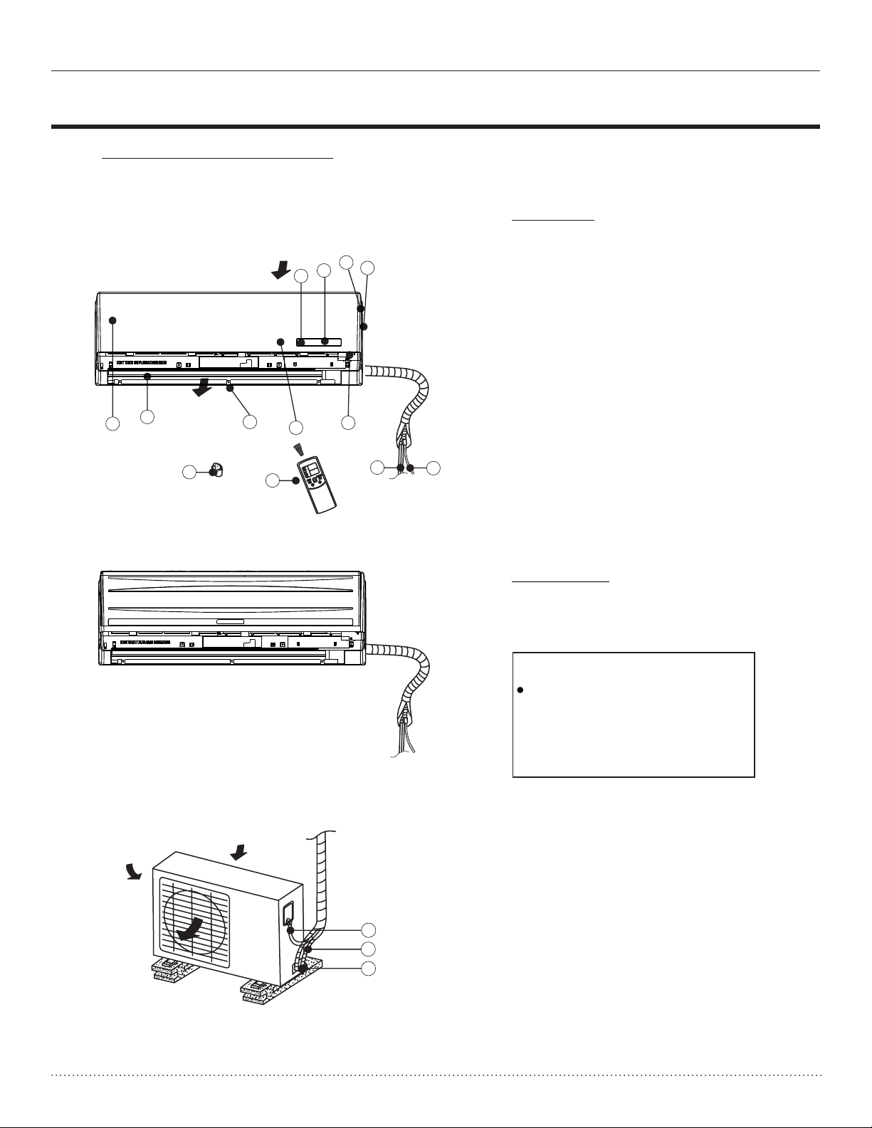
Indoor unit
Note: The indoor unit you purchased may look
like one of the following:
Air inlet
1
Air outlet
6
5
10
7
8
11
3
2
4
9
O
T
U
A
L
O
O
C
Y
R
D
T
A
E
H
D
E
E
P
S
N
N
A
A
F
F
E
D
O
M
M
12
13
Indoor unit
1. Signal receptor
2. Display panel
3. Panel frame
4. Chassis
5. Front panel
6. Horizontal louver
7. Vertical louver(on some models)
8. Air filter(under the panel)
9. Manual control button
10. Remote controller holder
11. Remote controller
12. Connecting pipe
13. Drain hose
Outdoor unit
Air inlet(side)
Air outlet
(A)
(B)
Air inlet(rear)
14
15
16
Outdoor unit
14.
Connecting cable
15. Connective pipe
16. Base valve
NOTE:
All the pictures in this manual
are for explanation purposes
only. Your air conditioner may
be slightly different.
5
Page 6
Owner’s Manual VMH 30/36 SERIES Heat Controller, Inc.
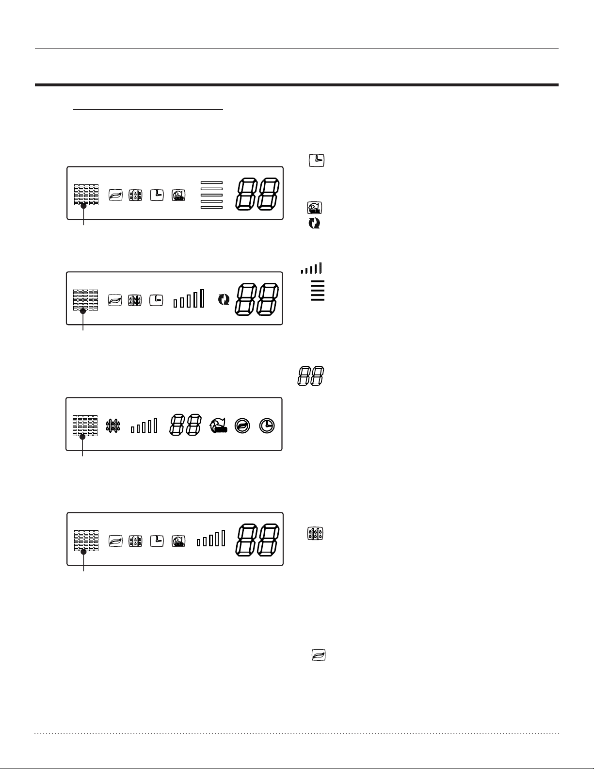
LED display features
OPERATING INSTRUCTIONS
The actual display on your appliance may
differ slightly, but the features and
functions still apply:
Signal
receptor
(1)
Signal
receptor
(2)
Signal
receptor
(3)
Signal
receptor
(4)
TIMER indicator
This indicator illuminates when
TIMER program is set ON/OFF.
AUTO indicator
This indicator illuminates when
the air conditioner is in AUTO
operation.
OPERATION FREQUENCY indicator
This display is separated into five zones.
The zones illuminate based on the
frequency of the compressor. For
example: high frequency will illuminate
all zones, the lower the frequency the
less zone will illuminate.
TEMPERATURE indicator
A) This displays the temperature
point. When set temperature is
changed, this indicator begins
to flash, and stops 20 seconds later.
B) In fan only mode, the temperature
indicator displays the room
temperature.
C) This may also display any error or
protection codes needed to trouble
shoot the problem.
DEFROST indicator
This indicato
r illuminates when the
air conditioner starts defrosting
automatically or when the warm air
control feature is activated in heating
operation.
CLEAN AIR indication lamp:
Lights up when CLEAN AIR feature
is activated.
6
Page 7
Heat Controller, Inc. VMH 30/36 SERIES Owner’s Manual
NOTE: This manual does not include Remote Contro ller Opera tions, see the
Airflow direction control
OPERATING INSTRUCTIONS
Range
Range
Vertical
louver
(three places)
OPERATING INSTRUCTIONS
Remote Controller Inst ruction ma nual packed with the unit for details.
Operating conditions
Temperature
Mode
Room temperature
Outdoor temperature
O O O O
5 F~122 F (-15 C~50 C)
Cooling
Operation
O O
≥62 F(17 C)
O O
32 F ~ 122 F
O O
(0 C ~ 50 C)
≤88 F(30 C)
(-15 C ~ 34 C)
For the models with low
ambient controls.
CAUTION:
1. Optimum performance will be achieved within these operating temperatures.
2
. If air conditioner is used outside of the above conditions, certain safety protection
features may come into operation and cause the unit to function abnormally.
. If the air conditioner operates in excess of 80% relative humidity, the surface of the air
3
conditioner may attract condensation. Please set the vertical air flow louver to its
maximum open angle (vertically to the floor), and set the fan to HIGH mode.
Sugges
temperature is below 0 C), we strongly recommend you to keep the machine
tion: For units with crankcase heaters when the outside ambient
O
O
32 F(
plugged in order to guarantee it running smoothly.
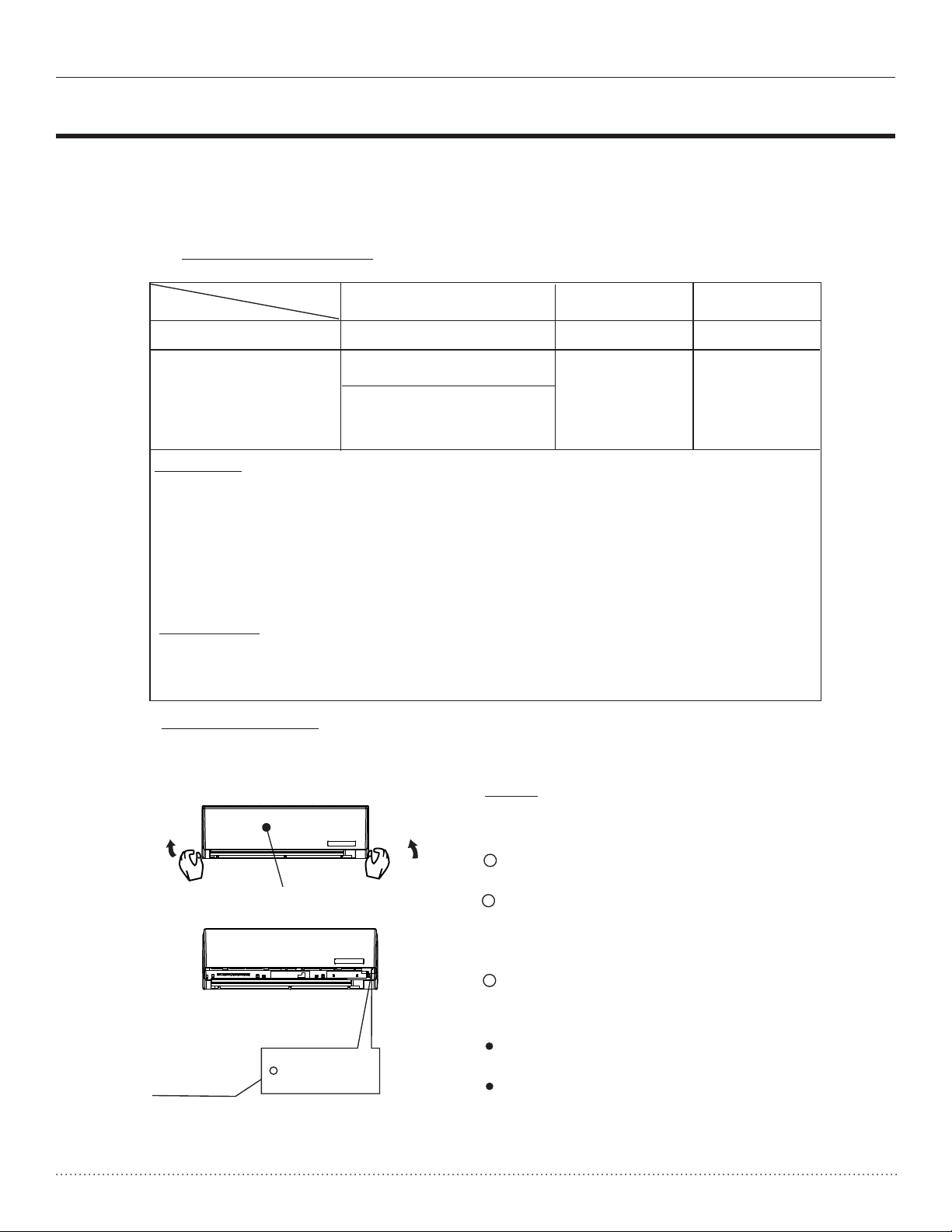
Manual operation
Heating
Operation
O O
O O
5 F ~ 92 F
O O
Drying
Operation
O O
>50 F(10 C)
O O
5 F ~ 122 F
O O
(15 C ~ 50 C)
Manual operation can be used temporarily in case the remote controller is disabled or
when maintenance is necessary.
NOTE: The unit mus t be turned off befor e
using the manual control button. If the
unit is operational, continue pressin g the
manual control button until the unit is off.
Open and lift the front panel up to an angle
1
until it remains fixed with a clicking sound.
Front panel
2
One press of the manual control button will
lead to forced AUTO operation. If press
the button twice within five seconds, the unit
will operate under forced COOL operation.
3
Close the panel firmly to its original
position.
CAUTION:
This button is used for testing purposes only.
Manual control
button
AUTO/COOL
To restore the remote controller operation,
use the remote controller directly to operate
the unit. This will override the manual
operation.
7
Page 8

Owner’s Manual VMH 30/36 SERIES Heat Controller, Inc.
OPERATING INSTRUCTIONS
OPERATING INSTRUCTIONS
Airflow direction control
Range
Vertical
louver
(three places)
Adjust the air flow direction properly otherwise, it
might cause discomfort or uneven room
temperatures.
Adjust the horizontal louver using the remote
controller.
Adjust the vertical louver manually.
To set the vertical air flow(Up--Down) direction
Perform this function while the unit is in operation.
Use the remote controller to adjust the air flow
direction. The horizontal louver can be moved at
a range of 6 for each press, or swing up and down
automatically depending on model. Please refer to the
REMOTE CONTROLLER OPERATION MANUAL that
come with your unit for details.
To set the horizontal air flow direction (left - right)
Move the vertical louver manually to adjust the air flow
in the direction you prefer.
IMPORTANT: Before adjusting the vertical louvers, the
supply power must be disconnected to prevent electrical
shock or injury.
For some models, the vertical louver can be adjusted
by using the remote controller. Please refer to the
REMOTE CONTROLLER OPERATION MANUAL
that comes with your unit for details.
O
Range
CAUTION
Do not operate the air conditioner for long periods with
the air flow direction set downward in cooling or
dehumidifying mode. Otherwise, condensation may
occur on the surface of the horizontal louver causing
moisture to drop on to the floor or on furnishings.
Do not move the horizontal louver manually unless it is
necessary. Always use the remote controller, where
applicable.
When the air conditioner is started immediately after it
was stopped, the horizontal louver might not move for
approximately 10 seconds.
Open angle of the horizontal louver should not be set
too small, as COOLING or HEATING performance may
be impaired due to too restricted air flow area.
Do not operate unit with horizontal louver in closed
position.
When the air conditioner is connected to power (initial
power), the horizontal louver motor may generate a
sound for 10 seconds, this is a normal occurance.
8
Page 9

Heat Controller, Inc. VMH 30/36 SERIES Owner’s Manual
Care and maintenance
OPERATING INSTRUCTIONS
Cleaning the air filter
OPERATING INSTRUCTIONS
Operational modes
AUTO operation
When you set the air conditioner to AUTO mode, it will
automatically select cooling, heating or fan only
operation depending on what temperature you
have set and the current room temperature.
The air conditioner will control room temperature
automatically around the temperature set point you
selected.
If the AUTO mode is uncomfortable, you can select
desired conditions manually by changing the mode to
cooling, heating, or fan only directly.
SLEEP operation
SLEEP operation
Set
Temperature
1 hour
Cool ing
SLEEP operation
Set
Temperature
1 hour
Heating
7 hours timer off
1 hour
7 hours timer off
1 hour
SLEEP operation
When you push SLEEP button on remote controller
during cooling, heating, or AUTO operation, the air
conditioner will automatically increase (cooling) or
decrease (heating) per hour for the first 2
O O
2 F/1 C
hours, then hold steady for the next 5 hours, after that
it will switch off. This characteristic maintains both
energy saving and comfort in night operation.
DRYING operation
The fan speed will be automatically controlled under
dry operation.
During the dry operation, if the room temperature is
lower than 50 F( , the compressor stops operation
and restarts when the room temperature is above
54 F( .
O
O
12 C)
O
O
10 C)
Optimal operation
To achieve optimal performance, please note the
following:
Adjust the air flow direction correctly so that it is not
directed on people, but rather in the room
Adjust the temperature to achieve the highest comfort
level. Do not adjust the unit to excessive temperature
levels.
Close doors and windows on COOL or HEAT modes,
or performance may be reduced.
Use TIMER ON button on the remote controller to
select a time you want to start your air conditioner.
Do not put any objects near air inlet or air outlet, as the
efficiency of the air conditioner may be reduced and
the air conditioner may stop running.
Clean the air filter periodically, otherwise cooling or
heating performance may be reduced.
Do not operate unit with horizontal louver in the closed
position.
9
Page 10

Owner’s Manual VMH 30/36 SERIES Heat Controller, Inc.
CARE AND MAINTENANCE
Care and maintenance
CARE AND MAINTENANCE
Cleaning the Grille, Case and Remote Controller
NOTE: Supply power must be disconnectd before
cleaning the indoor unit.
Turn the system off before cleaning. To clean, wipe with
a soft, dry cloth. Do not use bleach or abrasives.
CAUTIONS
A cloth dampened with cold water may be used
on the indoor unit if it is very dirty. Then dry it
with a dry cloth after cleaning.
Do not use a chemically treated cloth or duster to
clean the unit.
Do not use benzine, thinner, polishing powder, or
similar solvents for cleaning. These may cause
the plastic surface to crack or deform.
Never use water hotter than 40 C to clean
the front panel, it could cause deformation of
discoloration.
O
104 F/
O
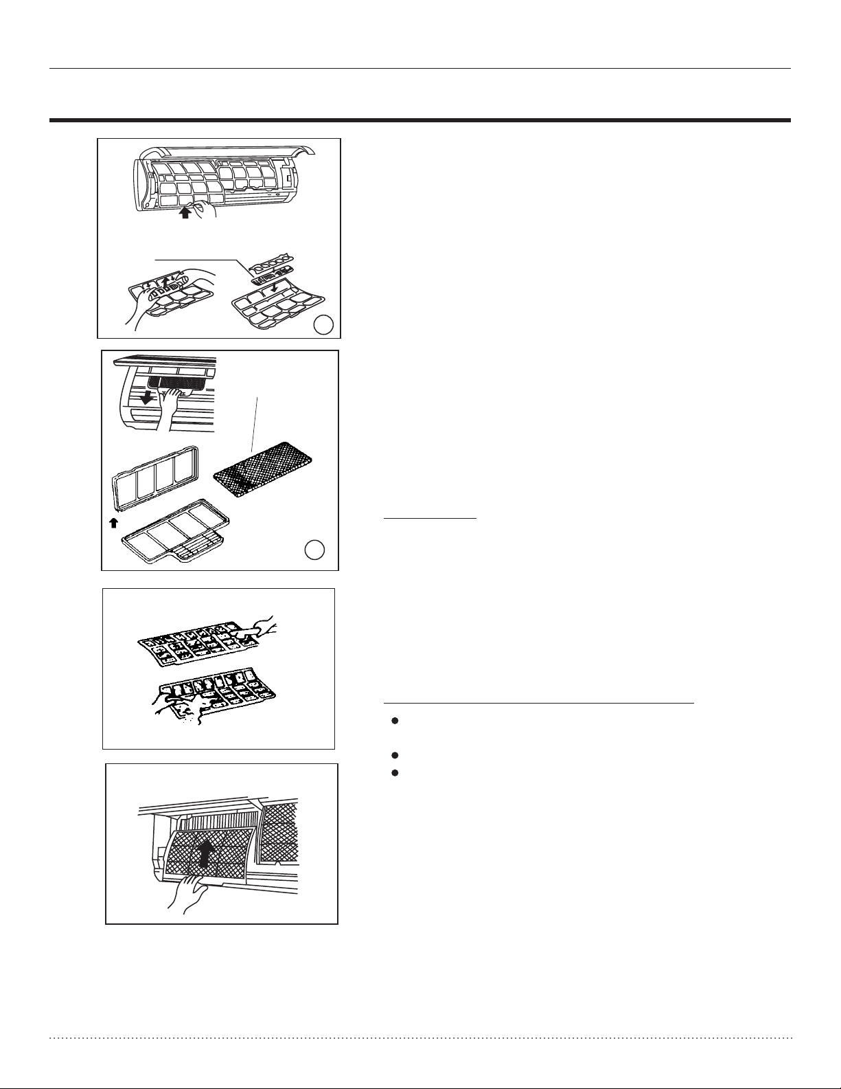
Cleaning the air filter
Filter Handle
Cleaning the air filter
Caution
Do not touch the metal parts of the unit when
removing the filter. Injuries can occur when
handling sharp metal edges.
Do not use water to clean inside the air conditioner.
Exposure to water can destroy the insulation,
leading to possible electric shock.
When cleaning the unit, first make sure that the
power and circuit breaker are turned off.
A clogged air filter reduces the cooling efficiency of
this unit. Please clean the filter once every 2 weeks.
1. Lift the indoor unit panel up to an angle until it
stops with a clicking sound.
2. Hold the handle of the air filter and lift it
up slightly to remove it from the filter holder,
then pull it downwards.
3. Remove the AIR FILTER from the indoor unit.
Once every two weeks,
clean the AIR FILTER
with a vacuum cleaner or water, then dry it
in cool place.
10
Page 11
Heat Controller, Inc. VMH 30/36 SERIES Owner’s Manual
The following events may occur during normal operation.
1. Protection features.
Compressor protection
The unit is programmed to protect the compressor by not letting it re-start for 3 minutes
after being stopped.
Anti-cold air (Cooling and heating models only)
The unit is designed not to blow cold air on HEAT mode, when the indoor heat exchanger is in
one of the following three situations and the set temperature has not been reached.
A) When heating has just starting.
B) Defrosting.
C) Low temperature heating.
Defrosting (Cooling and he
Frost may be generated on the outdoor unit during heat cycle when outdoor temperature is low
and humidity is high, resulting in lower heating efficiency of the air conditioner.
During this condition the air conditioner will stop heating operation and start defrosting automatically.
Defrost time may vary from 4 to 10 minutes according to the outdoor temperature and
the amount of frost build up on the outdoor unit.
2. A white mist coming out of the indoor unit
A white mist may generate due to a large temperature difference between air inlet and air outlet
on COO
A white mist may generate due to moisture generated from defrosting process when the air
conditioner restarts in HEAT mode operation after defrosting.
3. Typical sounds
You may hear a low hissing sound when the compressor is running or has just stopped running.
This sound is the sound of the refrigerant flowing or coming to a stop.
You can also hear a low "squeak" sound when the compressor is running or has just stopped
running. This is caused by heat expansion and cold contraction of the plastic parts in the unit
wh
en the temperature is changing.
A noise may be heard due to louver restoring to its original position when power is first turned on.
4. Dust is blown out from the indoor unit.
This is a normal condition when the air conditioner has not been used for a long time or during first
use of the unit, and an accumulation of dust has formed on the unit’s outlet. Cleaning dust off of the
unit before operation may prevent this.
5. A peculiar smell comes out of the indoor unit.
This is caused by the indoor unit giving off smells permeated from building material, from furniture,
or smoke. However, a burning sme
and call an authorized servicer if such smell exists.
6. Operating mode changes to fan only mode.
When indoor temperature reaches the temperature set point on air conditioner, the compressor will
stop automatically, and the air conditioner changes to FAN only mode. The compressor will start
again when the indoor temperature rises in above the set point in COOL mode or falls in below the
set point in HEAT mode.
The indoor or outdoor fan will stop running when defrosting.
CARE AND MAINTENANCE
CARE AND MAINTENANCE
Air freshening filter
Air freshening filter
4. Remove the Air Freshening Filter from its support
frame (on some models).
The removing and installation methods are slightly
different, see the pictures marked and on the left.
.
Clean the air freshening filter at least once a
month, and replace it every 4-5 months.
.
Clean it with vacuum cleaner, then dry it in cool
place.
5. Install the air freshening filter back into position.
6. Insert the upper portion of air filter back into the
1
2
unit, taking care that the left and right edges are
aligned correctly and place filter into position.
Maintenance
If you plan to store the unit for a long time, perform
the following:
(1) Operate the fan for about half a day to dry the
inside of the unit.
(2) Stop the air conditioner and disconnect power.
Remove the batteries from the remote controller.
(3) The outdoor unit requires periodic maintenance
and cleaning. Do not attempt to do this yourself.
Contact an authorized servicer.
Checks before placing back into operation
Check that the wiring is not broken off or
disconnected.
Check that the air filter is installed.
Check if the air outlet or inlet is blocked after the
air conditioner has not been used for a long time.
u v
11
Page 12

Owner’s Manual VMH 30/36 SERIES Heat Controller, Inc.
OPERATION TIPS
OPERATION TIPS
The following events may occur during normal operation.
1. Protection features.
Compressor protection
The unit is programmed to protect the compressor by not letting it re-start for 3 minutes
after being stopped.
Anti-cold air (Cooling and heating models only)
The unit is designed not to blow cold air on HEAT mode, when the indoor heat exchanger is in
one of the following three situations and the set temperature has not been reached.
A) When heating has just starting.
B) Defrosting.
C) Low temperature heating.
Defrosting (Cooling and heating models only
The indoor or outdoor fan will stop running when defrosting.
Frost may be generated on the outdoor unit during heat cycle when outdoor temperature is low
and humidity is high, resulting in lower heating efficiency of the air conditioner.
During this condition the air conditioner will stop heating operation and start defrosting automatically.
Defrost time may vary from 4 to 10 minutes according to the outdoor temperature and
the amount of frost build up on the outdoor unit.
2. A white mist coming out of the indoor unit
A white mist may generate due to a large temperature difference between air inlet and air outlet
on COOL mode in an indoor en
A white mist may generate due to moisture generated from defrosting process when the air
conditioner restarts in HEAT mode operation after defrosting.
vironment that has a high relative humidity.
)
3. Typical sounds
You may hear a low hissing sound when the compressor is running or has just stopped running.
This sound is the sound of the refrigerant flowing or coming to a stop.
You can also hear a low "squeak" sound when the compressor is running or has just stopped
running. This is caused by heat expansion and cold contraction of the plastic parts in the unit
when the temperatur
A noise may be heard due to louver restoring to its original position when power is first turned on.
4. Dust is blown out from the indoor unit.
This is a normal condition when the air conditioner has not been used for a long time or during first
use of the unit, and an accumulation of dust has formed on the unit’s outlet. Cleaning dust off of the
unit before operation may prevent this.
5. A peculiar smell comes out of the indoor unit.
This is caused by the indoor unit giving off smells permeated from building material, from furniture,
or smoke. However, a burning smell may mean somethi
and call an authorized servicer if such smell exists.
6. Operating mode changes to fan only mode.
When indoor temperature reaches the temperature set point on air conditioner, the compressor will
stop automatically, and the air conditioner changes to FAN only mode. The compressor will start
again when the indoor temperature rises in above the set point in COOL mode or falls in below the
set point in HEAT mode.
e is changing.
ng is wrong with the unit. Power off the unit
12
Page 13

Heat Controller, Inc. VMH 30/36 SERIES Owner’s Manual
Troubleshooting Tips
Notes: Do not attempt to repair the unit yourself.
OPERATION TIPS
Stop the air conditioner immediately if one of the following errors occur. Disconnect the
power and contact the nearest authorized servicer.
Trouble
Malfunctions
Unit does not
start or operate
at all
Fan is operating
but unit is
poorly cooling
or heating
If the problems persist after performing these checks, or if you notice burning smells, or the
problem can’t be resolved by disconnecting and reconnecting power, then immediately stop
operating the unit and disconnect the power. Then call an authorized servicer.
OPERATION TIPS
Condensation
7. Dripping water may generate on the surface of the indoor unit when cooling in a relativley high
humidity (higher than 80%). Adjust the horizontal louver to the maximum air outlet position and
select HIGH fan speed to avoid this.
8. Heating mode
The air conditioner draws in heat from the outdoor unit and releases it via the indoor unit
during heating operation. When the outdoor temperature falls, heat drawn in by the air
conditioner decreases accordingly. At the same time, the heat load of the air conditioner
increases due to a larger difference between indoor and outdoor temp
comfortable temperature can't be achieved by the air conditioner, we suggest you use a
supplementary heating device.
9. Auto-restart function
Power failure during operation will stop the unit completely.
For the unit without Auto-restart feature, when the power restores, the OPERATION indicator
on the indoor unit starts flashing. To restart the operation, push the ON/OFF button on the
remote controller.
For the unit with Auto-restart feature, when the power restores, the unit restarts automatically with
all the previous settings p
automatically to a pre-programmed position.
eratures. If a
reserved by the memory function. For some models, the louver will open
Electrical Interference
10.
Electronic equipment which was radio transmitters may interfere with the units signals and cause it
to malfunction, if in close proximity. If this occurs, d
the unit with power again. Push the ON/OFF button on the remote controller to restart operation.
Ensure the unit is far away from and electrical interface sources to prevent this.
isconnect the unit with power and then re-connect
13
Page 14

Owner’s Manual VMH 30/36 SERIES Heat Controller, Inc.
TROUBLESHOOTING TIPS
Troubleshooting Tips
TROUBLESHOOTING TIPS
Stop the air conditioner immediately if one of the following errors occur. Disconnect the
power and contact the nearest authorized servicer.
If the following error codes appear on the LED display, disconnect the power and contact
an authorized servicer: E0,E1,E2,E3,E4,E5,E6,E7,E8 or P0,P1,P2,P3,P4,P5, P6.
Trouble
Malfunctions
Unit does not
start or operate
at all
Fan is operating
but unit is
poorly cooling
or heating
Fuse blows or circuit breaker trips frequently.
Indicator or lights flash rapidly and can not be
disconnecting the power and then connecting it in again.
Cause
Power to the unit may be interrupted.
Fuse may have blown out or circuit
breaker has tripped.
Batteries in Remote controller may
be dead or installed correctly.
Is the unit’s times set incorrectly?.
Temperature setting may be set
inappropriately.
A filter may be blocked.
stopped by
What should be done?
Wait for the power to be restored, call
your local utility distributor or an
electrician to address power supply issues.
Replace the fuse or flip the circuit
breaker back on.
Replace the batteries and ensure
the polarities are correct.
Wait or cancel timer setting.
Set temperature correctly.
Clean the air filter to prevent air
flow blockages.
Doors or Windows are open inside
the room you are to attempting to
heat or cool.
Air inlet or outlet of indoor or outdoor
unit is blocked.
Compressor will not restart.
If the problems persist after performing these checks, or if you notice burning smells, or the
problem can’t be resolved by disconnecting and reconnecting power, then immediately stop
operating the unit and disconnect the power. Then call an authorized servicer.
Notes: Do not attempt to repair the unit yourself.
Always consult an authorised service provider.
14
Close the doors and windows, within
the area to be cooled or heated to
increase efficiency and performance.
Clear obstructions away first, then
restart the unit.
Wait approximately 3 minutes for the
compressor to turn on to begin
heating/cooling.
Page 15
Heat Controller, Inc. VMH 30/36 SERIES Owner’s Manual
12/14/11
15
 Loading...