

Page 1
INSTALLATION
MANUAL
VMH 09/12/18/27/36
Version C
InverterFlex
Ductless Mini-Split Heat Pump
Heat Controller, Inc. • 1900 Wellworth Ave. • Jackson, MI 49203 • (517)787-2100 • www.heatcontroller.com
Page 2

VMH InverterFlex Mini-Split INSTALLATION MANUAL Heat Controller, Inc.
Table of Contents
Safety Precautions
Warnings and Cautions ...........................................................................2
Installation Instructions
Selecting an installation location ..............................................................3
Accessories..............................................................................................4
System installation ...................................................................................5
Indoor unit installation ..............................................................................6
Outdoor unit installation ........................................................................... 9
Refrigerant Pipe Connection
Refrigerant pipe connection ...................................................................10
Electrical Work
Electrical Work .......................................................................................12
Air Purging
Air purging with vacuum pump...............................................................14
Safety and refrigerant leak check ..........................................................16
Testing the System
Test Run .................................................................................................17
!
Caution
• Contact an authorized service technician for repair or maintenance of this unit.
• Contact an authorized installer for installation of this unit.
• Installation work must be performed in accordance with local and national electrical
codes and standards by authorized personnel only.
1
Page 3
Heat Controller, Inc. INSTALLATION MANUAL VMH InverterFlex Mini-Split
• Read the follow SAFETY PRECAUTIONS carefully before installation.
• Electrical work must be performed by a licensed electrician. Be sure to use the correct rating of the power
cord and main circuit for the model to be installed.
• Incorrect installation due to ignoring the instruction will cause harm or damage.
n The seriousness is classied by the following indications.
WARNING!
!
CAUTION!
!
The items to be followed are classied by the symbols:
This symbol indicates the possibility of death or serious injury.
This symbol indicates the possibility of injury or damage to property.
This symbol denotes item that is PROHIBITED from doing.
WARNING!
!
1) Do not install without an authorized servicer/installer.
2) Install according to this installation instruction. If installation is defective, it can cause water leakage, or
electrical shock/re.
3) Use the supplied accessories and specied parts for installation.
4) Install the indoor unit on a wall strong enough to hold the unit’s weight. Install the outdoor unit on a
raised concrete pad or blocks to provide a solid, level foundation. In a location with high winds, anchor
the unit and provide an air bafe. In snowy areas (for heat pump models), install the outdoor unit on a
raised platform so that it is higher than drifting snow. Provide snow vents.
5) For electrical work, follow local and national electric codes and these installation instructions. An
independent circuit and single outlet must be used. If electrical circuit capacity is not enough or defects
are found in electrical work, it will cause electrical shock or re.
6) Use the specied cable and connect tightly and clamp the cable so that no external force will stress the
terminal. Loose wiring may cause overheating at the connection points and a possible re hazard.
7) Wiring routing must be properly arranged so that control board cover is xed properly. If control board
cover is not xed perfectly, it will cause overheating at connection point of terminal, re or electrical shock.
8) When charging the unit, take care not to let air/substances other than the specied refrigerant go into
refrigeration cycle. Otherwise, it will cause lower capacity, abnormal high pressure in the refrigeration
cycle, explosion and injury.
9) Do not modify the length of the power supply cord or use an extension cord, and do not share the
single outlet with other electrical appliances. Otherwise, it will cause re or electrical shock.
CAUTION!
!
1) This equipment must be grounded and installed with a ground leakage current breaker. It may cause
electrical shock if grounding work doesn’t comply with local/national electric codes.
2) Do not install the unit at place where leakage of ammable gas may occur. If gas leaks and
accumulates near the unit, it may cause re.
3) Carry out drainage piping as mentioned in installation instructions. If not done correctly, water may
enter the room and damage personal belongings.
2
Page 4
VMH InverterFlex Mini-Split INSTALLATION MANUAL Heat Controller, Inc.
1. Wall-mounted type
Selecting installation place
Read completely, then follow step by step.
Indoor unit
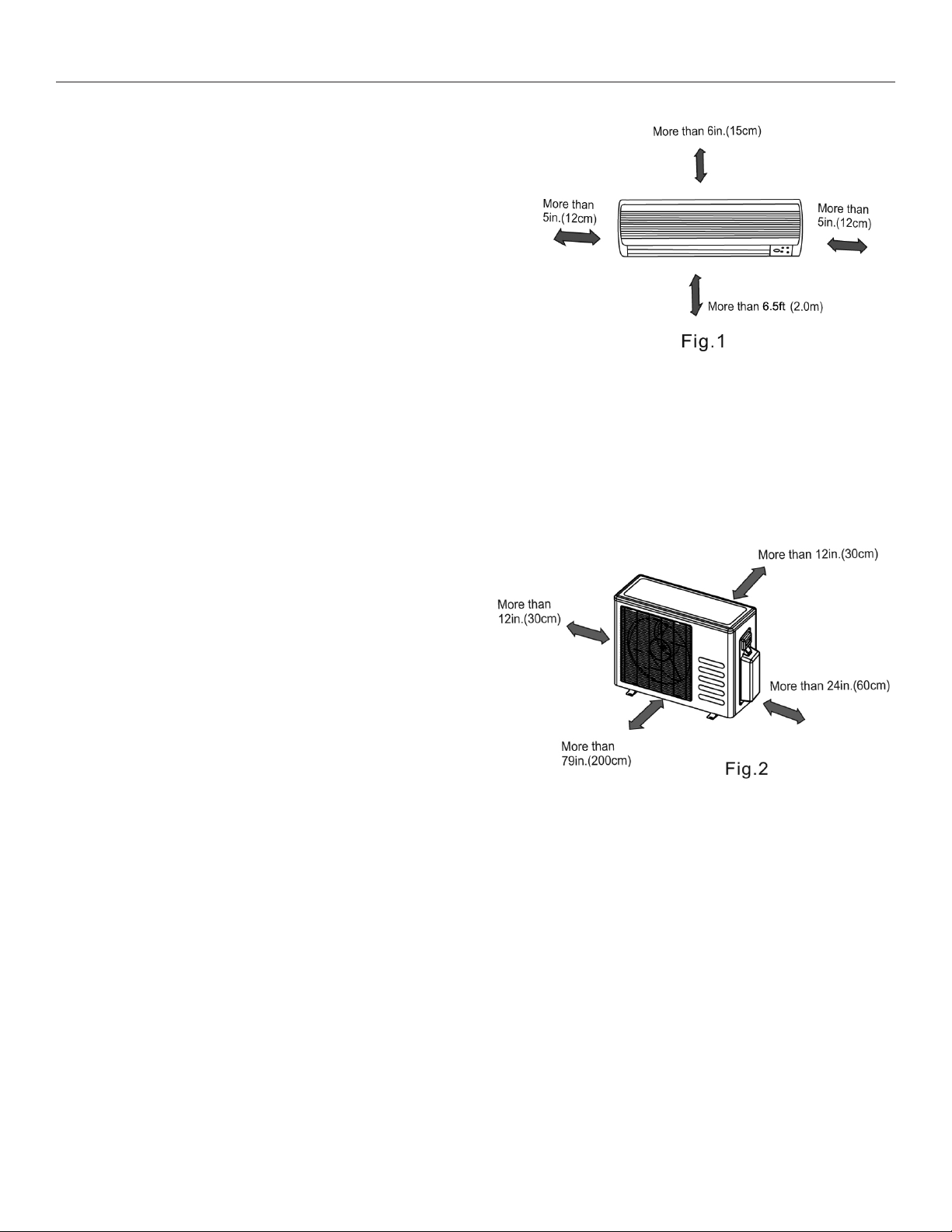
• Do not expose the indoor unit to heat or steam.
• Select a place where there are no obstacles in front or
around the unit.
• Make sure that condensation drainage can be conveniently
routed away.
• Do not install near a doorway.
• Ensure that the space on the left and right of the unit is more than 5in.(12cm).
• Use a stud nder to locate studs to prevent unnecessary damage to the wall.
• The indoor unit should be installed on the wall at a height of 6.5ft.(2m) or more from the oor.
• The indoor unit should be installed allowing a minimum clearance of 6in.(15cm) from the ceiling.
• Any variations in pipe length may require adjustment to refrigerant charge.
• Do not expose unit to direct sunlight. The sun will fade the plastic cabinet and affect its appearance.
Outdoor unit
• If an awning is built over the outdoor unit to prevent
direct sunlight or rain exposure, make sure that heat
radiation from the condenser is not restricted.
• Ensure that the clearance around the back of the unit
is more than 12in.(30cm) and left side is more than
12in.(30cm). The front of the unit should have more
than 79in.(200cm) of clearance and the connection
side (right side) should have more than 24in.(60cm)of
clearance.
• Do not place animals and plants in the path of the air
inlet or outlet.
• Take the air conditioner weight into account and select a place where noise and vibration will not be an issue.
• Select a place so that the warm air and noise from the air conditioner do not disturb neighbors.
Rooftop installation
• If the outdoor unit is installed on a roof structure, be sure to level the unit.
• Ensure the roof structure and anchoring method are adequate for the unit location.
• Consult local codes regarding rooftop mounting.
• If the outdoor unit is installed on roof structures or external walls, this may result in excessive noise and vibration, and may also be considered a non-serviceable installation.
3
Page 5
Heat Controller, Inc. INSTALLATION MANUAL VMH InverterFlex Mini-Split
INSTALLATION INSTRUCTIONS
Tool s nee ded for ins tal lation:
Level gauge
Level gaug e
Screwdriver
Screwdriv er
Electric d rill,Hole core drill ( 26in.(65mm))
Electric drill, Hole core drill (o .25in.(65mm))
Flaring to ol set
Flaring tool set
Specified torque wrenches: 1.8kgf.m, 4.2kgf.m,
Torque wrench
5.5kgf.m, 6.6kgf.m(dif ferent depending on mod el No.)
Spanner (half union)
Spanner (h alf union)
Hexagonal wrench (1.5in.(4mm))
Hexagonal wrench (1.5in.(4mm))
Gas-leak detector
Gas-leak d etector
Vacuum pump
Gauge mani fold
Users manu al
Thermomet er
Multimete r
Pipe cutte r
Measuring tape
Accessories
Qty/unit
Number
Name of Accessories
Q ty/one unit
1
2
3
4
5
6
7
8
9
Note: Except the above parts provided, the other parts needed during installation y ou must
purchase.
4
Installation Plate
Plastic Expansio n Sheath
Self-tapping Screw A ST3.9X25
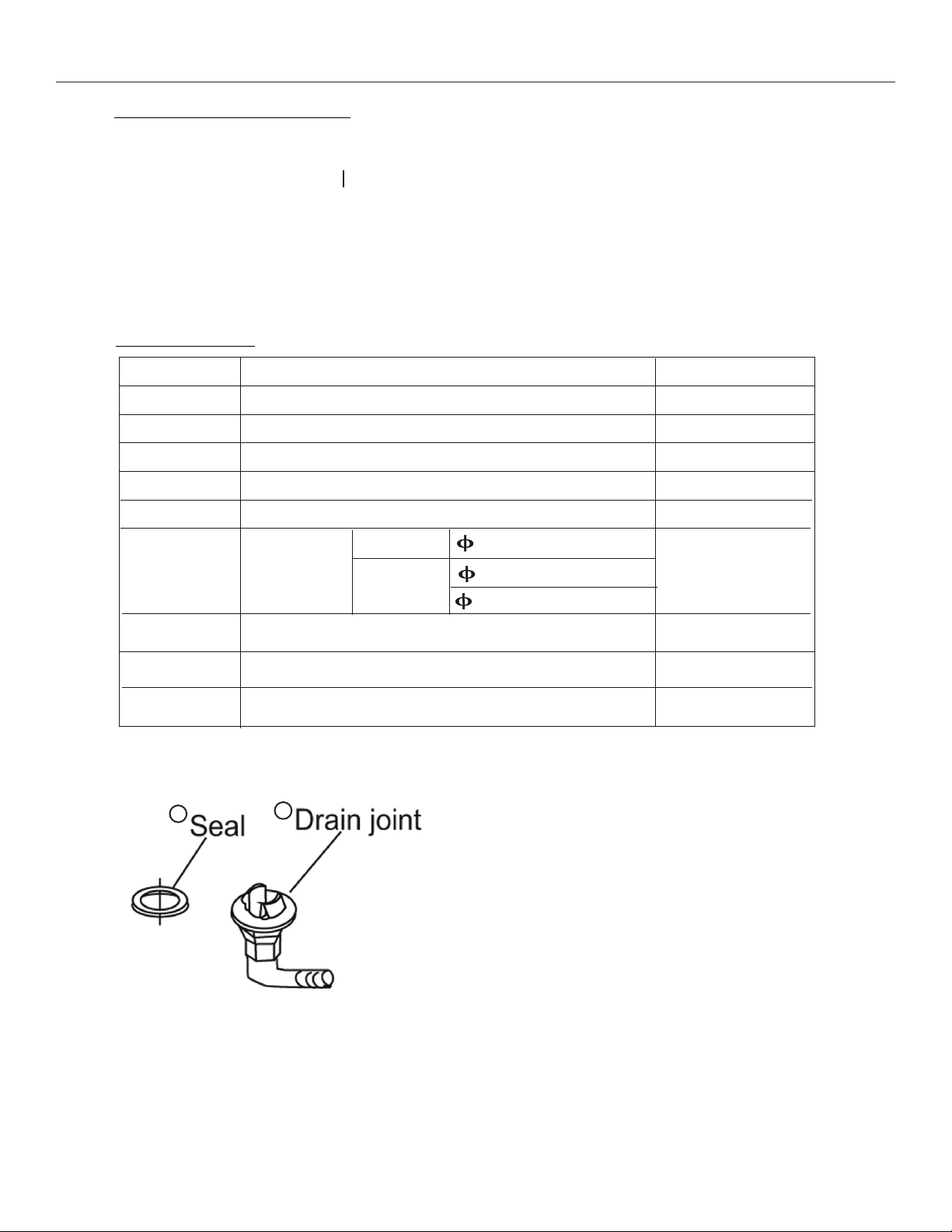
Seal (See Page 8 for details)
Drain Joint
Connecting
(See page 8 for details)
Liquid side
pipe
Assembly
Gas side
Remote controller
Self-tapping Screw B ST2.9X10
Remote controller holder
5
1/4" (6.35mm)
6.35
( 12000Bt u/ h mode l)
3/8" (9.53mm) (<12,000 Btu/h model)
9.53
1/2" (12.7mm) (≥12,000 Btu/h model)
( 12000Bt u/ h mode l)
12.7
1
8
8
1
1
Parts you must
purchase
(The minimum pipe
wall-thickness
of 0.7mm is required. )
1
2
1
4
Page 6
VMH InverterFlex Mini-Split INSTALLATION MANUAL Heat Controller, Inc.
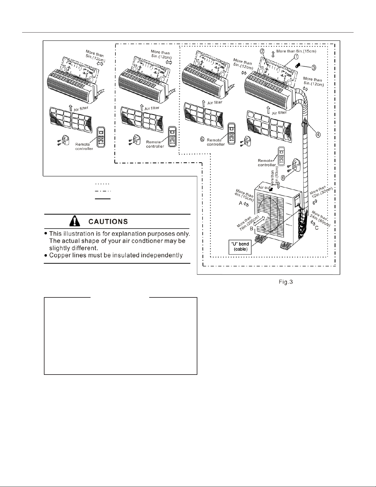
Single-Dual Zone
Single-Tri Zone
Single-Quad Zone
CAUTION
• Use a stud nder to locate studs to prevent
unnecessary damage to the wall.
• A minimum pipe run of 9.8 ft (3m) is required to minimize vibration & excessive
noise.
• Two of the “A,” “B” and “C” air ow directions should be free from obstructions for
the outdoor unit.
5
Page 7

Heat Controller, Inc. INSTALLATION MANUAL VMH InverterFlex Mini-Split
Indoor unit installation (wall-mounted type)
1. Installation Plate
A. Mount the installation plate horizontally on struc-
tural parts (studs) of the wall with proper clear-
ance around the installation plate.
B. If the wall is made of brick, concrete or the like,
drill eight (8) 5mm (0.2in.) diameter holes in
the wall.Insert anchor for appropriate mounting
screws.
C. Fit the installation plate on the wall with eight (8)
type “A” screws.
NOTE:
Fit the Installation Plate and drill holes in the wall according to the wall structure and corresponding mounting points on the installation plate. The Installation
Plate may be slightly different according to the different
models of indoor unit.
Model A in. (mm) B in. (mm)
28 (710) 10 (250)
<12,000 Btu/h
≥12,000 Btu/h
30 (750) 10 (250)
31 (780) 11 (270)
32 (790) 10 (265)
31 (780) 11 (270)
32 (815) 11 (280)
2. Drill a hole in the wall
A. Determine hole positions according to the dia-
gram detailed in Fig.5. Drill one (1) hole ( 3in.
(65mm)) slanting slightly toward the outdoors,
as shown in Fig. 6.
B. Always use wall hole conduit when drilling metal
grid, metal plate or the like.
3. Connective Pipe and Drainage Installation
A. Run the drain hose sloping downward. Do not
install the drain hose as illustrated in Fig.7.
6
Page 8

VMH InverterFlex Mini-Split INSTALLATION MANUAL Heat Controller, Inc.
INSTALLATION INSTRUCTIONS
2. When connecting extension drain hose,
insulate the connecting part of extension
drain hose with a shield pipe, do not let
the drain hose slack.
Wall Cap
Connective pipe installation
1. For the left-hand and right-hand piping,
remove the pipe cover from the side
panel.
2. For the rear-right-hand and rear-left-hand
piping, install the piping as shown in Fig.9.
Bend the connective pipe to be laid at 4in.(43mm)
height or less from the wall.
3. Fix the end of the connective pipe. (Refer
to Tightening Connection in REFRIGERANT
PIPING CONNECTION)
Fig.8
Right-hand piping
Left-hand piping
Rear-right piping
Rear-left piping
4. Piping and wrapping
Bundle the tubing, connecting cable, and drain
hose with tape securely, evenly as shown in
Fig.11.
Because the condensed water from rear of the
indoor unit is gathered in ponding box and is
piped out of room. Do not put anything else in
the box.
CAUTION
Connect th e indoor unit f irst, then the
• Connect the indoor unit rst, then the outdoor
outdoor un it.
unit.
Do not allo w the piping to let out from
• Do not allow the piping to let out from the back
the back of the indoor unit.
of the indoor unit.
Be careful not to let the d rain hose slack.
• Be careful not to let the drain hose slack.
Heat insul ated both of the auxiliary piping.
• Heat insulate both of the auxiliary piping.
Be sure tha t the drain hose is lo cated at
the lowest side of the bundle. L ocating
• Be sure that the drain hose is located at the low-
at the uppe r side can cause d rain pan
est side of the bundle. Locating at the upper side
to overflo w inside the unit.
can cause drain pan to overow inside the unit.
Never intercross nor intertwist the power
• Never intercross nor intertwine the power wire
wire with a ny other wiring.
with any other wiring.
Run the dra in hose sloped downward to
• Run the drain hose sloped downward to drain
drain out t he condensed water smoothly .
out the condensed water smoothly.
Indoor unit outline
.
.
.
.
.
.
.
.
.
.
.
.
.
.
.
.
.
.
.
.
.
.
.
.
.
.
.
.
.
.
.
.
.
Drain hose
.
.
.
Indoor unit
.
Connective
cable
Fig.9
Connective pipe
43
.
.
.
.
.
.
.
.
.
.
.
.
.
.
.
.
.
.
.
.
.
.
.
.
.
.
.
.
.
.
.
.
.
.
.
.
.
.
.
.
.
.
.
.
.
.
Fig.10
Fig.11
.
.
.
.
.
.
.
.
.
.
.
.
.
.
.
.
.
.
.
.
.
.
.
.
.
.
.
.
.
.
.
.
.
.
.
.
.
.
.
.
.
.
.
.
.
.
.
.
.
.
.
.
.
.
Ponding box
Pipe room
Connective
pipe
Wrapping belt
.
.
.
.
.
.
.
.
.
.
.
.
.
.
.
.
.
.
.
7
Page 9

Heat Controller, Inc. INSTALLATION MANUAL VMH InverterFlex Mini-Split
4. Indoor unit installation
1. Pass the piping through the hole in the wall.
2. Put the upper claw at the back of the indoor
unit on the upper hook of the installation
plate, move the indoor unit from side to
side to see that it is securely fastened (see
Fig.12).
3. Separate the bottom of the indoor unit from
the wall by inserting spacer, etc., between
the indoor unit and the wall. Remove spacer
after piping is complete.
4. Push the lower part of the indoor unit up on
the wall, then move the indoor unit from side
to side, up and down to check if it is secure.
Spacer
8
Page 10

VMH InverterFlex Mini-Split INSTALLATION MANUAL Heat Controller, Inc.
Outdoor Unit Installation
Outdoor installation precaution
• Install the outdoor unit on a rigid base to prevent
increasing noise level and vibration.
• Determine the air outlet direction where the
discharged air is not blocked. If the installation
place is exposed to strong winds, ensure the unit
is lengthwise along the wall or provide a suitable
air bafe.
• If suspending the unit, follow the bracket manu-
facturer’s instructions.
• Use a raised concrete pad or concrete blocks to
provide a solid, level surface. Securely anchor the
unit down with bolts.
• Be sure there are no obstacles which block radiat-
ing air.
• In a snowy area, install the outdoor unit on a raised
platform that is higher than drifting snow.
Anchoring outdoor unit
Anchor the outdoor unit with 5/16" (8mm) or 3/8"
(10mm) bolt and nut tightly and horizontally on a
concrete or rigid mount.
Outdoor unit dimensions
WxHxD in. (mm)
29.9 x 23.2 x 11.2 (760 x 590 x 285) 20.9 (530) 11.4 (290)
33.3 x 27.4 x 13.2 (845 x 695 x 335) 22 (560) 13.2 (335)
35.2 x 33.9 x 13.0 (895 x 860 x 330) 23.2 (590) 13.1 (333)
39.0 x 38.0 x 14.0 (990 x 965 x 355) 24.5 (623) 14.4 (366)
Mounting Dimensions
A in. (mm) B in. (mm)
Fig. 45
9
Page 11

Heat Controller, Inc. INSTALLATION MANUAL VMH InverterFlex Mini-Split
REFRIGERANT PIPE CONNECTION
Drain joint installation
Fit the seal into the drain elbow, then insert the
drain joint into the base pan hole of outdoor unit,
rotate 90 to securely assemble them.
Connecting the drain joint with an extension drain
hose (locally purchased) is recommended.
hose (Locally purchased), in case of the water
draining off the outdoor unit during the heating
mode.
Seal
Drain joint
Fig.46
Base pan hole of
outdoor unit
Seal
Drain pipe
Refrigerant pipe connection
1. Flaring work
Main cause for refrigerant leakage
is due to defect in the flaring work.
Carry out correct flaring work
using the following procedure:
A: Cut the pipes and the cable.
Use line set kit or copper tubes/pipes
1. Use the piping kit accessory or pipes
purchased locally.
purchased locally.
2. Measure the distance between the indoor
and the outdoor unit.
3. Cut the pipes a little longer than the
Cut the pipes/tubes a little longer than
measured distance.
the measured distance.
4. Cut the cable 1.5m longer than the pipe
Cut the cable 1.5m longer than the pipe/
length.
tube length.
90
Point down
Oblique
Fig.47
Pipe
Reamer
Roughness
Burr
B: Burr removal
1. Complet ely remove all burrs from the c ut
cross sect ion of pipe/tube.
2. Put the end of the copper tube/pipe in a
downward d irection as you remove burr s in
order to avoid dropping burrs into the tu bing.
C: Putting nut on
Remove fla re nuts attached to indoor and
outdoor un it, then put them on pipe/tube
having com pleted burr removal.(not possible
to put them on after flaring work)
Fig.48
Flare nut
Copper tube
Fig.49
10
Page 12

VMH InverterFlex Mini-Split INSTALLATION MANUAL Heat Controller, Inc.
Refrigerant Pipe Connection
D: Flaring work
Firmly hold copper pipe in a die in the dimension shown
in the table below.
Outer diameter
in. (mm)
o 1/4" (6.35) 0.5 (1.3) 0.276 (0.7)
o 3/8" (9.35) 0.63 (1.6) 0.394 (1.0)
o 1/2" (12.7) 0.709 (1.8) 0.394 (1.0)
Max. Min.
A in. (mm)
Tightening Connection
• Align the center of the pipes.
• Sufciently tighten the are nut with ngers, and then
tighten it with a spanner and torque wrench as shown
in Fig.51 & 52.
Outer
Diameter
o 1/4" (6.35)
o 3/8" (9.35)
o 1/2" (12.7)
Tightening
torque
11.57 ft-lb
(160 kgf-cm)
21.69 ft-lb
(300 kgf-cm)
36.17 ft-lb
(500 kgf-cm)
Additional tightening
torque
14.46 ft-lb
(200 kgf-cm)
25.3 ft-lb
(350 kgf-cm)
39.78 ft-lb
(550 kgf-cm)
Caution
Excessive torque can break nut depending on
installation conditions.
11
Page 13

Heat Controller, Inc. INSTALLATION MANUAL VMH InverterFlex Mini-Split
Electrical Work
Electric safety regulations for the initial Installation
1. Power voltage should be in the range of 90%~110%of rated voltage.
2. The creepage protector and main power switch with a 1.5 times capacity of Max. Current of the unit should
be installed in power circuit.
3. Ensure the air conditioner is grounded well.
4. Connect wiring to the unit according to the electrical diagram located on the panel of the outdoor unit.
5. All wiring must comply with local and national electrical codes and be installed by qualied and skilled
electricians.
6. An individual branch circuit and single receptacle used only for this air conditioner must be available.
CAUTION
1) Never fail to have an individual power circuit specically for the air conditioner.
As for the method of wiring, be guided by the circuit diagram posted on the inside of control cover.
2) The screws which fasten the wiring in the casing of electrical ttings are liable
to come loose from vibrations to which the unit is subjected during the course
of transportation. Check them and make sure that they are all tightly fastened. (If
they are loose, it could cause burn-out of the wires.)
3) Specication of power source.
4) Conrm that electrical capacity is sufcient.
5) See that the starting voltage is maintained at more than 90 percent of the rated
voltage marked on the name plate.
6) Conrm that the cable thickness is as specied in the power source specication.
7) Always install an earth leakage circuit breaker in a wet or moist area.
8) The following would be caused by voltage drop.
Vibration of a magnetic switch, which will damage the contact point, fuse breaking,
disturbance of the normal function of the overload.
9) The means for disconnection from a power supply shall be incorporated in the
xed wiring and have an air gap contact separation of at least 3mm in each
active(phase) conductors.
12
Page 14

VMH InverterFlex Mini-Split INSTALLATION MANUAL Heat Controller, Inc.
Electrical Work
• Do not touch the capacitor even if you have
disconnected the power or electric shock haz-
ard may occur. For your safety, you should start
repairing at least 5 minutes after the power is
disconnected.
• The power is supplied from the Outdoor Unit.
Up to four indoor units are connected with signal
wires or power cords.
Connect the cable to the outdoor unit
1. Remove the electrical control board cover from
the outdoor unit by loosening the screw as
shown in Fig.53.
2. Connect the connective cables to the terminals
as identied with their respective matched numbers on the terminal block of indoor and outdoor
units.
3. Secure the cable onto the control board with the
cord clamp.
4. To prevent rain water from running along the
connective cable to the inside of the buiding/
room where the unit is located, make a “U” bend
trap.
5. Insulate unused cords (conductors) with PVC-
tape. Ensure that they do not touch any electrical
or metal parts.
13
Page 15

Heat Controller, Inc. INSTALLATION MANUAL VMH InverterFlex Mini-Split
Air Purging
Air and moisture in the refrigerant system have undesirable effects as indicated below:
• Pressure in the system rises.
• Operating current rises.
• Cooling or heating efciency drops.
• Moisture in the refrigerant circuit may freeze and block capillary tubing.
• Water may lead to corrosion of parts in the refrigeration system.
Therefore, the indoor unit and tubing between the indoor and outdoor unit must be leak tested and evacuated
to remove any noncondensables and moisture from the system.
Air purging with vacuum pump
Preparation
• Check that each tube(both liquid and gas side tubes) between the indoor and outdoor units have
been properly connected and all wiring for the test run has been completed. Remove the service
valve caps from both the gas and the liquid side on the outdoor unit. Note that both the liquid and the
gas side service valves on the outdoor unit are kept closed at this stage.
• Pipe length and refrigerant amount:
Connective Pipe Length Air Purging Method Additional amount of refrigerant to be charged
Less than 16.5 ft. (5m) Use vacuum pump ———————
More than 16.5 ft. (5m) Use vacuum pump (Pipe length-5m) 15g/m
(Pipe length-16.5 ft.) x 5 oz/ft.
14
Page 16

VMH InverterFlex Mini-Split INSTALLATION MANUAL Heat Controller, Inc.
Air Purging
• When relocating the unit to another place, perform evacuation
using vacuum pump.
• Make sure the refrigerant added into the air conditioner is liquid
form.
Caution in handling the packed valve
• Open the valve stem until it hits against the stop. Do not try to
open it further.
• Securely tighten the valve stem cap with a spanner or the like.
• Valve stem cap tightening torque (see tightening torque table).
When Using the Vacuum Pump
(For method of using a manifold valve, refer to its operation
manual.)
1. Completely tighten the are nuts, A, B, C, D, connect the manifold valve charge hose to a charge port of the low-pressure
valve on the gas pipe side.
2. Connect the charge hose connection to the vacuum pump.
3. Fully open the Lo handle of the manifold valve.
4. Operate the vacuum pump to evacuate. After starting evacua-
tion, slightly loose theare nut of the Lo valve on the gas pipe
side and check that the air is entering(Operation noise of the
vacuum pump changes and a compound meter indicates 0
instead of minus)
5. After the evacuation is complete, fully close the Lo handle
of the manifold valve and stop the operation of the vacuum
pump. Evacuate for 15 minutes or more and check that the
compound meter indicates -29.92 inHg (-1x10⁵Pa).
6. Turn the stem of the packed valve B about 45° counterclockwise for 6~7 seconds after the gas comes out, then tighten the
are nut again. Make sure the pressure display in the pressure
indicator is a little higher than the atmosphere pressure.
7. Remove the charge hose from the Low pressure charge hose.
8. Fully open the packed valve stems B and A.
9. Securely tighten the cap of the packed valve.
-29.92 inHg
Lo Handle
Hi Handle
15
Page 17

Heat Controller, Inc. INSTALLATION MANUAL VMH InverterFlex Mini-Split
AIR PURGING
Air Purging
Safety and Leak Check
Safety and leakage check
E lectrical saf ety check
Perform the electric safe check after
completing installation:
1. Insulated resistance
The insulated resistance must be more than
2M .
2. Grounding work
After finishing grounding work, measure the
grounding resistance by visual detection and
grounding resistance tester. Make sure the
grounding resistance is less than 4 .
3. Electrical leakage check (performing during
test run).
test running)
During test operation after finishing installation,
the serviceman can use the electroprobe and
multimeter to perform the electrical leakage
check. Turn off the unit immediately if leakage
happens. Check and find out the solution
ways till the unit operate properly.
Indoor unit
check point
Outdoor unit
check point
C
a,b,c,d,h,i ,j , k are points for one -t wo type.
a,b,c,d,e,f ,, h, i,j,k,m,n ar e p oi nts for one- th re e type.
Fig.63
m
n
k
j
i
h
f
A
e
d
B
c
b
a
Refrigerant Leak Check
G as leak check
1. Soap wate r method:
Apply a soap water or a liquid neutral
Apply a soap wat er or a liquid neutral
detergent on the indoor unit connecti on
detergent on the indoor unit connection
or outdoor unit connections by a soft
or outdoor unit connections with a soft
brush to check for leaka ge of the
brush to check for leakage of the
connectin g points of th piping. If bubbles
connecting points of th piping. If bubbles
come out, the pipes have leakage.
come out, the pipes have leakage.
2.
Leak detec tor
Use the leak d etector to check for leakag e.
CAUTION
A: Lo packed valve B: Hi packed valve
C and D are ends of indoor unit connection.
NOTE: The illustration is for explanation
NOTE: The illustration is for explanation
purposes only. The actual order of A, B, C
purpose only. The actual order of A, B, C
and D on the machine may be slightly
and D on the machine may be slightly
different from the unit you purchased. The
different from the unit you purchased. The
actual shape shall prevail.
actual shape shall prevail.
Outdoor unit
check point
Indoor unit
check point
One-four typ e
Fig.64
16
Page 18

VMH InverterFlex Mini-Split INSTALLATION MANUAL Heat Controller, Inc.
Test running
TEST RUNNING
Testing the System
Perform test operation after completing gas lea k check at the flare nut connections an d
electrical safety ch eck.
Check that all tubing an d wiring have been properly connect ed.
Check that the gas and liquid side service valves are fully open.
1. Connect the power, pr ess the ON/OFF button on the re mote controller to turn the un it on.
2. Use the MODE button to select COOL, HEAT, AUTO and FAN to check if all the functions work
2. Use the MODE button to se lect COO L, HEAT, AU TO and FAN to che ck if all the functions
well.
works well.
3. When the ambient temperature is too low(lower than 62.2°F (17°C)), the unit cannot be controlled
3. When the amient tempe rature i s too low(lower tha n 17 C), the unit cannot be cont rolled by
by the remote controller to run in cooling mode, manual operation can be used. Manual opera-
the remote controller to run at cooling mode, manua l operat ion can be taken. Ma nual
tion is used only when the remote controller is disable or maintenance necessary.
operation is used only when the remote controller is disable or maintenance necessary.
Hold the panel sides and lift the panel up to an angle unti l it remains fixed with a click ing
sound.
Press the Manual control button to select the AUTO or COOL, the unit wi ll opera te under
Forced AUTO or COOL mode(see User Manual for details).
4. The tes t operation should last about 30 minutes.
Manual control
Button
Fig.65
Manual control
button
AUTO/COOL
17
Page 19

09/2010
 Loading...