

Page 1
OWNER’S MANUAL
VMH 09/12/18/27/36 InverterFlex
Version C
Single, Dual, Tri or Quad Zone
Ductless Mini-Split System
B-VCH12FC-1 and B-VCH18FC-1
Version C
Ceiling Cassette
Heat Controller, Inc. • 1900 Wellworth Ave. • Jackson, MI 49203 • (517)787-2100 • www.heatcontroller.com
Page 2

VMH InverterFlex Mini-Split OWNER’S MANUAL Heat Controller, Inc.
Table of Contents
Safety Precautions
Warning ...................................................................................................2
Caution ....................................................................................................2
Operating Instructions
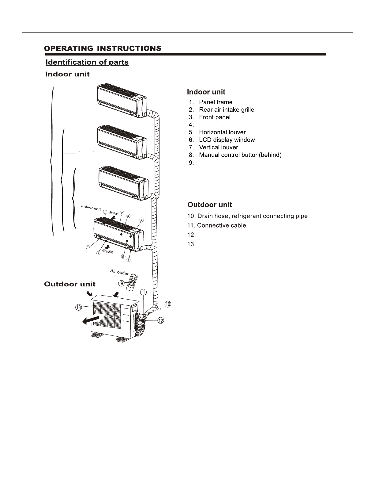
Identication of Parts ...............................................................................3
Display and Remote Controller Features ..............................................4-5
Operating Conditions and Manual Operation...........................................6
Airow Direction Control ..........................................................................7
Operation Modes .....................................................................................8
Care and Maintenance
Care and Maintenance...........................................................................10
Operation Tips
Typical Operational Occurrences ...........................................................12
Troubleshooting Tips
Troubleshooting Tips ..............................................................................14
Caution
!
• Contact an authorized service technician for repair or maintenance of this unit.
• Contact the installer for installation of this unit.
• Installation work must be performed in accordance with local and national electrical
codes and standards by authorized personnel only.
1
Page 3
Heat Controller, Inc. OWNER’S MANUAL VMH InverterFlex Mini-Split
To prevent injury to the user, other people and/or to property, the following instructions must be followed. Incorrect operation
due to ignoring these instructions may cause harm or damage. The seriousness is classied by the following indications:
WARNING!
!
CAUTION!
!
Meanings of symbols used in this manual are as shown below:
This symbol indicates the possibility of death or serious injury.
This symbol indicates the possibility of injury or damage to property.
Never do this.
!
WARNING!
!
CAUTION!
!
Always do this.
• Do not attempt to install this air conditioner by yourself.
• This unit contains no user-serviceable parts. Always consult authorized service personnel for repairs.
• Do not insert ngers or objects into the outlet or intake grilles.
• Do not start and stop air conditioner operation by disconnecting the power supply.
• Take care not to damage the power supply wiring.
• In the event of a malfunction (burning smell, etc.), Immediately stop operation, disconnect the
power supply, and consult authorized service personnel.
• Provide occasional ventilation during use.
• Do not direct air ow at replaces or heating apparatus.
• Avoid installing the air conditioner near a replace or other heating apparatus.
• Do not climb on, or place objects on, the air conditioner.
• Do not hang objects from the indoor unit.
• Do not set ower vases or water containers on top of the air conditioner.
• Do not expose the air conditioner directly to water.
• Do not operate the air conditioner with wet hands.
• Turn off power source when not using the unit for extended periods.
• Do not drink the water drained from the air conditioner.
• Connection valves become hot during Heating; handle with care.
• Do not apply any heavy pressure to evaporator ns.
• Operate only with air lters installed.
• Do not block or cover the intake or outlet grille.
• Ensure that any electronic equipment is at least 3 feet (1m) away from either the indoor or outdoor
units.
• Do not use inammable gases near the air conditioner.
2
Page 4
VMH InverterFlex Mini-Split OWNER’S MANUAL Heat Controller, Inc.
Single-quad zone
Air lter
Single to
tri zone
Single-dual
zone
Remote Controller
Base valves
Grille
3
Page 5
Heat Controller, Inc. OWNER’S MANUAL VMH InverterFlex Mini-Split
Ductless Mini-Split
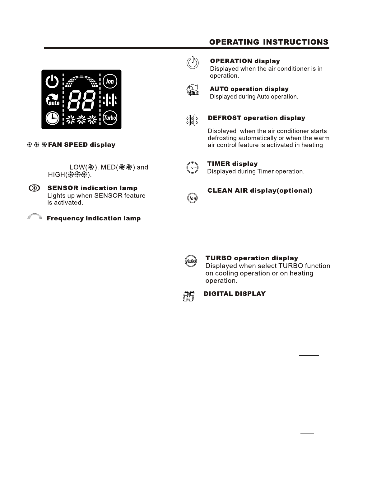
Display Window and Features:
(For heat pump models only):
mode.
Displays the selected fan
speed:
Displayed when TURBO function is selected
in cooling or in heating modes. This air con-
ditioner is equipped with an ionizer, which
This display is separated into ve zones.
Each zone illuminates based on the compressor’s frequency. For example, higher
frequency will illuminate more zones.
generates ions to remove microscopic particles from the air. Rooms become healthier
for those suffering from asthma or allergies
with the use of this feature.
Displays the current set temperature when
the air conditioner is in operation. When SELF
CLEAN feature is activated, its displays “SC”.
Remote Controller Features Ductless High Wall Mount. ONLY
The remote controller comes with a FOLLOW ME
feature which allows the remote controller to act as a
thermostat. This allows the unit to sense the temperature at the location of the remote controller, rather
than sensing the temperature at the indoor unit. The
indoor unit is installed high on a wall, thus the thermostat on the remote controller will provide a more
accurate temperature reading for the room. Consult
the remote controller manual for more information.
NOTE: The ceiling cassette does NOT come with this
feature.
4
Page 6
VMH Inverter-Flex Mini-Split OWNER’S MANUAL Heat Controller, Inc.
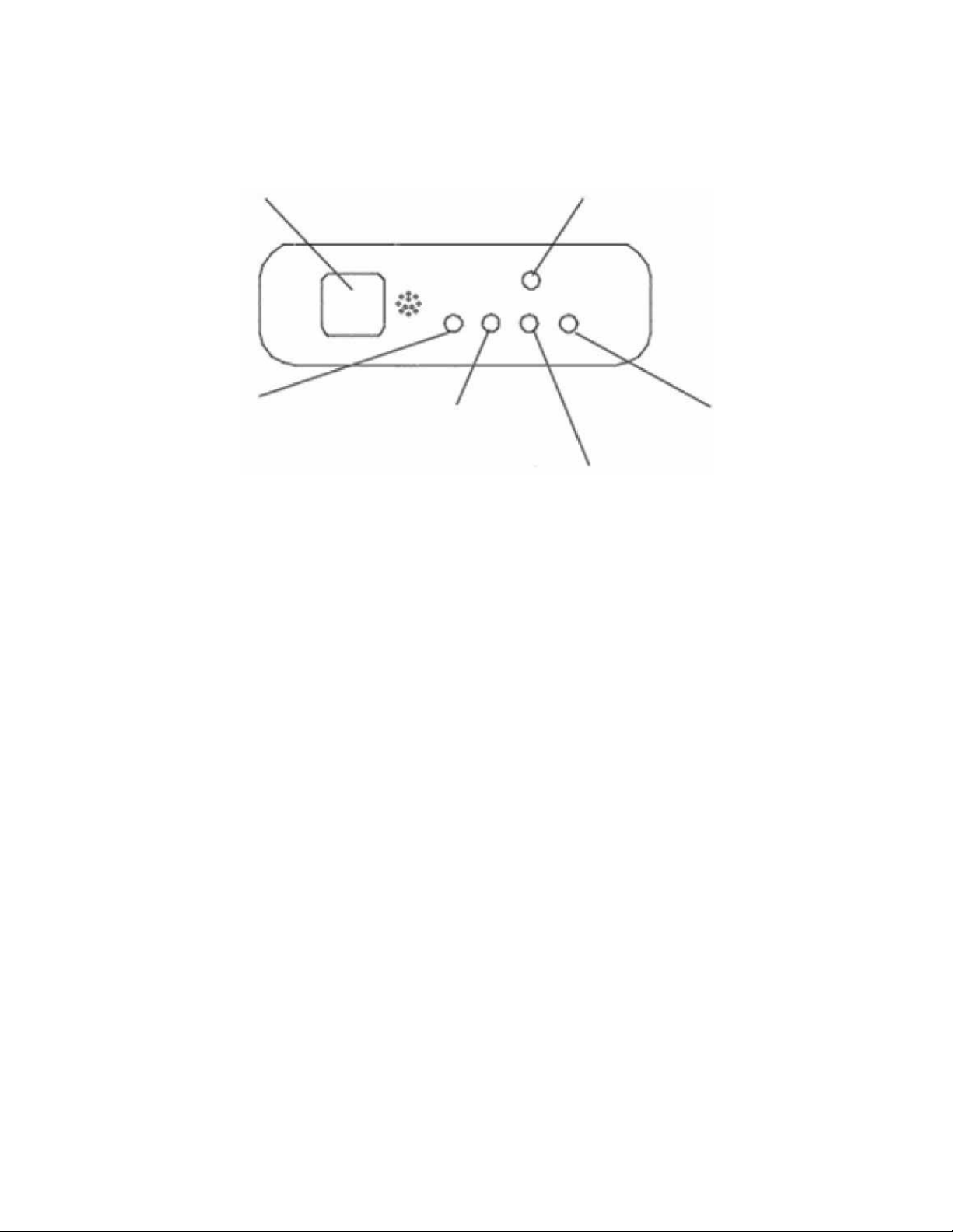
Manual buttonInfarred signal receiver
DISPLAY PANEL
mAlarm IndicatorkTime IndicatorjOperation Lamp
lDefrost/Fan Indicator
jOPERATION lamp
This indicator illuminates when the unit is operational.
kTIMER Indication lamp
Lights up during Timer operation.
lDEF./FAN Indication lamp
Lights up when the air conditioner starts defrosting automatically in heating operation or fan only mode is selected
mALARM Indication lamp
Flashes an error code sequence when malfunction occurs
n MANUAL button
This button is used to operate the unit temporarily in case you misplace the remote controller or its batteries are
exhausted. One press of the manual control button will lead to the forced AUTO operation. If press the button twice
within ve seconds, the unit will operate under forced COOL operation. The forced COOL operation is used for testing
purposes only, please do not choose it unless it is necessary.
.
5
Page 7

Heat Controller, Inc. OWNER’S MANUAL VMH Inverter-Flex Mini-Split
NOTE: This manual does not include Remote Controller Operations, see the <<Remote Controller Manual>>
packaged with the unit for details.
See chart below for operating conditions:
Mode Temp
Cooling
Heating
Dehumidication
Outdoor 5 to 122 -15 to 50
Indoor 62.6 17
Outdoor 5 to 93.2 -15 to 34
Indoor 86 30
Outdoor 32 to 122 0 to 50
Indoor >50 >10
Ambient Operating Conditions
Fahrenheit Celsius
Operating Conditions:
When cooling is needed year round, including when outdoor temperatures are apt to fall below freezing, our
V Series inverter driven ductless mini-split systems will continue to work, as they come with factory installed
low ambient controls. The low ambient feature works by regulating the head pressure by varying the amount of
air ow through the condenser, which helps to prevent evaporator freeze ups and low pressure problems due to
low ambient outdoor temperatures. Low ambient operation is a great feature for temperature/humidity sensitive
environments or applications such as server/computer rooms, supermarkets, restaurants, or cooling tower fans.
Additionally, a crank case heater is required and factory installed, as it is needed for use with the low ambient
controls. The crank case heater minimizes liquid refrigerant migration to the compressor when the compressor
is not operating and helps to keep the compressor oil warm enough so that it remains uid to prevent slugging.
Crank case heaters also assist to greatly reduce heat loss to ambient air. Together, the lower ambient feature
combined with the factory installed crank case heater, will not only allow the air conditioner to cool year round,
but will also prevent compressor failure in low ambient conditions.
Manual Operation:
Manual operation can be used temporarily to run the unit without using the remote controller. This feature can
also be used to test the unit during installation and troubleshooting by an authorized service technician.
Ductless Mini-split:
1 Open and lift the front panel up until it stops and
makes a clicking sound.
2 By pressing the manual control button, the unit will be
placed into forced AUTO operation mode.
3 Close the panel rmly to its original position.
Ceiling cassette’s manual button is located on the
Ceiling panel.
CAUTION
• Once you push the manual button, the operation mode will
change in the following order:
AUTO COOL OFF
• By pushing the button twice, the unit will be placed into
forced COOL mode, which can be used for testing purposes.
• By pushing the button a third time, the air conditioner will
stop operating and turn off.
• To restore use of the remote controller to control the unit,
simply begin to operate the unit with the remote controller.
6
Page 8

VMH Inverter-Flex Mini-Split OWNER’S MANUAL Heat Controller, Inc.
NOTE: The remote controller provided with your unit may
differ in appearance. Please refer to the <<Remote Controller
Manual>> supplied with the unit to operate the unit properly.
( C)
Ductless Mini-Split
• Adjust the air ow direction properly, otherwise it might cause
discomfort or cause uneven room temperatures.
• Adjust the horizontal louver using the remote controller.
• Adjust the vertical louver manually.
To set the vertical (up-down) air ow direction
Perform this function while the unit is in operation. Press the
SWING button on the remote controller to move the louver to the
desired direction. The angle of the horizontal louver moves 6° for
each press of the button.
To set the horizontal (left-right) air ow direction
Adjust the vertical louver manually using the lever on the left or right
side of the vertical louver arm (depending on model). Take care not
to catch ngers on the fan, horizontal louver or to damage vertical
louvers. Move the lever to the desired position to direct air ow.
To automatically swing the air ow direction
(up - down)
Perform this function while the air conditioner is in operation.
• Hold the SWING button without releasing it for more than
2 seconds. The horizontal louver will swing up and down
automatically.
• To stop the function, press the SWING button again.
CAUTION!
!
• The swing function will be disabled when air conditioner is not in operation
(including when the TIMER ON is set).
• Do not operate the air conditioner for long periods with air ow direction
set downward in cooling or dry mode. Otherwise, condensation may occur
on the surface of the horizontal louver causing moisture to drop on the
oor or on furnishings.
The swing function will be disabled when the air conditioner is not in
• Do not move the horizontal louver manually. Always use the SWING button.
operation (including when the TIMER ON is set).
• When the
horizontal louver might not move for approximately 10 seconds.
• Open angle of the horizontal louver should not be set too small, as
COOLING or HEATING performance may be impaired due to too
restricted air ow area. Do not operate unit with horizontal louver in closed
position.
button
• When the air conditioner is connected to power (initial power), the
horizontal louver may generate a sound for 10 seconds, this is a normal
operation.
air conditioner is started immediately after it was stopped, the
Ceiling Cassette
• Refer to the remote controller manual packaged with your unit.
• Use the air direction bottom to move the louvers to desired direction.
• Use swing button to activate automatic swing.
• In cooling mode, it’s best to keep the louvers horizontal to prevent
excess condensation.
• In heating mode, it’s best to point the louvers down, such that they
are open all the way.
7
Page 9

Heat Controller, Inc. OWNER’S MANUAL VMH Inverter-Flex Mini-Split
AUTO operation
• When you set the air conditioner to AUTO mode, it will automatically select
cooling, heating (heat pump models only), or fan only operation depending
on what temperature you have selected and the actual room temperature.
• The air conditioner will control room temperature automatically around
the temperature set point you select.
• If the AUTO mode is uncomfortable, you can change desired temperature settings manually.
ECONOMY/SLEEP operation
• When you push ECONOMY button on remote controller it activates
2°F
2°F
2°F
2°F
SLEEP mode. During cooling, heating (heat pump only), or AUTO operation, the air conditioner will automatically increase (cooling) or decrease (heating) 2°F (1°C) per hour.
• The set temperature will become steady 2 hours later.
• The SLEEP mode will turn off after 7 hours and revert back to the previ-
ous settings.
• The fan speed will be automatically controlled.
• This feature can maintain the most comfortable temperature and save
more energy during use.
DRY MODE/DEHUMIDIFYING operation:
• The temperature is regulated while dehumidifying by repeatedly turning
on and off of the cooling operation or fan only. The fan speed will be automatically controlled. In this mode, if the room temperature is lower than
50°F (10°C) the compressor will stop. The compressor will restart when
the room temperature is above 53.6°F (12°C).
Optimal Usage Tips:
To achieve optimal performance, please note the following:
• Adjust the air ow direction correctly so that it is not directed directly
blowing on people/animals.
• Adjust the temperature to achieve the highest comfort level. Do not ad-
just the unit to excessive temperature levels.
• When in COOL or HEAT modes close any open doors and windows within
the room that the unit is operating in to increase performance.
• Use TIMER ON button on the remote controller to select a time you want
to start your air conditioner.
• Do not put any objects near air inlet or air outlet, as the efciency of the
air conditioner may be reduced and the air conditioner may stop running
due to air ow blockages.
• Clean the air lter periodically, otherwise cooling or heating performance
may be reduced.
• Do not operate unit with louvers in a closed position
• SUGGESTION: For units with an electric heater, when the outside
ambient temperature is below 32°F (0°C), we strongly recommend that
you keep the unit powered on in order to guarantee it runs smoothly.
8
Page 10

VMH Inverter-Flex Mini-Split OWNER’S MANUAL Heat Controller, Inc.
MODE CONFLICTS:
While simultaneously operating more than one indoor unit, ensure that all operating modes
do not conict with one another. For example: one unit can not be in the heat mode, while
another is in cooling mode.
• The rst unit to initially start is considered the primary unit.
• Heat mode takes precedence. When the primary unit is placed in heat mode, all other units
in the system must also be ran in the heat mode.
• When the primary unit is on in the cool mode, the other units in the system can only be ran
in cool, fan, dehumidify, or fan only modes.
• Ductless mini-splits will display a “P5” error code during a mode conict.
• Ceiling cassettes will ash the operation light rapidly, while the Defrost and Alarm lights
remain solid. The Timer light will be off. When the lights react in this manner, it means the
indoor units have a mode conict.
9
Page 11

Heat Controller, Inc. OWNER’S MANUAL VMH Inverter-Flex Mini-Split
NOTE: Supply power must be disconnected before
cleaning the indoor unit.
Do not use an overly wet cloth to clean the unit as
it may damage the electronic components. A damp
cloth can be used if needed.
Never use water hotter than 104°F (40°C) to clean the
front panel. It could cause deformation or discoloration.
Hold the handle of the air lter and lift it up slightly
to take it out from the lter holder, then pull it
downwards.
Clean the lter with a vacuum cleaner or with
warm water. Be sure it is thoroughly dry before
replacing.
10
Page 12

VMH Inverter-Flex Mini-Split OWNER’S MANUAL Heat Controller, Inc.
4. Remove the Air Freshening Filter (optional lters:
plasma dust collector/silver ion lter/bio lter/vitamin
C lter) from it support frame.
The installation and removing method of the air freshening lter is different depending on the models. See the
pictures marked 1 and 2 on the left.
• Clean the air freshening lter at least once a month,
and replace it every 4-5 months.
• Clean it with a vacuum cleaner, then dry it in a cool
place.
5. Install the air freshening lter back into position.
6. Insert the upper portion of the air lter back into the unit
taking care that the left and right edges line up correctly
when placing lter into position.
Maintenance
If you do not plan on use the unit for a long period of time:
1. Clean the indoor unit and air lter.
2. Select FAN only mode, let the indoor fan run for a while
to dry the inside of the unit.
3. Disconnect the power supply and remove the batteries
from the remote controller.
4. Check components of the outdoor unit periodically.
Contact a local dealer or an authorized servicer if the unit
requires servicing.
NOTE: Before you clean the air conditioner, be sure to
switch the unit off and disconnect the power supply.
When the air conditioner is to be used again:
• Use a dry cloth to wipe off the dust accumulated on rear
air intake grille in order to avoid the dust blowing out from
the outdoor unit.
• Check that the wiring is not broken off or disconnected.
• Check that the air lter is installed.
• Check if the air outlet or inlet is blocked after the air condi-
tioner has not been used for a long time.
11
Page 13

Heat Controller, Inc. OWNER’S MANUAL VMH Inverter-Flex Mini-Split
CARE AND MAINTENANCE
CASSETTE TYPE
2. Take out the air-in grill (together with the air filter shown
o
in Fig. B). Pull the air-in grill down at 45 and lift it up
to take out the grill.
3. Dismantle the air filter
4. Clean the air filter(Vacuum cleaner or pure water may
be used to clean the air filter. If the dust accumulation
is too heavy , please use soft brush and mild detergent
to clean it and dry out in cool place) .
Fig. A
1. Open the air-in grill
Push the grill switches towards the middle simultaneously
as indicated in Fig. A. Then pull down the air-in grill.
Cautions: The control box cables ,which are originally
connected with the main body electrical terminators must be
pulled off before doing as indicated above.
DUCT AND CEILING TYPE
2. Take out the air-in grill.
3. Dismantle the air filter
4. Clean the air filter (Vacuum cleaner or pure water may
be used to clean the air filter. If the dust accumulation
is too heavy , please use soft brush and mild detergent
to clean it and dry out in cool place) .
1. Open the air-in grill
Push the grill switches towards the middle simultaneously
as indicated in follow figure sketch. Then pull down the
air-in grill.
Cautions: The control box cables ,which are originally
connected with the main body electrical terminators
must be pulled off before doing as indicated above.
The air-in side should face up when using vacuum
cleaner. (See Fig. C)
The air-in side should face down when using water.
(See Fig. D)
Cautions : Do not dry out the air filter under direct
sunshine or with fire.
5. Re-install the air filter
6. Install and close the air-in grill in the reverse order of
step 1 and 2 and connect the control box cables to the
corresponding terminators of the main body .
Note: High-static Pressure Parvis Split Type has no
CARE AND MAINTENANCE
Fig.B
Ceiling Cassette
1. Open the air-intake grille.
Push the grille switches towards the middle
simultaneously as indicated in Fig. A. Then pull down the
air-intake-grille.
2. Take out the air-intake grille (together with the air lter
shown in Fig. B). Pull the air-intake grille down at 45° and
lift it up to take it out of the grille.
3. Clean the air lter (Vacuum cleaner or pure water may
be used to clean the air lter. If the dust accumulation is
heavy, use a soft brush and mild detergent to clean it and
dry out in cool place before putting in back in operation.
Fig. C
Fig. D
12
Page 14

VMH Inverter-Flex Mini-Split OWNER’S MANUAL Heat Controller, Inc.
Typical Operational Occurrences
The following events may occur during normal operation.
1. Protection of the air conditioner.
Compressor protection
• If the unit is stopped and then immediately restarted again, the compressor will not operate for
about 3 minutes in order to protect the compressor.
Anti-cold air (heat pump models only)
• The unit is designed not to blow cold air in HEAT mode, when the indoor heat exchanger is in
one of the following three situations and the set temperature has not been reached.
A) When heating has just starting.
B) Defrosting is occurring
C) Low temperature heating is occurring
Defrosting (Cooling and heating models only)
• The indoor or outdoor fan stop running when defrosting (heat pump models only).
• Frost may accumulate on the outdoor unit during heat cycle when outdoor temperature is low
and humidity is high, resulting in lower heating efciency of the air conditioner.
• During this condition, air conditioner will stop the heating operation and start defrosting auto-
matically.
• Defrost time may vary from 4 to 10 minutes according to the outdoor temperature and the
amount of frost buildup on the outdoor unit.
2. Mist or steam are being emitted
• A white mist may emit from the indoor unit due to a large temperature difference between air
inlet and air outlet in COOL mode in an indoor environment that has a high relative humidity.
• A white mist may emit due to moisture generated from the defrosting process when the air conditioner restarts in HEAT mode operation after defrosting.
3. Typical sounds
• You may hear a low hissing sound when the compressor is running or has just stopped running.
This sound is the sound of the refrigerant owing or coming to a stop.
• You can also hear a low “squeak” sound when the compressor is running or has just stopped
running. This is caused by heat expansion and cold contraction of the plastic parts in the unit
when the temperature is changing.
• A noise may be heard due to louver restoring its original position when power is rst turned on.
• A sizzling sound may be heard occasionally when the unit is defrosting.
4. Dust is blown out from the indoor unit
• This is a normal condition when the air conditioner has not been used for a long time or during
rst use of the unit and an accumulation of dust has formed on the unit’s outlet. Cleaning dust
off of the unit before operation will prevent this.
5. A peculiar smell comes out from the indoor unit
• This is caused by the indoor unit giving off smells permeated from building material, from furni-
ture, or smoke. A burning smell could mean there is something wrong with the unit. Power off
the unit and call an authorized servicer.
6. Operating mode changes to FAN ONLY mode
• When the indoor temperature reaches the temperature set point on air conditioner, the com-
pressor will stop automatically, and the air conditioner mode changes to FAN only mode. The
compressor will start again when the indoor temperature rises above the set point in the COOL
mode or falls below the set point in the HEAT mode (heat pump only models).
13
Page 15

Heat Controller, Inc. OWNER’S MANUAL VMH Inverter-Flex Mini-Split
7. Condensation
• Dripping water may generate on the surface of the indoor unit when cooling in relatively high
humidity. Adjust the vertical louver to the maximum air outlet position and select HIGH fan
speed. NOTE: Water could drop onto the oor or objects below the indoor unit.
8. Heating mode (heat pump models only)
• The air conditioner draws in heat from the outdoor unit and releases it via the indoor unit dur-
ing heating operation. When the outdoor temperature falls, heat drawn in by the air conditioner decreases accordingly. At the same time, the heat load of the air conditioner increases
due to larger difference between indoor and outdoor temperature. If a comfortable temperature can’t be achieved by the air conditioner, we suggest you use a supplementary heating
device.
9. Auto-restart function
• Power failure during operation will stop the unit completely.
• For units with the Auto-restart feature, when the power restores, the unit restarts automati-
cally using the previous settings preserved by the memory function of the unit. Timer settings
may need to be adjusted after a power failure.
10. Electrical interference
• Electronic equipment which uses wireless radio transmitters within 3 ft (1m) of the air conditioning unit may cause the unit to malfunction. Disconnect the unit with power and then
re-connect the unit with power again. Push the ON/OFF button on the remote controller to
restart operation. Ensure that the air conditioner unit is as far away from any electronic interference sources as possible, otherwise wireless interference can occur.
14
Page 16

Troubleshooting Tips
Stop the air conditioner immediately if one of the following errors occurs. Disconnect the power and contact
an authorized servicer.
If any of the following error codes appear on the LED window or display, disconnect the power
and contact an authorized servicer
Call for
service if
Symptoms Possible Cause/Things to Check What should be done?
Unit does
no start or
operate at
all
Poor cooling
or heating
(heat pump
models only)
performance
Fuse blows or circuit breaker trips frequently
Other abnormal situations (such as burning smells) that can’t be resolved using the steps outlined
below.
Is there power supplied to the unit?
Fuse may have blown out or a circuit
breaker has been tripped.
Batteries in remote controller may be dead
or installed incorrectly.
Is the unit’s timer set? Wait or cancel timer setting.
Inappropriate temperature setting. Set temperature correctly.
Air lter may be blocked Clean the air lter to prevent air ow blockages.
Doors or windows are open.
Air inlet or outlet of indoor or outdoor unit
are blocked.
Wait for the power to be restored or call an
electrician to address any power supply problem.
Replace the fuse or ip the circuit breaker.
Replace the batteries and ensure the polarities
are correct.
Close the doors or windows within the area
being cooled/heated to increase efciency and
performance.
Clear obstructions away, then restart the unit.
Compressor time delay has been activated
If the problem persists after performing these checks, or if you notice burning smells, or the operation
indicator light ashes repeatedly, immediately stop operation, disconnect the power, and call an authorized
service center.
Wait approximately 3 minutes for the compressor
to turn on and the unit to begin cooling/heating.
15
Page 17

9/2012
Design, specifications, performance data and materials subject to change without notice.
1900 Wellworth Ave., Jackson, Michigan 49203 • Ph. 517-787-2100 • Fax 517-787-9341
www.heatcontroller.com
THE QUALITY LEADER IN CONDITIONING AIR
 Loading...